
EPsolar EPIPDB-COM 20A + MT-1
PWM Solar Charge Controller 20A Dual Battery with Remote Meter MT-1
Model: EPIPDB-COM 20A + MT-1 | Brand: EPsolar
1. Introduction
This instruction manual provides detailed information for the installation, operation, and maintenance of your EPsolar EPIPDB-COM 20A Dual Battery Solar Charge Controller and the accompanying MT-1 Remote Meter. This system is designed to efficiently manage power from your solar panels to charge two independent battery banks, making it ideal for RVs, caravans, and boats.
The EPIPDB-COM controller utilizes advanced Pulse Width Modulation (PWM) charging technology to optimize battery charging, extend battery lifespan, and protect against over-discharging and over-charging. The MT-1 remote meter offers convenient monitoring and control of your solar system's performance.
Package Contents:
- 1 x 20A Dual Battery Solar Charge Controller (EPIPDB-COM 20A)
- 1 x MT-1 Remote Meter
- 1 x RJ45 Communication Cable (approx. 10 meters)
- User Manuals (for controller and MT-1)

Figure 1: EPsolar EPIPDB-COM 20A Dual Battery Solar Charge Controller, MT-1 Remote Meter, and communication cable.
2. Product Components and Overview
The system consists of the main solar charge controller unit and the remote meter. Understanding the components and their connections is crucial for proper setup and operation.
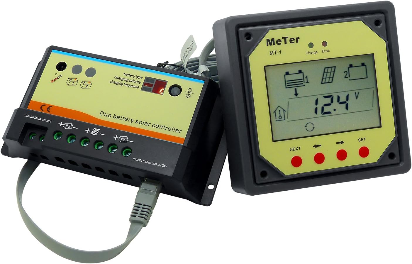
Figure 2: The EPIPDB-COM 20A controller connected to the MT-1 remote meter via the communication cable.
2.1 Solar Charge Controller (EPIPDB-COM 20A)
This is the core unit responsible for managing the solar charging process for two battery banks. It features multiple terminals for connections and indicators for status.

Figure 3: Labeled diagram of the EPIPDB-COM 20A controller's terminals and indicators.
Key Components (Refer to Figure 3):
- Local Temp. Sensor: For internal temperature compensation.
- Remote Temp. Sensor Connection: Terminal for connecting an optional external remote temperature sensor.
- Battery 1 Terminals (+/-): For connecting the first battery bank.
- Battery 2 Terminals (+/-): For connecting the second battery bank.
- PV Input Terminals (+/-): For connecting the solar panel array.
- Remote Meter Connection: RJ45 port for connecting the MT-1 remote meter.
- Indicators: LEDs for battery type, charging priority, and charging frequency.
- Setting Button: For adjusting controller parameters.
2.2 Remote Meter (MT-1)
The MT-1 is an external LCD display unit that provides real-time monitoring of your solar system's status and parameters. It connects to the main controller via an RJ45 cable.

Figure 4: The MT-1 Remote Meter and its communication cable.
MT-1 Display and Buttons (Refer to Figure 5):

Figure 5: Labeled diagram of the MT-1 Remote Meter's LCD display and buttons.
- LCD Screen: Displays various system parameters.
- Battery Icon: Indicates battery status.
- Solar Icon: Indicates solar input status.
- Remote Temp. Icon: Indicates remote temperature sensor status.
- Local Temp. Sensor Icon: Indicates internal temperature sensor status.
- Setting Icon: Appears when in setting mode.
- Error Indicator: Lights up if an error occurs.
- Circle Indicator: General status indicator.
- Backlight Icon: Indicates backlight status.
- Self-test Indicator: Appears during self-test.
- Unit Indicator: Displays units (e.g., V, A, Wh).
- Extremum Indicator: Shows min/max values.
- NEXT Button: Navigates through display screens or options.
- SET Button: Confirms selections or enters setting mode.
3. Setup and Installation
Proper installation is critical for the safe and efficient operation of your solar charge controller. Please follow these steps carefully.
3.1 Mounting the Controller
- Choose a dry, well-ventilated location away from direct sunlight and heat sources.
- Ensure there is sufficient space around the controller for air circulation.
- Mount the controller vertically on a non-flammable surface using appropriate screws.

Figure 6: Dimensions of the EPIPDB-COM 20A controller for mounting reference.
3.2 Wiring Connections
Important: Always connect the batteries first, then the solar panels. Disconnect in the reverse order (solar panels first, then batteries).
- Connect Battery 1: Connect the positive (+) and negative (-) terminals of your first battery bank to the "Battery 1" terminals on the controller. Ensure correct polarity.
- Connect Battery 2: Connect the positive (+) and negative (-) terminals of your second battery bank to the "Battery 2" terminals on the controller. Ensure correct polarity.
- Connect Solar Panels: Connect the positive (+) and negative (-) terminals of your solar panel array to the "PV Input" terminals on the controller. Ensure correct polarity.
- Connect Remote Temperature Sensor (Optional): If using an external remote temperature sensor, connect it to the designated "Remote Temp. Sensor" terminal. This improves charging accuracy by compensating for battery temperature.
- Connect MT-1 Remote Meter: Plug one end of the RJ45 communication cable into the "Remote Meter Connection" port on the controller and the other end into the MT-1 remote meter.
Note on Negative Grounding: This controller is a negative-grounded device. Ensure all negative connections are properly grounded if required by your system design.
4. Operating Instructions
4.1 Solar Charge Controller Operation
Once connected, the controller will automatically detect the system voltage (12V or 24V). You may need to configure battery type and charging priority.
4.1.1 Setting Battery Type
The controller supports Sealed, Gel, and Flooded battery types. To set the battery type:
- Press the "Setting" button on the controller.
- The "battery type" LED will flash.
- Press the "Setting" button repeatedly to cycle through the options:
- 0: Sealed battery (pre-set)
- 1: Gel battery
- 2: Flooded battery
- The selected battery type will be saved automatically after 5 seconds of inactivity.
4.1.2 Setting Charging Priority
This controller allows you to set the charging priority between Battery 1 and Battery 2. The controller will automatically calculate the rest for Battery 2 based on Battery 1's setting.
- Press the "Setting" button until the "charging priority" LED flashes.
- Press the "Setting" button repeatedly to cycle through the charging ratio options for Battery 1.
- The selected priority will be saved automatically after 5 seconds of inactivity.
| Number Shows | Battery #1 Charging | Battery #2 Charging |
|---|---|---|
| 0 | 0% | 100% |
| 1 | 10% | 90% |
| 2 | 20% | 80% |
| 3 | 30% | 70% |
| 4 | 40% | 60% |
| 5 | 50% | 50% |
| 6 | 60% | 40% |
| 7 | 70% | 30% |
| 8 | 80% | 20% |
| 9 | 90% (pre-set) | 10% |
Note: In the normal charging status, the controller will divide the charging as per the setting. If only one battery is connected, the controller will charge that battery fully regardless of the priority setting.
4.1.3 Charging Frequency Setting
The 3rd LED on the controller indicates the PWM charging frequency. To change this setting:
- Press the "Setting" button until the "charging frequency" LED flashes.
- Press the "Setting" button repeatedly to cycle through the options:
- 0: 25Hz (pre-set)
- 1: 50Hz
- 2: 100Hz
- The selected frequency will be saved automatically after 5 seconds of inactivity.
4.2 Remote Meter MT-1 Operation
The MT-1 meter provides a user-friendly interface to monitor your system. Use the "NEXT" and "SET" buttons to navigate and configure settings.
4.2.1 Displaying Parameters
Press the "NEXT" button to cycle through various display screens, which may include:
- Battery Voltage (V)
- Solar Panel Voltage (V)
- Charging Current (A)
- Amp-hour (Ah) charged
- Watt-hour (Wh) charged
- Battery Temperature (if remote sensor connected)
- Min/Max Voltage records
4.2.2 Setting Parameters via MT-1
The MT-1 allows for setting battery type and temperature compensation coefficient. Refer to the specific MT-1 manual for detailed steps on these advanced settings.
- Battery Type Selectable: Similar to the controller's setting, but done via the MT-1 interface.
- Battery Ah Setting Function: Allows input of battery capacity for more accurate Ah/Wh tracking.
- Temperature Compensation Coefficient Adjustable: Fine-tune temperature compensation for charging.
Important Note: Both batteries must be connected to the charge controller for the MT-1 to function correctly. Otherwise, a default error may occur.
5. Maintenance
Regular maintenance ensures the longevity and optimal performance of your solar charge controller system.
- Check Connections: Periodically inspect all wiring connections for tightness and corrosion. Loose connections can cause voltage drops and overheating.
- Clean Terminals: If corrosion is present, disconnect power and clean terminals with a wire brush.
- Inspect Wiring: Check for any signs of wear, fraying, or damage to the insulation of all cables. Replace damaged wiring immediately.
- Environmental Check: Ensure the controller's mounting area remains dry, clean, and well-ventilated. Remove any dust or debris that may accumulate on the controller's heatsink.
- Battery Health: Monitor your batteries regularly. Ensure they are properly maintained according to the battery manufacturer's guidelines.
6. Troubleshooting
This section provides solutions to common issues you might encounter with your solar charge controller.
| Symptom | Possible Cause / Solution |
|---|---|
| LED blinking, short circuit | Check the PV and battery connections. Ensure they are correct and secure. |
| LED slowly flashing, fully charged | This indicates the battery is fully charged and the controller is in float charge mode. This is normal operation. |
| LED ON, on charging | This indicates the battery is currently being charged. This is normal operation. |
| LED frequent flashing, with battery, no charging | Check solar panel input. Ensure sufficient sunlight and proper PV connection. Check for open circuit in PV array. |
| LED OFF, no battery or over voltage | Ensure batteries are connected and have sufficient voltage. Check for over-voltage condition from PV array (though controller has protection). |
| MT-1 displays error or no data | Ensure both batteries are connected to the charge controller. Check the RJ45 communication cable connection between the controller and MT-1. |
If the issue persists after following these steps, please contact customer support.
7. Specifications
7.1 EPIPDB-COM 20A Solar Charge Controller
| Parameter | Value |
|---|---|
| Nominal System Voltage | 12V/24V Auto recognition |
| Rated Charge Current | 20A |
| Rated Discharge Current | 20A |
| Maximum Battery Voltage | 30V |
| Max. Solar Input Voltage | 30V (12V system), 55V (24V system) |
| Max. PV Input Power | 240W (12V system), 480W (24V system) |
| Grounding | Negative Grounded |
| Battery Type Options | Sealed, Gel, Flooded |
| Self-consumption | 4mA at night, 10mA at charging |
| Temperature Compensation | -30mV/°C/12V |
| Terminals | 4mm² |
| Operating Temperature | -35°C to +55°C |
| Dimensions (L x W x H) | Approx. 153mm x 76mm x 37mm (6.02 x 2.99 x 1.46 inches) |
7.2 MT-1 Remote Meter
| Parameter | Value |
|---|---|
| Rated Voltage | 12V |
| Min Voltage (suggest) | 8.0V |
| Strong Backlight On Current | <23mA |
| Low Backlight On Current | <20mA |
| Backlight and LED Indicator Off Current | <17mA |
| Operating Temperature | -40°C ~ +60°C |
| LCD Operation Temperature | -10°C ~ +40°C |
| Humidity | ≤95% N.C. |
| Communication Cable | RJ45 (8PIN), 10 meter |
8. Warranty and Support
Information regarding the product warranty and customer support details was not available in the provided product data. Please refer to the product packaging or the manufacturer's official website for warranty terms and contact information for technical support.
Related documentsEPIPDB-COM 20A + MT-1


Ask a question about this manual
Ask about setup, troubleshooting, compatibility, parts, safety, or missing instructions. Manuals+ will review the question and use this page’s manual context to help answer it.