
1. Product Overview
The Aitoserlea Adjustable Constant Current Electronic Load is a versatile power tester designed for discharging and testing various power sources. It features intelligent discharge resistance and provides precise measurements for voltage, current, power, capacity, and impedance. This device is suitable for testing batteries, power supplies, and other electrical components within its specified operating limits.
Key Features:
- Voltage measurement range: 0.00V ~ 200V, resolution accuracy: 0.01V
- Current measurement range: 0.00A ~ 20A, resolution accuracy: 0.01A
- Power measurement range: 0000.00 ~ 150W, resolution accuracy: 0.01W
- Impedance measurement range: 1 ~ 999.9 Ohm, resolution accuracy: 0.01 Ohm
- Temperature measurement range: 0 ~ 99 ℃, resolution accuracy: 1 ℃
- Capacity accumulation range: 0 ~ 999.999Ah, resolution accuracy: 0.01Ah
- Timing maximum time: 999 hours 59 minutes 59 seconds
- Overvoltage and overcurrent alarm settings.

Figure 1: Aitoserlea Electronic Load Tester with key dimensions (156mm x 96mm x 58mm). This image shows the overall physical layout of the device, including the cooling fan, heat sink, display, and connection terminals.
2. Setup Instructions
- Unpacking: Carefully remove the electronic load tester from its packaging. Inspect for any visible damage.
- Power Connection: The device requires a 4V to 30V DC power supply for its internal operation. Connect a suitable power adapter to the designated power input port.
- Connecting the Load:
- Identify the input/output interface, which consists of 100A high current bite screw studs.
- Connect the power source or battery you wish to test to these terminals. Ensure correct polarity (positive to positive, negative to negative).
- Various connection options are available, including screw terminals, USB A, micro USB, mini USB, USB C, and barrel jack, depending on the specific model and accessories.

Figure 2: Example of the electronic load tester connected to a 12V battery using alligator clips on the screw terminals. This demonstrates a typical setup for discharging or testing a battery.
- Initial Power On: Once connected, the LCD display should illuminate, showing initial readings.
- USB Functionality: The USB port on this load meter is primarily for connecting trigger equipment. Note: Current adjustment is performed using the physical knobs on the device, not via USB.
3. Operating Instructions
This section details how to operate your electronic load tester for various testing scenarios.
3.1. Display Overview

Figure 3: Close-up view of the LCD display, showing real-time voltage (V), current (A), temperature (℃), accumulated capacity (Ah), accumulated power (Wh), and elapsed time (T).
The Micropower LCD Module displays real-time measurements including voltage, current, power, accumulated capacity, accumulated power, impedance, and temperature. It also shows the elapsed timing.
3.2. Adjusting Load Current
The load current is adjusted using the two physical knobs on the device:
- Coarse Adjustment Knob: For large changes in current.
- Fine Adjustment Knob: For precise, small adjustments to the current.
Turn the knobs clockwise to increase the load current and counter-clockwise to decrease it. Observe the current reading on the LCD display as you adjust.
3.3. Setting Alarm Parameters
The device allows setting alarm thresholds for overvoltage, low voltage, and overcurrent. When a set threshold is exceeded, the device will display an alert interface to notify the user.
- Overvoltage Reminder: Setting range 1V ~ 200V.
- Low Voltage Reminder: Setting range 0V ~ 190V.
- Overflow (Overcurrent) Reminder: Setting range 0.2A ~ 100A.
Refer to the device's button interface for specific instructions on how to enter the settings menu and adjust these parameters. Typically, this involves a combination of presses on the single control button.
3.4. Timing Measurement and Reminders
The device can time discharge processes up to 999 hours, 59 minutes, and 59 seconds. It also features timing measurement reminder settings:
- Countdown: Can be set for up to 24 hours.
- Small Current Standby Reminder: If current is less than 2W / 0.5 hours, it reminds. Timing begins when current exceeds 0.5W.
3.5. Testing USB Power Sources
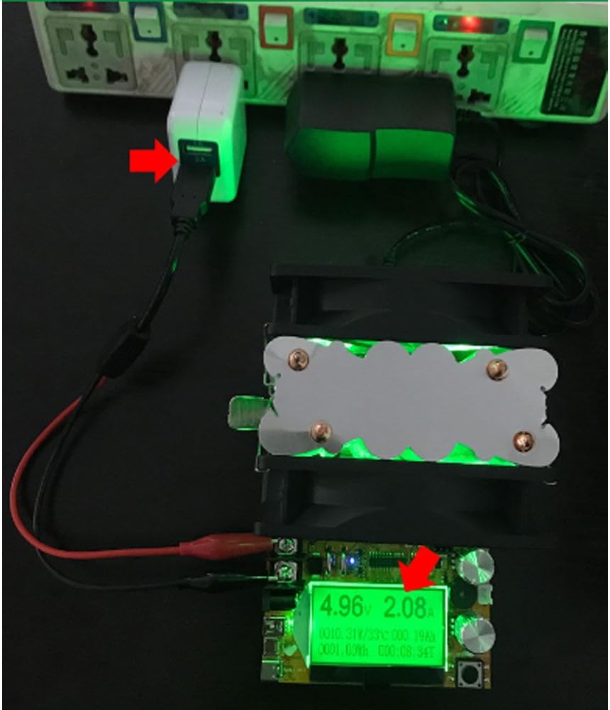
Figure 4: The electronic load tester connected to a USB power adapter, demonstrating its capability to test USB power sources. The display shows the voltage and current being drawn.
The device can be used to test the output of USB power adapters and power banks. Connect the USB output of the power source to the corresponding USB input on the electronic load tester. Adjust the load current using the knobs to draw a desired current and observe the voltage stability and current delivery capabilities of the USB source.
4. Maintenance
- Cleaning: Use a soft, dry cloth to clean the exterior of the device. Do not use abrasive cleaners or solvents. Ensure no liquids enter the device.
- Storage: Store the electronic load tester in a cool, dry place away from direct sunlight and extreme temperatures.
- Ventilation: Ensure the cooling fan and heat sink are free from dust and obstructions to maintain optimal performance and prevent overheating. Periodically check and clean the fan blades if necessary.
- Handling: Handle the device with care to avoid physical damage to the circuit board or components.
5. Troubleshooting
- Device does not power on:
- Check if the power supply connected to the device is within the 4V to 30V DC range.
- Ensure the power supply is properly connected and functioning.
- Verify all connections are secure.
- No current draw or incorrect readings:
- Ensure the load (battery/power supply) is correctly connected to the input/output terminals with correct polarity.
- Check if the coarse and fine adjustment knobs are being turned.
- Verify the load source is providing power.
- Ensure the device is not in an alarm state (e.g., low voltage reminder preventing operation).
- Overheat warning:
- Ensure the cooling fan is operating and not obstructed.
- Check if the ambient temperature is within the operating range (-10 ℃ to +60 ℃).
- Reduce the load current to decrease power dissipation.
- USB current adjustment not working:
- The USB function is for connecting trigger equipment only. Current adjustment is exclusively done via the physical knobs on the load meter. This is not a malfunction.
6. Technical Specifications
| Parameter | Value |
|---|---|
| Input/Output Interface | 100A High Current Bite Screw Stud |
| Voltage Measurement Range | 0.00V ~ 200V (Resolution: 0.01V) |
| Current Measurement Range | 0.00A ~ 20A (Resolution: 0.01A) |
| Power Measurement Range | 0000.00 ~ 150W (Resolution: 0.01W) |
| Capacity Accumulation Range | 0 ~ 999.999Ah (Resolution: 0.01Ah) |
| Energy Accumulation Range | 0 ~ 9999.9Wh (Resolution: 0.01Wh) |
| Impedance Measurement Range | 1 ~ 999.9 Ohm (Resolution: 0.01 Ohm) |
| Temperature Measurement Range | 0 ~ 99 ℃ (Resolution: 1 ℃) |
| Timing Maximum Time | 999 hours 59 minutes 59 seconds |
| Power Supply for Measurement System | 4 ~ 30V DC |
| Refresh Time | > 500ms / time |
| Measurement Rate | Approx. 0.5 times / sec |
| Overvoltage Reminder Setting Range | 1 ~ 200V |
| Low Voltage Reminder Setting Range | 0 ~ 190V |
| Overflow Reminder Setting Range | 0.2 ~ 100A |
| Display Type | Micropower LCD Module LCM (Black Font Green Backlit, Chinese & English) |
| Product Size | 156mm * 96mm * 58mm |
| Operating Temperature | -10 ~ +60 ℃ |
| Working Humidity | 10 ~ 80% (non-condensing) |
| Working Pressure | 80 ~ 106kPa |
7. Warranty and Support
This product is manufactured by top-tool under the Aitoserlea brand.
For technical support, warranty inquiries, or service, please contact your retailer or the manufacturer directly. Please have your product model number (B076RDSMD3) and purchase information ready when contacting support.
While specific warranty details are not provided in this manual, standard consumer protection laws typically apply. Keep your proof of purchase for any warranty claims.