1. Introduction
The EPEVER VS2024AU is a Pulse Width Modulation (PWM) solar charge controller designed for efficient battery charging in various solar power systems. It features an integrated LCD display for dynamic monitoring of operating data and working conditions. This controller supports 12V/24V auto-work voltage and includes dual USB ports for charging electronic devices. Its advanced digital techniques and multiple load control modes make it suitable for solar home systems, traffic signals, solar street lights, and solar garden lamps.

Figure 1: Front view of the EPEVER VS2024AU Solar Charge Controller.
2. Key Features
- 3-Stage Intelligent PWM Charging: Bulk, Boost/Equalize, Float.
- Supports 3 battery charging options: Sealed, Gel, and Flooded.
- LCD display for dynamic device operating data and working condition display.
- Dual USB ports (5VDC/2.4A total) for electronic equipment charging.
- User-friendly button settings for comfortable and convenient operation.
- Multiple load control modes.
- Energy statistics function.
- Battery temperature compensation function.
- Extensive Electronic Protections: PV reverse polarity, Battery over voltage, Battery over discharge, Battery reverse polarity, Battery overheating, Load overload, Load short circuit, Controller overheating.
3. Safety Instructions
Please read all instructions and warnings in this manual before installation and operation. Keep this manual for future reference. Always ensure proper polarity and secure connections to prevent damage to the controller, battery, or other components. Disconnect all power sources before performing any wiring or maintenance. This device is intended for indoor use in a dry, well-ventilated environment. Avoid exposure to water, high humidity, or corrosive substances.
4. Product Overview
4.1 Components and Interfaces
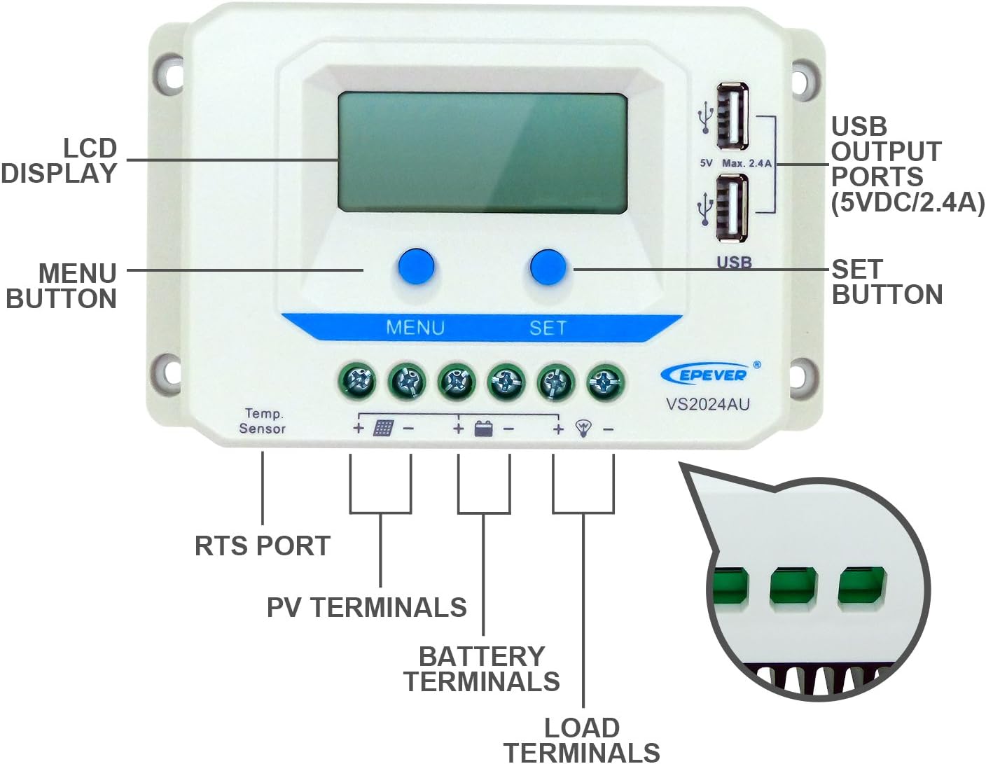
Figure 2: Labeled components of the VS2024AU controller. This includes the LCD display, Menu and Set buttons, USB output ports, RTS port, PV terminals, Battery terminals, and Load terminals.
4.2 Dimensions and Applications

Figure 3: The controller measures 16cm in length, 9.49cm in width, and 4.93cm in height. It features multiple load control modes, high reliability components, an informative black light LCD display, 12V/24V auto-work, and 5V dual USB 2.4A (Total) output.

Figure 4: The VS2024AU is suitable for various applications including home emergency equipment power supply, street lights, real-time battery monitoring, green energy solutions, and small power stations. It also features dual USB ports for charging mobile devices.
5. Setup and Installation
Proper installation is crucial for the safe and efficient operation of your EPEVER VS2024AU solar charge controller. Always connect the battery first. Please read the complete installation instructions to familiarize yourself with the installation steps before proceeding.
5.1 Wiring Diagram

Figure 5: Connection diagram showing the solar panel (3), controller, battery (1), and load (2). Ensure correct polarity for all connections. An inverter can also be connected to the battery.
5.2 Connection Steps
- Connect the Battery: Connect the battery to the controller's battery terminals. Ensure correct polarity (positive to positive, negative to negative). The controller will power on once the battery is connected.
- Connect the Solar Panel: Connect the solar panel to the controller's PV terminals. Ensure correct polarity.
- Connect the Load: Connect the load to the controller's load terminals. Ensure correct polarity.
Important: Always connect the battery first and disconnect the solar panels first when disassembling the system.
5.3 Installation Video Guide
Video 1: This video provides a visual guide to the unboxing, interface, installation, and basic settings of the EPEVER PWM Solar Charge Controller VS-AU Series, which includes the VS2024AU model. It demonstrates the physical connections and initial setup procedures.
6. Operating Instructions
6.1 LCD Display and Button Functions

Figure 6: The LCD displays various status icons and parameters. Icons include PV array status (Day, Night, No charging, Charging), Battery status (Battery capacity, In Charging, Battery voltage, current, temperature, Battery type), and Load status (Load ON, Load OFF, Load Voltage, Current, Load mode).
The controller features MENU and SET buttons for navigation and parameter adjustment. Pressing the MENU button cycles through different display interfaces. Holding the SET button allows entry into setting modes for parameters like battery type and load working mode.
6.2 Load Control Modes
The VS2024AU offers multiple load control modes to suit various application needs. These modes can be configured via the controller's interface:
- Manual Control Mode (Default): The load can be manually turned ON/OFF by pressing the load button.
- Light Control Mode: The load automatically turns ON at dusk and OFF at dawn.
- Dual Time Mode: Combines light control with a timer, allowing the load to operate for a set duration after dusk.
- Test Mode: For testing purposes.
Refer to the detailed instructions in the full product manual for specific parameter settings for each load control mode.
6.3 Battery Type Setting
The controller supports Sealed, Gel, and Flooded battery types. To set the battery type:
- Press the SET button to enter the setting interface.
- Press and hold the BATT button for 5 seconds to enter the battery type interface.
- Use the PV+/LOAD- buttons to select the desired battery type.
- Press the SET button to confirm the battery type.
7. Maintenance
To ensure optimal performance and longevity of your EPEVER VS2024AU solar charge controller, regular maintenance is recommended:
- Check Connections: Periodically inspect all wiring connections for tightness and corrosion. Loose connections can cause overheating and damage.
- Clean the Controller: Keep the controller clean and free from dust and debris. Use a dry cloth to wipe the exterior. Ensure the heat sink (Figure 7) is not obstructed for proper cooling.
- Inspect Wiring: Check all cables for signs of wear, fraying, or damage. Replace any damaged cables immediately.
- Monitor Performance: Regularly check the LCD display for normal operation and parameter readings. Note any unusual behavior or error codes.

Figure 7: Back view of the controller, highlighting the heat sink for thermal management.
8. Troubleshooting
If you encounter issues with your VS2024AU controller, refer to the following general troubleshooting steps. For detailed error codes and solutions, consult the comprehensive manual included with your product.
- No Display/No Power: Check battery connections and ensure the battery has sufficient charge. Verify all wiring is secure and correctly polarized.
- Battery Not Charging: Check solar panel connections and ensure the panel is receiving adequate sunlight. Verify solar panel voltage and current. Confirm the correct battery type is selected in the settings.
- Load Not Working: Check load connections and ensure the load is not overloaded or short-circuited. Verify the load control mode settings.
- Overheating: Ensure the controller is installed in a well-ventilated area and the heat sink is free from obstructions. Reduce the load if consistently overheating.
If problems persist after following these steps, contact EPEVER customer support or a qualified technician.
9. Specifications
Below are the technical specifications for the EPEVER VS2024AU 20A PWM Solar Charge Controller:
| Parameter | Value (VS2024AU) |
|---|---|
| Nominal System Voltage | 12V/24V Auto Work |
| Battery Input Voltage Range | 9V~32V |
| Rated Charge/Discharge Current | 20A |
| Max. PV Open Circuit Voltage | 50V |
| Battery Type Support | Sealed (Default), Gel, Flooded |
| Equalize Charging Voltage | Sealed:14.6V / Gel:No / Flooded:14.8V |
| Boost Charging Voltage | Sealed:14.4V / Gel:14.2V / Flooded:14.6V |
| Float Charging Voltage | Sealed/Gel/Flooded:13.8V |
| Low Voltage Reconnect Voltage | Sealed/Gel/Flooded:12.6V |
| Low Voltage Disconnect Voltage | Sealed/Gel/Flooded:11.1V |
| Self-consumption | ≤10mA/12V; ≤18mA/24V |
| Temperature Compensation Coefficient | -3mV/°C/2V (25°C) |
| Grounding | Common positive |
| USB Output | 5VDC/2.4A |
| Overall Dimension | 160.9x94.9x49.3 mm (6.3 x 3.74 x 1.94 inches) |
| Terminals | 10mm²/8AWG |
| Net Weight | 0.35kg (12.3 ounces) |
| Enclosure | IP30 |
| Working Environment Temperature | -25°C ~ +55°C |
| Humidity Range | ≤95% (N.C.) |
Note: The parameters above are for a 12V system. For a 24V system, multiply voltage parameters by two.

Figure 8: Detailed technical specifications for the EPEVER VS-AU series, including VS1024AU, VS2024AU, VS3024AU, VS4524AU, and VS6024AU models.
10. Warranty and Support
For warranty information, technical support, or service inquiries, please refer to the official EPEVER website or contact your authorized dealer. Keep your purchase receipt as proof of purchase for warranty claims.


