
1. Product Overview
The ELEGOO 8-Channel 5V DC Relay Module is designed for controlling various electrical loads using a microcontroller. It features 8 independent relays, each with normally open (NO) and normally closed (NC) contacts, and is optically isolated for enhanced safety and interference protection. This module is compatible with a wide range of microcontrollers including 8051, AVR, PIC, DSP, ARM, and MSP430.

Figure 1: ELEGOO 8-Channel Relay Module product packaging.
Key Features:
- 8-channel 5V DC relay interface board.
- Each channel requires approximately 70mA drive current.
- Equipped with high-current relays: 230V AC 10A, 30V DC 10A.
- Normally open and normally closed contacts available for each relay.
- Jumper selectable for TTL high or low level trigger.
- Power indicator and individual status indicators for each channel.
- Integrated freewheeling diode to protect the coil.
- Standard interface for direct control by microcontrollers.
- Optically isolated channels for safety and anti-interference.
2. Setup and Connections
This section details the physical connections required to integrate your ELEGOO 8-Channel Relay Module into your project.
2.1 Module Components
The module consists of:
- Relays: Eight individual 5V relays.
- Input Pins: VCC, GND, IN1-IN8.
- Output Terminals: Normally Open (NO), Common (COM), Normally Closed (NC) for each relay.
- Power Indicator LED: Illuminates when the module is powered.
- Status Indicator LEDs: One for each relay, indicating its activation status.
- Jumper (JD-VCC): Used to select the power source for the relay coils (isolated or shared with logic).
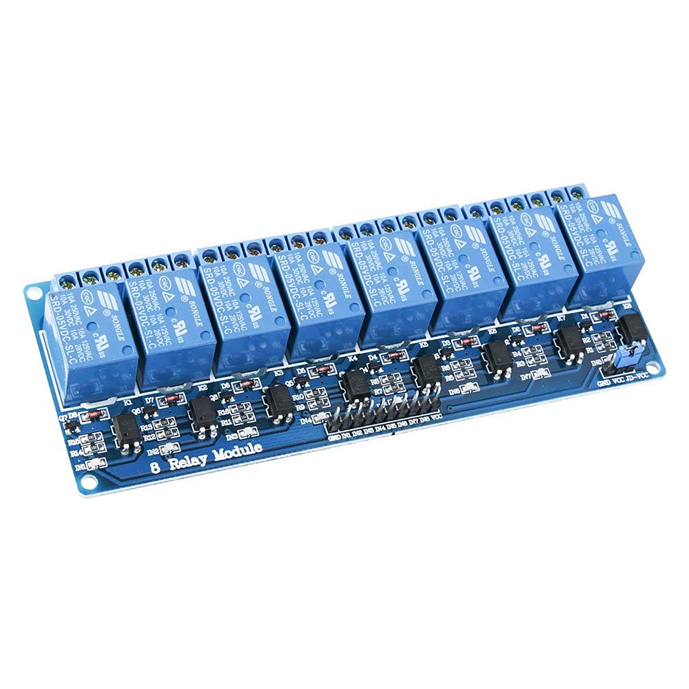
Figure 2: Angled view of the ELEGOO 8-Channel Relay Module, showing relays and input pins.

Figure 3: Top-down view of the module, illustrating component layout and pin labels.
2.2 Power Supply
The module requires a 5V DC power supply. It is recommended to use a separate power supply for the relay coils to prevent interference with the microcontroller, especially when switching high-current loads.
- Shared Power (Default): If the JD-VCC jumper is in place, the relay coils are powered by the same 5V supply as the logic circuit (VCC pin). This is suitable for low-power applications where isolation is not critical.
- Isolated Power: For better stability and to avoid potential noise feedback to the microcontroller, remove the JD-VCC jumper. Connect an external 5V DC power supply to the JD-VCC and GND pins on the module. The VCC pin will still connect to your microcontroller's 5V output to power the optocouplers.

Figure 4: Close-up of the JD-VCC jumper and power input terminals.
2.3 Input Connections (Microcontroller)
Connect the IN1 to IN8 pins of the relay module to the digital output pins of your microcontroller (e.g., Arduino, Raspberry Pi). Each IN pin controls one relay.
- Trigger Level: The module can be configured to trigger on a high (+5V TTL) or low (GND) signal. This is typically set by a jumper on the module (often labeled S1, S2, etc., or indicated by the silkscreen). Refer to the module's silkscreen for specific jumper settings.
- When an input pin (e.g., IN1) receives the trigger signal (high or low, depending on configuration), the corresponding relay will activate.

Figure 5: Relay module connected to an Arduino board.
2.4 Output Connections (Load)
Each relay has three terminals for connecting your load:
- COM (Common): Connect one side of your load's power source here.
- NO (Normally Open): The circuit is open (disconnected) when the relay is inactive. It closes (connects to COM) when the relay is activated.
- NC (Normally Closed): The circuit is closed (connected to COM) when the relay is inactive. It opens (disconnects from COM) when the relay is activated.
Choose between NO and NC depending on whether you want the load to be ON or OFF by default when the relay is not activated.
3. Operation
Once connected, the ELEGOO 8-Channel Relay Module operates by receiving control signals from your microcontroller.
3.1 Relay Activation
To activate a relay, send the appropriate digital signal (HIGH or LOW, depending on your module's trigger configuration) from your microcontroller to the corresponding IN pin. For example, if configured for low-level trigger, sending a LOW signal to IN1 will activate Relay 1.
3.2 Status Indicators
Each relay has an associated LED that illuminates when the relay is activated, providing visual feedback on its status.
3.3 Switching Loads
When a relay activates, its internal switch changes state, connecting COM to NO and disconnecting COM from NC (or vice-versa). This allows you to control AC or DC loads up to the specified current and voltage ratings (230V AC 10A, 30V DC 10A).
Caution: Always ensure the load's voltage and current ratings do not exceed the relay's maximum specifications. Working with AC mains voltage can be dangerous; exercise extreme caution and consult a qualified electrician if unsure.
4. Maintenance
The ELEGOO 8-Channel Relay Module is designed for durability and requires minimal maintenance.
- Keep Clean: Ensure the module is free from dust and debris. Use a soft, dry brush or compressed air for cleaning.
- Environmental Conditions: Operate the module within its specified temperature range (up to 85°C). Avoid exposure to excessive moisture or corrosive environments.
- Connection Integrity: Periodically check all wire connections to ensure they are secure and free from corrosion.
- Component Inspection: Visually inspect the relays and other components for any signs of damage or overheating.
5. Troubleshooting
If you encounter issues with your ELEGOO 8-Channel Relay Module, consider the following troubleshooting steps:
- Relay Not Activating:
- Verify the 5V DC power supply to the module (VCC and GND).
- Check the control signal from your microcontroller to the IN pin. Ensure it's the correct trigger level (HIGH or LOW) as configured.
- Confirm the JD-VCC jumper is correctly set for your power configuration (shared or isolated).
- Test the relay with a simple direct 5V signal to its IN pin and GND to confirm the relay itself is functional.
- Load Not Switching:
- Ensure the relay activates (check the status LED).
- Verify the load connections to the COM, NO, or NC terminals are correct and secure.
- Check the load's power supply.
- Confirm the load's voltage and current are within the relay's specifications.
- Interference or Unstable Operation:
- If experiencing erratic behavior, especially with high-current loads, ensure you are using an isolated power supply for the relay coils (remove JD-VCC jumper and provide external 5V to JD-VCC and GND).
- Ensure proper grounding of all components in your circuit.
- Audible Noise from Relays:
- Relays inherently produce a clicking sound when switching. This is normal.
- If the noise is excessive or constant when it shouldn't be, check for rapid switching or unstable control signals.
6. Technical Specifications
The following table details the technical specifications of the ELEGOO 8-Channel 5V DC Relay Module:
| Feature | Specification |
|---|---|
| Model | FR-EL-SM-005 |
| Brand | ELEGOO |
| Number of Channels | 8 |
| Coil Voltage | 5 Volts DC |
| Coil Resistance | 70 Ohms |
| Drive Current per Channel | ~70mA |
| Max. Switching Voltage (AC) | 250 Volts AC |
| Max. Switching Voltage (DC) | 30 Volts DC |
| Max. Switching Current | 10 Amperes |
| Contact Material | AgCdO |
| Contact Type | Normally Open (NO), Normally Closed (NC) |
| Mounting Type | Through Hole Mount |
| Operating Mode | Automatic |
| Upper Rated Temperature | 85 Degrees Celsius |
| Included Components | 1 x 8-Channel Relay Module |
| Country of Origin | China |
7. Warranty Information
The ELEGOO 8-Channel 5V DC Relay Module comes with a 1-year manufacturer's warranty. Please retain your proof of purchase for warranty claims. For detailed warranty terms and conditions, please refer to the official ELEGOO website or contact customer support.
8. Customer Support
For technical assistance, troubleshooting, or further inquiries regarding your ELEGOO 8-Channel 5V DC Relay Module, please visit the official ELEGOO website or contact their customer support team. You can often find additional resources, tutorials, and FAQs on the brand's support pages.
Manufacturer: ELEGOO
Model: FR-EL-SM-005
ASIN: B06XL1F53G