
1. Introduction
This manual provides detailed instructions for the safe and effective use of the ICstation USB DC-DC Step Up Power Supply Module. This module is designed to convert a low DC input voltage (0.9V-5V) into a stable 5V DC output, primarily for charging or powering USB-compatible devices. Please read this manual thoroughly before installation and operation.
2. Safety Information
Observe the following safety precautions to prevent damage to the module or connected devices, and to ensure personal safety:
- Input Voltage Range: Do not exceed the specified input voltage range of 0.9V to 5V. Applying higher voltage may damage the module.
- Output Current Limit: The maximum output current is 600mA. Exceeding this limit can lead to overheating and damage.
- Polarity: Always ensure correct input polarity (+ and -) when connecting the power source. Incorrect polarity will damage the module.
- Short Circuits: Avoid short circuits on both input and output terminals.
- Environment: Operate the module in a dry, well-ventilated area. Avoid exposure to moisture, dust, and extreme temperatures.
- Handling: Handle the module with care to prevent damage to components.
3. Features
- Input Voltage: 0.9V - 5V DC
- Output Voltage: 5V DC
- Maximum Output Current: 600mA (at 5V output)
- Conversion Efficiency: Up to 96%
- Output Interface: Standard USB Type-A port
- Compact Design: Small form factor for easy integration into projects.
4. Specifications
| Specification | Value |
|---|---|
| Item Model Number | 5V USB DC Step Up Voltage Regulator |
| Input Voltage | 0.9V - 5V DC |
| Output Voltage | 5 Volts DC |
| Max Output Current | 600mA |
| Plug Format | Micro USB (for input) |
| Output Port | USB Type-A |
| Color | Blue |
5. Product Overview
Familiarize yourself with the components and layout of the boost converter module.

Figure 1: Top view of the ICstation USB DC-DC Step Up Power Supply Module, showing the USB output port and main components.

Figure 2: Angled view of the module, highlighting the input solder pads and various electronic components.

Figure 3: Physical dimensions of the module, approximately 1.34 inches by 0.64 inches.
6. Setup and Installation
Follow these steps to properly set up your boost converter module:
- Identify Input Terminals: Locate the '+' and '-' solder pads on the module for DC input. These are typically labeled.
- Connect Input Power: Solder your low voltage DC power source (0.9V-5V) to the input pads. Ensure correct polarity: connect the positive lead of your power source to the '+' pad and the negative lead to the '-' pad. Alternatively, if your power source has a Micro USB output, you can connect it to the Micro USB input port on the module.
- Verify Connections: Double-check all connections for proper polarity and secure soldering to prevent short circuits or loose contacts.
- Connect Output Device: Once the input power is connected, you can plug your USB-powered device into the USB Type-A output port.
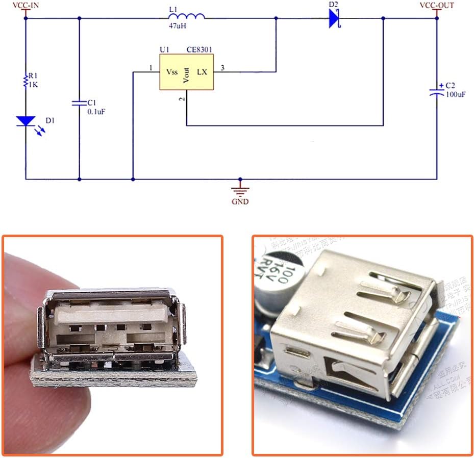
Figure 4: Basic circuit diagram illustrating the input (VCC-IN) and output (VCC-OUT) connections.
7. Operating Instructions
The module operates automatically once a valid input voltage is applied. It will step up the input voltage to a regulated 5V at the USB output port.
- Ensure your input power source can supply sufficient current for the desired output. For example, to achieve 600mA at 5V output, the input current will be higher, especially at lower input voltages (e.g., from a 1V input, the current draw will be significantly higher than 600mA).
- Monitor the temperature of the module during operation, especially when drawing maximum current. Prolonged operation at high loads may cause the module to warm up.
8. Applications
This versatile boost converter can be used in various projects requiring a stable 5V USB power source from low voltage inputs:
- Solar Panel Charger: Convert low voltage output from small solar panels to charge USB devices.

Figure 5: The module connected to a solar panel to provide 5V USB output for charging.
- Portable Power Bank Charging: Use with single-cell lithium-ion batteries or other low voltage battery packs to create a portable USB charging solution.

Figure 6: The module used to charge a power bank from an alternative low voltage source.
- Battery Voltage Boost: Step up voltage from multiple AA/AAA batteries or other low voltage battery configurations to power 5V devices.

Figure 7: The module connected to a series of batteries, boosting their combined voltage to a stable 5V output.
9. Troubleshooting
- No Output Voltage:
- Check input voltage: Ensure it is within the 0.9V-5V range.
- Check input polarity: Verify '+' and '-' connections are correct.
- Check connections: Ensure all wires are securely connected and there are no short circuits.
- Check for damage: Inspect the module for any visible damage to components.
- Output Voltage is Not 5V:
- Check input voltage: If the input voltage is too low or unstable, the output may be affected.
- Check load: Ensure the connected device does not draw more than 600mA. Overloading can cause voltage drop.
- Module Overheating:
- Reduce load: The connected device might be drawing too much current.
- Improve ventilation: Ensure adequate airflow around the module.
- Check for short circuits: A partial short circuit can cause excessive heat.
10. Maintenance
The ICstation USB DC-DC Step Up Power Supply Module requires minimal maintenance:
- Keep the module clean and free from dust and debris.
- Avoid exposing the module to liquids or excessive humidity.
- Store in a cool, dry place when not in use.
11. Warranty and Support
For warranty information or technical support, please refer to the product packaging or contact ICstation customer service directly through their official website or the retailer where the product was purchased. Please have your model number (5V USB DC Step Up Voltage Regulator) and purchase details ready when contacting support.


