1. Introduction
1.1 Safety Information
Please read this manual carefully before installing or using your CATA GI 6004 X gas hob. Keep these instructions for future reference. Incorrect installation, adjustment, alteration, service, or maintenance can cause injury or property damage. Consult a qualified installer, service agency, or the gas supplier for assistance.
- Ensure proper ventilation in the kitchen.
- Do not store flammable materials near the appliance.
- Supervise children when the appliance is in use.
- Do not use the hob as a space heater.
- In case of a gas leak, close the main gas valve, open windows, and do not operate electrical switches.
1.2 Package Contents
Verify that all components are present and undamaged:
- CATA GI 6004 X Gas Hob unit
- Butane gas injectors (pre-installed or included separately for conversion)
- Installation and user manual
- Mounting clips and seals
2. Setup and Installation
Installation must be carried out by a qualified technician in accordance with local regulations and standards.
2.1 Unpacking
Carefully remove the hob from its packaging. Inspect for any damage during transit. Retain packaging for potential future transport or service.
2.2 Cut-out Dimensions
Prepare the countertop opening according to the specified dimensions. Ensure sufficient clearance around the hob for ventilation and maintenance.

Image: Installation diagram illustrating the required countertop cut-out dimensions. The diagram shows a width of 580mm and a depth of 500mm for the hob, with a cut-out of 555mm width and 475mm depth. The hob's height is 45mm.
The required cut-out dimensions for installation are approximately 555 mm (width) x 475 mm (depth).
2.3 Gas Connection
The appliance is prepared for natural gas. Butane gas injectors are included for conversion if required. The gas inlet is located at the rear right of the appliance. Ensure all gas connections are sealed properly and checked for leaks using a soapy water solution.

Image: Rear view of the gas hob, highlighting the gas inlet connection point on the right side. This connection is where the gas supply line should be attached.
2.4 Electrical Connection
Connect the hob to a suitable electrical supply for the integrated electric ignition. Ensure the voltage and frequency match the appliance's requirements as specified on the rating plate.
3. Operating Instructions
3.1 Burner Layout and Power
The CATA GI 6004 X gas hob features four burners with varying power outputs:
- Top Left: Semi-rapid burner, 1.75 kW
- Bottom Left: Rapid burner, 3 kW
- Top Right: Semi-rapid burner, 1.75 kW
- Bottom Right: Auxiliary burner, 1 kW

Image: Overhead view of the CATA GI 6004 X gas hob. It displays four gas burners with cast iron grates and four control knobs located on the right side of the hob.
3.2 Ignition
To ignite a burner:
- Push and turn the corresponding control knob counter-clockwise to the maximum flame position (large flame symbol).
- Hold the knob in for a few seconds. The integrated electric ignition will spark, lighting the gas.
- Once the flame is stable, release the knob. If the flame extinguishes, repeat the process.
3.3 Flame Adjustment
After ignition, you can adjust the flame intensity by turning the control knob between the maximum (large flame symbol) and minimum (small flame symbol) positions. For safety, the knob cannot be turned past the minimum flame position to the 'off' position without pushing it in first.
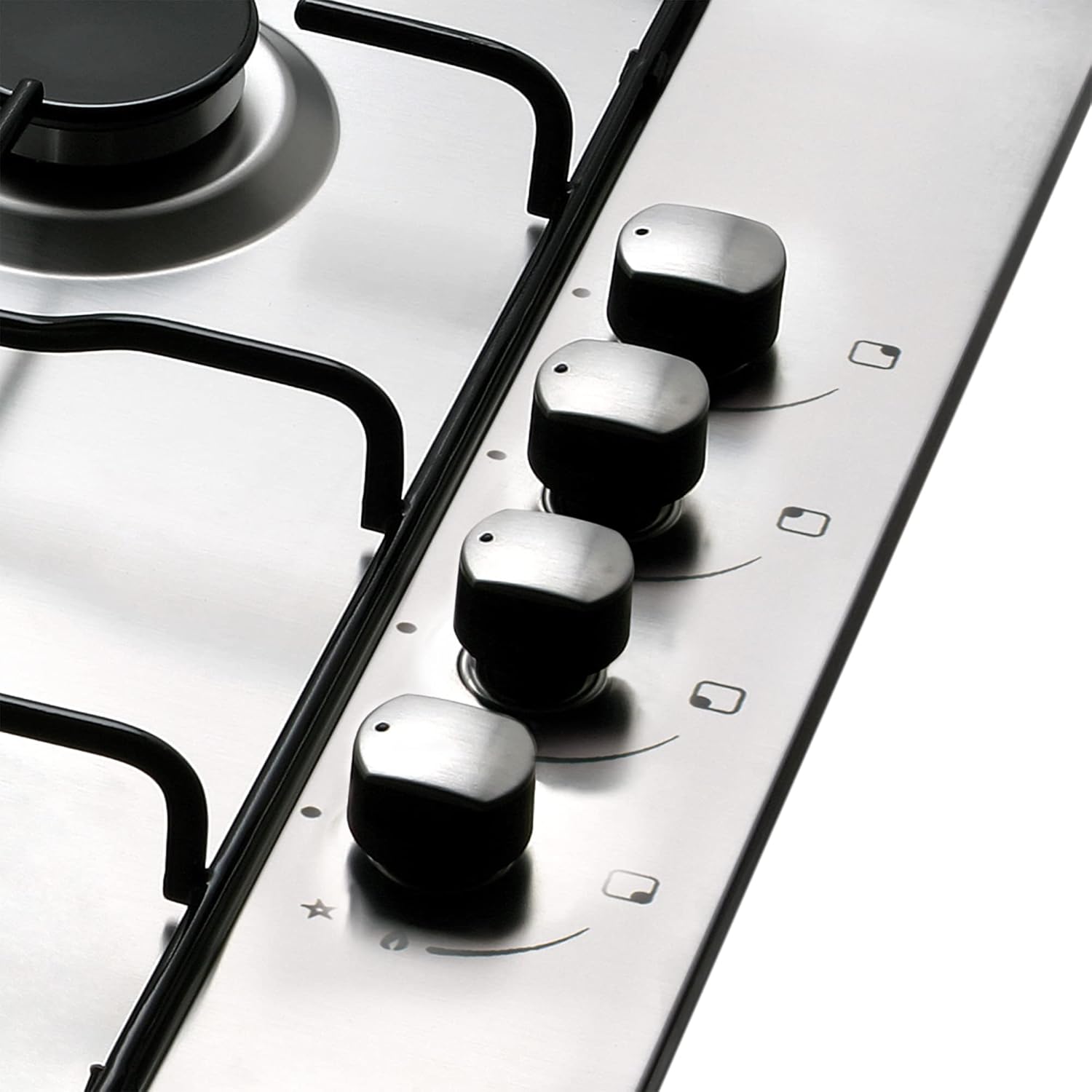
Image: Close-up view of the four control knobs on the right side of the gas hob. Each knob has symbols indicating ignition and flame intensity settings.
4. Maintenance
4.1 General Cleaning
Always ensure the hob is cool before cleaning. Use a soft cloth and mild detergent. Avoid abrasive cleaners, scouring pads, or harsh chemicals that can damage the stainless steel surface or burner components.
4.2 Burner Components
The burner caps and crowns can be removed for cleaning. Wash them in warm soapy water, rinse thoroughly, and dry completely before reassembling. Ensure the burner ports are clear of food debris to maintain efficient flame distribution. The enamelled grill grates can also be cleaned with warm soapy water.
5. Troubleshooting
If you encounter issues with your gas hob, refer to the following common problems and solutions:
| Problem | Possible Cause | Solution |
|---|---|---|
| Burner does not ignite | No gas supply, clogged burner port, faulty ignition, power outage | Check gas supply, clean burner, check power, contact service |
| Flame is irregular or yellow | Clogged burner port, incorrect gas type, improper air mixture | Clean burner, ensure correct gas type (natural/butane), contact service |
| Gas smell detected | Gas leak | Immediately close main gas valve, open windows, do not operate electrical switches, contact gas supplier and service technician |
| Ignition spark is weak or absent | Moisture, food debris, faulty igniter | Ensure igniter is dry and clean, contact service |
6. Technical Specifications
| Feature | Specification |
|---|---|
| Model | GI 6004 X |
| Product Dimensions (D x W x H) | 50 x 58 x 4.5 cm |
| Item Weight | 11 kg |
| Cut-out Dimensions (W x D) | 555 x 475 mm |
| Number of Burners | 4 |
| Burner Power (Top Left) | 1.75 kW (Semi-rapid) |
| Burner Power (Bottom Left) | 3 kW (Rapid) |
| Burner Power (Top Right) | 1.75 kW (Semi-rapid) |
| Burner Power (Bottom Right) | 1 kW (Auxiliary) |
| Total Power | 7.5 kW |
| Fuel Type | Gas (Natural Gas, Butane Gas with included injectors) |
| Ignition Type | Integrated Electronic Ignition |
| Safety Features | Safety Valves |
| Surface Material | Stainless Steel |
| Grill Grates | Enamelled |
| Gas Inlet Position | Rear Right |
7. Warranty and Customer Support
For warranty information, service requests, or technical support, please refer to the warranty card included with your product or contact your retailer. Keep your proof of purchase for warranty claims.


