
1. Introduction
The NOYAFA NF-8200 is a professional cable testing device designed for network and telephone cable installation and maintenance. It features an LCD display for clear readings and offers multiple functions including tone tracing, cable length measurement, and cable mapping for various fault detections. This manual provides detailed instructions for the safe and effective use of your NF-8200 cable tester.

Figure 1: Overview of the NOYAFA NF-8200 Cable Tester components, including the main emitter unit, receiver probe, and remote unit.
2. Safety Information
Please read and understand all safety instructions before operating the device. Failure to follow these instructions may result in electric shock, fire, or damage to the device.
- Do not use the device on live circuits with voltage exceeding AC 60V or DC 42V.
- Ensure batteries are inserted correctly according to polarity markings.
- Do not expose the device to moisture or extreme temperatures.
- Keep the device away from children.
- If the device is damaged, do not attempt to repair it yourself. Contact qualified service personnel.
- Remove batteries if the device will not be used for an extended period.
3. Package Contents
Verify that all items listed below are included in your package:
- NF-8200 Transmitter Unit
- NF-8200 Receiver Unit
- NF-8200 Remote Unit
- Earphone (1 set)
- Battery (2 sets - typically 9V for transmitter, AAA for receiver)
- Telephone Line Adapter (1 set)
- Network Cable Adapter (1 set)
- Cable Clips (1 set)
- User Manual

Figure 2: Contents typically included in the NOYAFA NF-8200 package. Note: Batteries may be supplied separately or not included depending on region.
4. Product Components Overview
4.1. NF-8200 Transmitter Unit
- LCD Screen: Displays test results, settings, and battery status.
- RJ45 Main Port: For connecting network cables for testing.
- RJ11 Port: For connecting telephone cables.
- RJ45 SCAN Port: Used for cable tracing function.
- Power On/Off Button: To turn the unit on or off.
- UP/DOWN Buttons: For navigating menus and adjusting settings.
- PAIR/CALIBRATE Button: Initiates cable pairing tests and calibration.
4.2. NF-8200 Receiver Unit
- Probe: Used to detect the signal from the transmitter.
- LED Light: Assists in working in dark environments.
- Scan Indicator: Visual feedback during tracing.
- Earphone Jack: For connecting earphones for clearer tone detection.
- LED Switch: To turn the LED light on or off.
- Volume Adjust: Controls the audio output level.
- Scan Button: Activates the scanning function.
4.3. NF-8200 Remote Unit
- RJ45 Port: For connecting the far end of a network cable during mapping tests.
- RJ11 Port: For connecting the far end of a telephone cable during mapping tests.
5. Setup
5.1. Battery Installation
- Transmitter Unit: Open the battery compartment cover on the back of the transmitter. Insert one DC 9.0V (NEDA 1604/6F22) battery, ensuring correct polarity. Close the cover securely.
- Receiver Unit: Open the battery compartment cover on the back of the receiver. Insert four 1.5V AAA batteries, ensuring correct polarity. Close the cover securely.
5.2. Initial Power On
Press the 'Power On' button on the transmitter unit. The LCD screen should illuminate, indicating the device is ready for use. Check the battery icon on the LCD to ensure sufficient power.
6. Operating Instructions
6.1. Cable Tracing and Locating
This function helps identify and locate a specific cable among a bundle of cables.
- Connect one end of the target cable to the RJ45 SCAN port on the transmitter unit.
- Turn on the transmitter. Select the 'SCAN' mode using the UP/DOWN buttons.
- Turn on the receiver unit and press its 'Scan' button.
- Move the receiver's probe along the bundle of cables. A distinct tone will be emitted when the probe is near the target cable. Adjust the volume on the receiver as needed.
- The anti-jamming feature helps reduce interference from other electrical signals, providing a clearer tone.

Figure 3: The anti-jamming feature of the NF-8200 helps in accurately tracing cables even in environments with high electrical interference.
6.2. Cable Length Measurement
The NF-8200 can measure the length of LAN and telephone cables up to 2000 meters.
- Ensure the cable to be measured is disconnected from all network devices.
- Connect one end of the cable to the RJ45 Main port (for LAN cable) or RJ11 port (for telephone cable) on the transmitter unit.
- Navigate to the 'LENGTH' or 'MEASURE' mode on the transmitter's LCD using the UP/DOWN buttons.
- Press the 'PAIR/CALIBRATE' button to start the measurement. The LCD will display the cable length in meters.
- The device can also indicate the location of a cable break point.
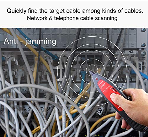
Figure 4: The LCD screen displaying cable length measurement results, indicating open circuits and their approximate distance.
6.3. Cable Mapping (Open, Short, Cross, Crosstalk)
This function checks for wiring errors in network and telephone cables.
- Connect one end of the cable to the RJ45 Main port (for LAN) or RJ11 port (for telephone) on the transmitter unit.
- Connect the other end of the cable to the corresponding port on the remote unit.
- Select the 'WIREMAP' or 'TEST' mode on the transmitter's LCD.
- Press the 'PAIR/CALIBRATE' button to initiate the test.
- The LCD will display the wiring status, indicating any open circuits, short circuits, crossed pairs, or crosstalk issues. The cable map indication will show pin-to-pin connections (e.g., #1-#8 for RJ45, #9 for shield).
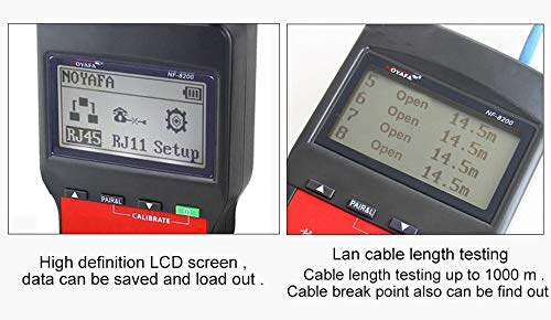
Figure 5: The LCD menu of the NF-8200, showing options for RJ45, RJ11, and setup functions.
6.4. Storage and Memory Functions
The NF-8200 features storage and memory capabilities, allowing users to save and recall test results for later analysis. Refer to the on-screen menu for specific instructions on saving and loading data.
7. Maintenance
- Cleaning: Use a soft, dry cloth to clean the device. Do not use abrasive cleaners or solvents.
- Battery Replacement: Replace batteries when the low battery indicator appears on the LCD. Always use the specified battery types.
- Storage: Store the device in a cool, dry place away from direct sunlight and extreme temperatures. Remove batteries if storing for extended periods to prevent leakage.
8. Troubleshooting
- Device does not power on: Check battery installation and ensure batteries are not depleted. Replace if necessary.
- Inaccurate length measurement: Ensure the cable is completely disconnected from all devices. Calibrate the device if available in the settings.
- No tone during tracing: Check if the transmitter is in SCAN mode and the receiver is turned on with adequate volume. Ensure the cable is properly connected to the RJ45 SCAN port.
- LCD display issues: If the display is dim or flickering, replace the batteries.
9. Specifications
| Feature | Specification |
|---|---|
| Transmitter LCD Screen | 53 x 25 mm |
| Tone Frequency | 1000Hz |
| Cable Testing Range | Less than 2000 m |
| Anti-jamming Tone Mode | 2 tones adjustable |
| Compatible Connectors | RJ11, RJ45 |
| Cable Map Indication | LCD (#1- #8), Shielded indication LCD (#9) |
| Voltage Protection | AC 60V / DC 42V |
| Low Battery Display | LCD (6.5V) |
| Transmitter Battery Type | DC 9.0V (NEDA 1604/6F22 DC9V) x 1PC |
| Transmitter Dimensions (L x W x D) | 185 x 80 x 32 mm |
| Receiver Max Working Current | Less than 70mA |
| Receiver Battery Type | 1.5V x 4PC (AAA) |
| Receiver Dimensions (L x W x D) | 218 x 46 x 29 mm |
| Remote Unit Dimensions (L x W x D) | 107 x 30 x 24 mm |
| Item Weight | 0.7 kg |
10. Application Scope
The NOYAFA NF-8200 is suitable for a wide range of applications, including:
- Network computer room maintenance
- Electronic maintenance and repair
- Telephone cable installation and troubleshooting
- Monitoring system installation
- Broadband network installation
- Internet café maintenance

Figure 6: Various professional environments where the NF-8200 cable tester can be effectively utilized.
11. Warranty and Support
For warranty information and technical support, please refer to the documentation provided with your purchase or contact NOYAFA customer service directly. Keep your purchase receipt as proof of purchase for warranty claims.


