
1. Introduction
The EPsolar Viewstar VS6024BN is a Pulse Width Modulation (PWM) solar charge controller designed for off-grid solar systems. It efficiently manages the charging process of your battery bank from solar panels, ensuring optimal battery health and extending battery lifespan. This controller features an LCD display for easy monitoring and parameter adjustment, supporting 12V and 24V battery systems with automatic voltage recognition.
This manual provides essential information for the safe installation, operation, and maintenance of your VS6024BN solar charge controller.
2. Safety Instructions
- Read all instructions carefully before installation and operation.
- Ensure the battery voltage is sufficient for the controller to recognize the battery type before the first installation.
- Install the controller indoors, away from direct sunlight, high temperature, and humid environments.
- The controller will become hot during operation; ensure adequate ventilation.
- The battery circuit must be protected by a fuse or circuit breaker.
- When connecting the battery, solar panel, and load, always connect the battery first, then the solar panel, and finally the load. Disconnect in the reverse order.
- Ensure all wiring connections are tight to avoid excessive heat from loose connections.
- Wear eye protection when working with batteries.
3. Product Overview
The VS6024BN controller features a robust design with an intuitive interface for monitoring and control.

Figure 1: Front Panel. This image displays the front of the VS6024BN controller, showing the LCD screen, control buttons (Menu, Up, Down, Enter), and the six terminal connections at the bottom for solar panels, battery, and DC load.
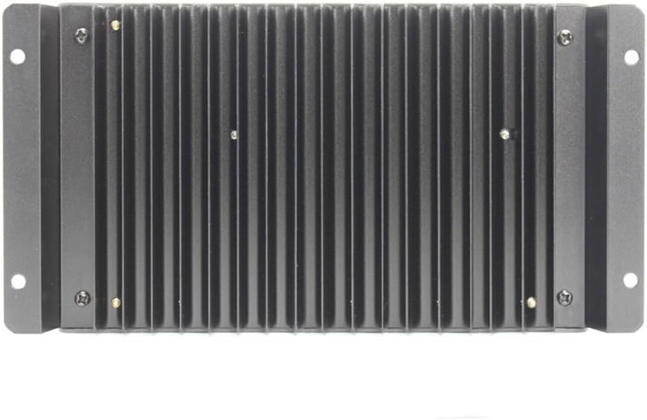
Figure 2: Rear Panel. This image shows the rear of the controller, highlighting the extensive heat sink fins designed for efficient heat dissipation during operation.

Figure 3: Side Panel. This image illustrates the side of the controller, featuring the dedicated ports for the external temperature sensor and the COM (communication) interface, typically an RJ45 port for remote monitoring or PC connection.

Figure 4: Bottom Terminal Connections. This image provides a clear view of the six terminal connections at the bottom of the controller, arranged for connecting solar panels, battery, and DC load.
3.1. Components
- LCD Display: Shows system status, parameters, and error codes.
- Control Buttons: MENU, UP, DOWN, ENTER for navigation and setting adjustments.
- Terminal Blocks: Connections for solar panels, battery, and DC load.
- Temperature Sensor Port: For connecting an external temperature sensor to compensate charging voltage.
- COM Port (RJ45): For communication with a PC or remote display.
- Heat Sink: Located on the rear for thermal management.
4. Setup and Installation
4.1. Mounting
- Choose a well-ventilated, dry, and cool location, away from flammable gases and direct sunlight.
- Mount the controller vertically on a wall or flat surface, ensuring sufficient clearance around the unit for air circulation, especially above and below the heat sink.
- Use appropriate screws to secure the controller through its mounting holes.
4.2. Wiring Sequence
Follow the wiring sequence strictly to prevent damage to the controller or other components.
- Connect the Battery: Connect the battery to the controller's battery terminals (marked with a battery symbol). Ensure correct polarity (+ to + and - to -). The controller will automatically detect the system voltage (12V or 24V).
- Connect the Solar Panel: Connect the solar panel to the controller's solar panel terminals (marked with a solar panel symbol). Ensure correct polarity.
- Connect the DC Load: Connect the DC load to the controller's load terminals (marked with a light bulb symbol). Ensure correct polarity.
Disconnection Sequence: To disconnect the system, reverse the order: disconnect the load first, then the solar panel, and finally the battery.
4.3. External Temperature Sensor (Optional)
If using an external temperature sensor, plug it into the designated port (see Figure 3). Place the sensor near the battery to ensure accurate temperature compensation for charging voltage, which optimizes battery performance and lifespan.
4.4. Communication (Optional)
Connect a communication cable (e.g., RS485 to USB) to the COM port (see Figure 3) for PC monitoring software or a remote display unit.
5. Operating Instructions
5.1. LCD Display
The LCD displays various parameters and status indicators. Press the 'MENU' button to cycle through different display screens, showing information such as battery voltage, solar panel voltage, charging current, load current, and battery temperature.
5.2. Button Functions
- MENU: Cycles through display screens; enters/exits parameter setting mode.
- UP (▲): Increases parameter value; navigates up in menus.
- DOWN (▼): Decreases parameter value; navigates down in menus.
- ENTER (↵): Confirms selection or parameter change.
5.3. Parameter Settings
To adjust parameters (e.g., battery type, load control mode, charging voltages):
- Press and hold the 'MENU' button for 5 seconds to enter parameter setting mode.
- Use 'UP' and 'DOWN' buttons to navigate between parameters.
- Press 'ENTER' to select a parameter for editing.
- Use 'UP' and 'DOWN' to change the value.
- Press 'ENTER' again to confirm the new value.
- Press and hold 'MENU' for 5 seconds to exit setting mode.
Important: Refer to the detailed parameter list in the full product manual for specific values and their functions. Incorrect settings can damage batteries or connected devices.
5.4. Charging Stages (PWM)
The VS6024BN utilizes PWM charging, which typically includes three stages:
- Bulk Charge: Delivers maximum current to rapidly charge the battery.
- Boost Charge: When the battery reaches a set voltage, the controller applies a higher voltage for a limited time to ensure full charge and equalize cells (for flooded batteries).
- Float Charge: Once the battery is fully charged, the voltage is reduced to a lower level to maintain the battery at full capacity and prevent self-discharge.
6. Maintenance
Regular maintenance ensures optimal performance and longevity of your solar charge controller.
- Check Connections: Periodically inspect all wiring connections for tightness and corrosion. Loose connections can cause overheating and damage.
- Clean the Controller: Keep the controller clean and free from dust and debris. Use a dry cloth to wipe the casing. Ensure the heat sink fins are not obstructed.
- Inspect Wiring: Check for any signs of wear, fraying, or damage to the insulation of all cables. Replace damaged cables immediately.
- Monitor Performance: Regularly check the LCD display for normal operation and expected charging/discharging values. Note any unusual readings.
- Battery Inspection: For flooded lead-acid batteries, check electrolyte levels and specific gravity regularly.
7. Troubleshooting
This section addresses common issues you might encounter with your VS6024BN controller.
| Problem | Possible Cause | Solution |
|---|---|---|
| No display on LCD | Battery not connected or reverse polarity; battery voltage too low. | Check battery connections and polarity. Ensure battery voltage is above 8V. |
| Battery not charging | Solar panel not connected or reverse polarity; solar panel voltage too low; open circuit in solar array. | Check solar panel connections and polarity. Ensure sufficient sunlight. Verify solar panel voltage. |
| Load not working | Load not connected or reverse polarity; load current exceeds controller rating; battery voltage too low (LVD). | Check load connections and polarity. Reduce load or use a larger controller. Charge battery. |
| Over-voltage protection | Solar panel voltage too high. | Ensure solar panel open circuit voltage (Voc) does not exceed the controller's maximum input voltage. |
| Over-current protection | Load current exceeds controller rating. | Reduce the connected load. |
8. Specifications (VS6024BN)
The following table details the technical specifications for the EPsolar Viewstar VS6024BN PWM Solar Charge Controller.

Figure 5: Model Specifications. This image presents a comparative table of specifications for various Viewstar models, with the VS6024BN column providing detailed electrical parameters relevant to this manual.
| Parameter | Value |
|---|---|
| Nominal System Voltage | 12V / 24V Auto Work |
| Rated Battery Current | 60A |
| Rated Load Current | 60A |
| Max. Battery Voltage | 32V |
| Equalize Charging Voltage (Sealed) | 14.6V |
| Equalize Charging Voltage (Flooded) | 14.8V |
| Equalize Charging Voltage (User-defined) | 9-17V |
| Boost Charging Voltage (Gel) | 14.2V |
| Boost Charging Voltage (Sealed) | 14.4V |
| Boost Charging Voltage (Flooded) | 14.6V |
| Boost Charging Voltage (User-defined) | 9-17V |
| Float Charging Voltage (Gel/Sealed/Flooded) | 13.8V |
| Float Charging Voltage (User-defined) | 9-17V |
| Low Voltage Reconnect Voltage (Gel/Sealed/Flooded) | 12.6V |
| Low Voltage Reconnect Voltage (User-defined) | 9-17V |
| Low Voltage Disconnect Voltage (Gel/Sealed/Flooded) | 11.1V |
| Low Voltage Disconnect Voltage (User-defined) | 9-17V |
| Self-consumption (12V) | ≤15mA |
| Self-consumption (24V) | ≤10mA |
| Grounding | Common Negative |
| Temperature Compensation | -3mV/°C/2V |
| Communication | RS485 / RJ45 Interface |
| Product Dimensions | 8.07 x 5.12 x 2.76 inches |
| Item Weight | 2.87 pounds |
| Display Type | LCD |
| Color | Black |
9. Warranty and Support
This product is covered by a standard manufacturer's warranty against defects in materials and workmanship. Please refer to the warranty card included with your purchase for specific terms and conditions, including the warranty period and coverage details.
For technical support, troubleshooting assistance, or warranty claims, please contact your retailer or the manufacturer directly. Contact information can typically be found on the product packaging or the manufacturer's official website.


