Important Safety Information
WARNING: Installation and servicing of this furnace control board must be performed by a qualified service technician. Failure to follow these instructions could result in property damage, personal injury, or death.
- Disconnect all power to the furnace before installing or servicing this control board.
- Verify all wiring connections are secure and correct according to the furnace manufacturer's specifications.
- Do not bypass any safety devices.
- Ensure proper grounding.
Product Overview
The Amana 50A51-215 is an OEM replacement two-stage integrated furnace control board designed for specific Amana furnace models. It manages the ignition sequence, monitors safety limits, and controls the furnace's operational cycles.
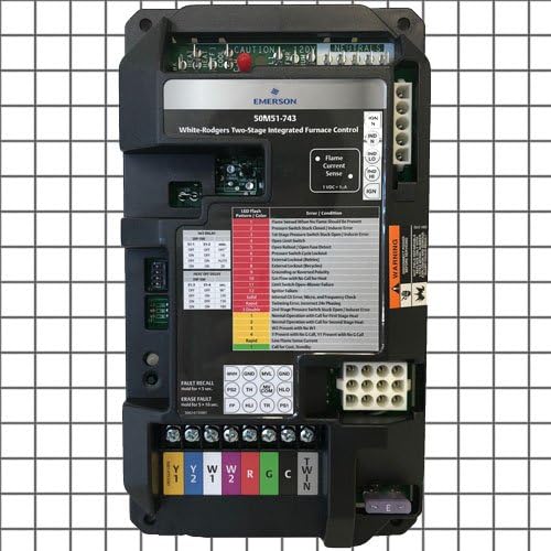
Figure 1: Amana 50A51-215 Furnace Control Board. This image displays the front view of the control board, showing various terminals, connectors, LED indicators, and labels for components like "Flame Current Sense" and "Fault Recall."
Key Components
- Terminal Blocks: For connecting power, thermostat wires (Y1, Y2, W, R, G, C), and other furnace components.
- LED Indicators: Provide diagnostic feedback through flash patterns and colors.
- Flame Current Sense: Monitors the presence of a flame during operation.
- Fault Recall Button: Used to retrieve stored fault codes.
- Erase Fault Button: Used to clear stored fault codes.
Setup and Installation
This section provides general guidelines. Always refer to the specific furnace manufacturer's service manual for detailed installation instructions.
- Power Disconnection: Turn off all electrical power to the furnace at the main service panel.
- Access Control Board: Locate and open the furnace access panel to expose the existing control board.
- Document Wiring: Carefully label all wires connected to the old control board before disconnecting them. Take photographs for reference if necessary.
- Remove Old Board: Disconnect all wires and mounting screws, then remove the old control board.
- Install New Board: Mount the new Amana 50A51-215 control board in the same location using the existing mounting hardware.
- Connect Wiring: Reconnect all wires to the new board, ensuring each wire is attached to its corresponding terminal as documented in step 3. Pay close attention to the "CAUTION 120V" and "NEUTRALS" connections, as well as thermostat wires (Y1, Y2, W, R, G, C).
- Verify Connections: Double-check all wiring for correctness and secure connections.
- Restore Power: Close the furnace access panel and restore electrical power to the furnace.
- Test Operation: Initiate a heating cycle to verify proper furnace operation.
Operating Instructions
Once installed, the control board operates automatically in conjunction with your thermostat to manage the furnace's heating cycles.
LED Indicator
The integrated LED on the control board provides status and diagnostic information. During normal operation, the LED will typically flash slowly. Refer to the Troubleshooting section for specific flash patterns and their meanings.
Fault Recall
To recall the last stored fault code, press and hold the FAULT RECALL button for approximately 2 seconds. The LED will then display the fault code.
Erase Fault
To erase all stored fault codes, press and hold the ERASE FAULT button for approximately 5 seconds.
Maintenance
The Amana 50A51-215 control board itself requires no routine maintenance. However, regular maintenance of the entire furnace system is crucial for its longevity and efficient operation.
- Ensure furnace filters are replaced or cleaned regularly according to the furnace manufacturer's recommendations.
- Have the furnace inspected and serviced annually by a qualified technician.
- Keep the area around the furnace clear of obstructions and combustible materials.
Troubleshooting
The LED indicator on the control board provides diagnostic codes to assist in troubleshooting. Observe the flash pattern and color, then refer to the table below.
| LED Flash Pattern / Color | Condition |
|---|---|
| 1 Red Flash | Flame Sense Current When No Flame Should Be Present |
| 2 Red Flashes | Pressure Switch Stuck Closed | Inducer Error |
| 3 Red Flashes | 1st Stage Pressure Switch Stuck Open | Inducer Error |
| 4 Red Flashes | Open Limit Switch |
| 5 Red Flashes | Open Rollout | Open Fuse Detect |
| 6 Red Flashes | Pressure Switch Cycle Lockout |
| 7 Red Flashes | Ignition Lockout |
| 8 Red Flashes | External Lockout (Recycled) |
| 9 Red Flashes | Grounding or Reversed Polarity |
| 10 Red Flashes | Call for Heat with No Call for Heat |
| 11 Red Flashes | Limit Switch Open - Motor Failure |
| 12 Red Flashes | Ignition Failure |
| 13 Red Flashes | Invalid Line Voltage, Micro, and Frequency Check |
| 14 Red Flashes | Blower Error, Incorrect Idle Proving |
| 15 Red Flashes | 2nd Stage Pressure Switch Stuck Open | Inducer Error |
| 1 Yellow Flash | Normal Operation with Call for First Stage Heat |
| 2 Yellow Flashes | Normal Operation with Call for Second Stage Heat |
| 3 Yellow Flashes | Call for Heat |
| 4 Yellow Flashes | 1st Stage Heat with No C-Call, Y1 Present with No C-Call |
| 5 Yellow Flashes | Low Flame Sense Current |
| Rapid Yellow Flashes | Call for Cool, Humidity |
If troubleshooting steps do not resolve the issue, contact a qualified HVAC technician.
Specifications
- Model: 50A51-215
- Type: OEM Replacement Furnace 2 Stage Control Circuit Board
- Manufacturer: Amana
- Product Dimensions: 9 x 7 x 10 inches
Warranty and Support
For specific warranty information, please refer to the documentation provided with your purchase or contact Amana customer support.
For technical assistance or service, it is recommended to contact a certified HVAC professional.


