1. Product Overview
The UHPPOTE UT0611-05 is a robust push-to-exit button constructed from durable zinc alloy, designed for integration into various access control systems. It provides a momentary contact closure with Normally Open (NO) and Common (COM) outputs, enabling the release of an electric lock or signaling an access control panel to grant egress. Its flush-mounting design ensures a discreet and secure installation.

Image 1.1: Front view of the UHPPOTE UT0611-05 Zinc Alloy Push To Exit Button, showcasing its sleek design and central push mechanism.
2. Safety Information
- Always disconnect power to the access control system before attempting any installation, wiring, or maintenance procedures.
- Installation should be performed by qualified personnel familiar with electrical wiring and access control systems.
- Ensure correct wiring connections to prevent damage to the device, connected equipment, or potential electrical hazards.
- This device operates on 12V DC. Verify that your power supply is compatible and provides the correct voltage.
- Do not expose the device to excessive moisture or extreme temperatures.
3. Specifications
| Feature | Specification |
|---|---|
| Model Number | UT0611-05 |
| Material | Zinc Alloy |
| Output Type | NO/COM (Normally Open / Common) |
| Durability | Rated for 50,000 continuous clicking tests |
| Mounting Type | Flush Mounting |
| Power Source | DC |
| Voltage | 12 Volts |
| Product Dimensions | 3.25 x 1.25 x 1 inches (approx. 8.25 x 3.17 x 2.54 cm) |
| Item Weight | 2.4 ounces (approx. 68 grams) |
4. Package Contents
- 1 x UHPPOTE UT0611-05 Push To Exit Button
Note: Mounting screws are not included and must be sourced separately.
5. Installation and Setup
Follow these steps for proper installation of your push-to-exit button:
- Prepare Mounting Location: Select a suitable location for flush mounting, typically near the door on the secure side. Create a cutout in the wall or door frame that accommodates the dimensions of the button's housing.
- Secure Housing: Insert the button assembly into the prepared opening. Secure the housing firmly using appropriate mounting screws (not included) through the designated mounting holes.
- Connect Wiring: Refer to the "6. Wiring Diagram" section for detailed connection instructions. Connect the NO (Normally Open) and COM (Common) terminals of the button to your access control system or electric lock. Ensure all connections are tight and insulated.
- Test Functionality: After securing the button and completing all wiring, restore power to the system. Test the button's operation by pressing it to ensure it correctly triggers the connected access control device or electric lock.

Image 5.1: View of the push-to-exit button with its internal wiring terminals exposed, showing the connection points for the access control system.

Image 5.2: Disassembled view of the push-to-exit button, illustrating the robust zinc alloy housing and the internal button mechanism.
6. Wiring Diagram
The UHPPOTE UT0611-05 push-to-exit button features Normally Open (NO) and Common (COM) contacts. When the button is pressed, the NO and COM contacts close, completing an electrical circuit. This action is typically used to momentarily interrupt power to a fail-safe electric lock (causing it to unlock) or to send a signal to an access control panel to release a door.
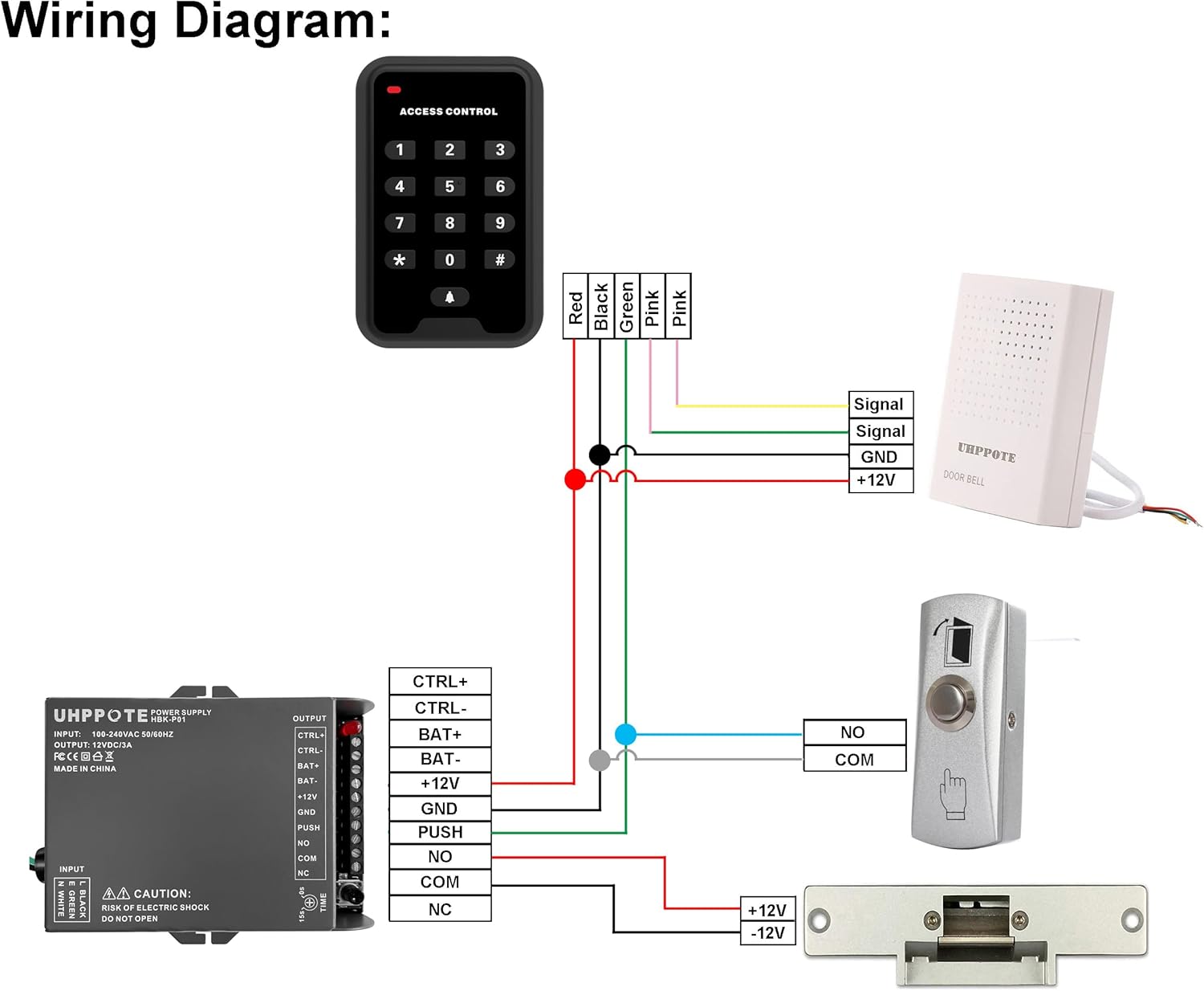
Image 6.1: Comprehensive wiring diagram illustrating the connection of the push-to-exit button (labeled 'PUSH') to an access control power supply and an electric lock. The diagram shows the NO and COM terminals connecting to the 'PUSH' input on the power supply.
Connection Points:
- NO (Normally Open): This terminal is open (no continuity) with the COM terminal when the button is not pressed. It closes (has continuity) with COM when the button is pressed.
- COM (Common): This is the common terminal for the switch.
Connect the NO and COM terminals of the exit button to the corresponding 'PUSH' or 'EXIT' input terminals on your access control panel or power supply unit. Ensure polarity is observed if specified by your access control system.
7. Operation
Operating the UHPPOTE UT0611-05 push-to-exit button is straightforward:
- To exit the secured area, simply press the button.
- The button provides a momentary contact closure, meaning the connected electric lock or access control system will be activated only while the button is held down.
- Release the button to return the contacts to their normally open state.
8. Maintenance
The UHPPOTE UT0611-05 push-to-exit button requires minimal maintenance to ensure long-term performance:
- Cleaning: Periodically clean the button surface and housing with a soft, dry, or slightly damp cloth. Avoid using abrasive cleaners, solvents, or harsh chemicals, as these can damage the finish.
- Inspection: Regularly inspect the wiring connections for any signs of wear, corrosion, or loose connections. Ensure all screws are tight.
- Functionality Check: Periodically test the button's operation to confirm it activates the access control system as expected.
9. Troubleshooting
If you encounter issues with your push-to-exit button, refer to the following troubleshooting steps:
- Button Not Responding:
- Verify that the access control system and associated power supply are receiving power.
- Check all wiring connections between the button, power supply, and electric lock/access control panel. Ensure they are secure and correctly wired according to the diagram in Section 6.
- Ensure the button's NO and COM terminals are correctly connected to the designated input on your access control device.
- Door Remains Unlocked/Locked (Incorrect Behavior):
- Confirm the type of electric lock being used (fail-safe or fail-secure) and ensure the wiring configuration matches its requirements. A fail-safe lock unlocks when power is removed, while a fail-secure lock remains locked when power is removed.
- If possible, use a multimeter to test the continuity of the button's NO and COM contacts. When pressed, there should be continuity; when released, there should be none.
10. Warranty and Support
For specific warranty information, technical assistance, or to report any issues with your UHPPOTE UT0611-05 push-to-exit button, please contact UHPPOTE customer service through their official website or authorized support channels. Please retain your purchase receipt as proof of purchase for any warranty claims.


