
1. Introduction
This manual provides comprehensive instructions for the installation, operation, and maintenance of the Juniper Networks EX4200-48PX Ethernet Switch. The EX4200-48PX is a high-performance, managed, stackable switch designed for enterprise access and aggregation deployments. It features 48 Gigabit Ethernet ports with Power over Ethernet Plus (PoE+) capabilities, ensuring reliable connectivity and power delivery for various network devices.
Key features include Layer 2 and Layer 3 switching, support for various data transfer protocols, and advanced security and management capabilities. Please read this manual thoroughly before operating the device to ensure proper setup and safe usage.
2. Safety Information
Observe the following safety precautions to prevent injury and damage to the equipment:
- Electrical Safety: Ensure the power source matches the switch's voltage requirements (100-240V~50-60 Hz 12A). Use only the provided power cord or an approved replacement.
- Grounding: Always ensure the switch is properly grounded to prevent electrical shock.
- Ventilation: Do not block ventilation openings. Ensure adequate airflow around the device to prevent overheating.
- Environment: Operate the switch in a clean, dry environment within specified temperature and humidity ranges. Avoid exposure to moisture or extreme temperatures.
- Handling: The switch is heavy (approximately 25 pounds). Use proper lifting techniques or assistance when moving it.
3. Package Contents
Carefully unpack the box and verify that all items are present and in good condition. If any item is missing or damaged, contact your vendor immediately.

Figure 3.1: Juniper EX4200-48PX switch as received in its packaging, including the switch unit, a power cable, and a network cable.
- Juniper EX4200-48PX Switch Unit
- Power Cord
- Ethernet Cable
- Rack-mount Kit (typically includes brackets and screws)
- Documentation (Quick Start Guide, Safety Information)
4. Physical Description
4.1. Front Panel
The front panel of the EX4200-48PX switch features 48 Gigabit Ethernet ports, status indicators, and a small LCD display for local management and status monitoring.

Figure 4.1: Front view of the Juniper EX4200-48PX switch, highlighting the 48 Gigabit Ethernet ports.

Figure 4.2: Detail of the front panel showing the LCD display and status indicators: ALM (Alarm), SYS (System), and MST (Master). These LEDs provide quick visual status of the device's operational state.
4.2. Product Label
The product label, typically located on the chassis, provides essential identification details for the switch.
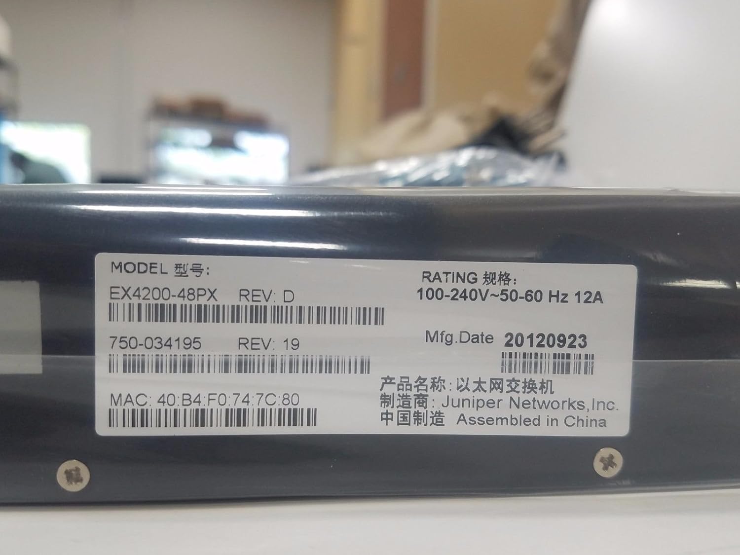
Figure 4.3: Product label displaying the Model: EX4200-48PX REV: D, Rating: 100-240V~50-60 Hz 12A. Key identifiers include the MAC address: 40:B4:F0:74:7C:80, Part Number: 750-034195 REV: 19, and Manufacturing Date: 20120923. The device is manufactured by Juniper Networks, Inc. and assembled in China.
4.3. Rack Mounting Brackets
The switch is designed for rack installation, utilizing standard rack-mount ears.

Figure 4.4: A close-up view of a rack mount ear, demonstrating the attachment point for securing the switch within a standard equipment rack.
5. Setup
5.1. Rack Installation
- Attach the provided rack-mount brackets to the sides of the switch using the screws supplied in the rack-mount kit.
- Align the switch with the rack posts and secure it using appropriate rack screws. Ensure the switch is level and firmly seated.
5.2. Connecting Power
- Connect one end of the power cord to the AC power inlet on the rear panel of the switch.
- Connect the other end of the power cord to a grounded AC power outlet.
- The switch features a redundant internal power supply for enhanced reliability.
5.3. Connecting Network Devices
- Connect Ethernet cables from your network devices (computers, IP phones, wireless access points) to the 48 Gigabit Ethernet ports on the front panel.
- For devices requiring Power over Ethernet (PoE+), ensure they are compatible and connect them to any of the 48 ports. The switch will automatically detect and provide power.
- For uplink connections to other switches or routers, use appropriate Ethernet cables.
5.4. Initial Configuration (Optional)
For initial configuration or advanced management, connect a console cable (not typically included) to the console port (usually RJ-45) on the front or rear panel and connect it to a computer. Use a terminal emulation program to access the command-line interface (CLI).
6. Operating the Switch
6.1. Powering On/Off
- Power On: Once the power cord is connected, the switch will typically power on automatically. Observe the system LEDs.
- Power Off: To power off, disconnect the power cord from the AC outlet. For controlled shutdown, it is recommended to gracefully shut down the operating system via the CLI if possible, before disconnecting power.
6.2. Understanding LED Indicators
The front panel LEDs provide critical status information:
- ALM (Alarm): Indicates system alarms or critical errors. Refer to the CLI or system logs for details.
- SYS (System): Indicates the overall system status. Typically solid green for normal operation.
- MST (Master): Indicates if the switch is operating as the master in a Virtual Chassis configuration.
- Port LEDs: Each Ethernet port has LEDs indicating link status and activity.
7. Maintenance
- Cleaning: Periodically clean the exterior of the switch with a soft, dry cloth. Do not use liquid or aerosol cleaners. Ensure ventilation openings are free of dust and debris.
- Firmware Updates: Regularly check the Juniper Networks support website for firmware updates. Applying updates can improve performance, add features, and address security vulnerabilities. Follow the manufacturer's instructions for firmware upgrade procedures.
- Environmental Monitoring: Ensure the operating environment remains within the specified temperature and humidity ranges to prolong the life of the device.
8. Troubleshooting
This section provides basic troubleshooting steps for common issues.
8.1. No Power
- Verify the power cord is securely connected to both the switch and the AC outlet.
- Check if the AC outlet is functional by plugging in another device.
- Ensure the power supply is receiving power (check for any power supply LEDs if available).
8.2. No Link on Port
- Check the Ethernet cable for damage and ensure it is properly seated at both ends.
- Verify the connected device is powered on and functioning correctly.
- Check the port configuration on the switch (e.g., speed, duplex settings) via the CLI.
8.3. Network Connectivity Issues
- Check the SYS LED for any alarm indications.
- Verify IP addressing and subnet mask configurations on connected devices and the switch.
- Ensure routing is correctly configured if devices are on different subnets.
- Consult the Juniper Networks documentation for advanced troubleshooting or contact technical support.
9. Specifications
The following table outlines the key specifications for the Juniper EX4200-48PX switch:
| Feature | Description |
|---|---|
| Model | EX4200-48PX |
| Brand | Juniper Networks |
| Number of Ports | 48 |
| Interface Type | PoE+ (Power over Ethernet Plus) |
| Data Transfer Rate | 1000 Megabits Per Second (Gigabit Ethernet) |
| Switching Capacity | Layer 2, Layer 3 |
| Power Supply | Redundant - Internal |
| Features | 256-bit encryption, ARP support, Auto-uplink (auto MDI/MDI-X), DHCP proxy/server/snooping/support, DoS attack prevention, Dynamic ARP Inspection (DAI), Graceful Route Engine Switchover (GRES), High Availability, Hot swap module replacement, IGMP snooping, IPv6 support, Jumbo Frames support, MPLS support, Non-Stop Bridging (NSB), Non-Stop Routing (NSR), Quality of Service (QoS), RADIUS support, Redundant trunk group (RTG), Routing, Store and forward, Syslog support, Temperature sensor, Time Domain Reflectometry (TDR), Virtual Chassis technology, VLAN support. |
| Material | Metal |
| Item Weight | 25 pounds |
| UPC | 695087049426 |
| Manufacturer | Juniper |
| First Available Date | April 10, 2017 |
10. Warranty and Support
The Juniper EX4200-48PX switch is covered by a manufacturer's warranty. For specific warranty terms and conditions, please refer to the documentation provided with your purchase or visit the official Juniper Networks website.
For technical support, product documentation, and software downloads, please visit the Juniper Networks support portal. Ensure you have your product model and serial number available when contacting support.

