
1. Introduction
This manual provides instructions for the installation, operation, and maintenance of the Caleffi 2035 Thermostatic Control with Contact Probe. This device is designed for liquid temperature limitation in conjunction with thermostatic radiator valves.
The Caleffi 2035 is a thermostatic control unit featuring a contact probe and a 2-meter capillary tube. It is specifically engineered for use with Caleffi valve series 338, 339, 401, 402, 455, 220, 221, 222, 223, 224, 225, 226, and 227.
2. Setup and Installation
The Caleffi 2035 Thermostatic Control is intended for professional installation. Ensure all local codes and regulations are followed during installation.
2.1 Components Overview
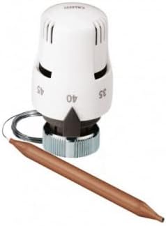
Figure 1: Caleffi 2035 Thermostatic Control unit with the white control head, metal connection nut, and copper contact probe attached via a coiled capillary tube.
The image above displays the main components: the thermostatic control head (white), the connection mechanism, and the contact probe (copper-colored) connected by a capillary tube.
2.2 Installation Steps
- Prepare the Valve: Ensure the compatible thermostatic radiator valve (e.g., Caleffi series 338, 339, 401, 402, 455, 220-227) is correctly installed in the heating system.
- Attach the Control Head: Carefully align the thermostatic control head with the valve body. Securely fasten the control head to the valve using the provided connection mechanism. Ensure a tight, leak-free connection.
- Position the Contact Probe: The contact probe is designed to measure the temperature of the liquid. Position the probe in direct contact with the pipe or surface where liquid temperature limitation is required. The 2-meter capillary tube allows for flexible placement.
- Secure the Capillary Tube: Route and secure the capillary tube to prevent damage or interference with other components. Avoid sharp bends or kinks in the tube.
- Initial Check: After installation, visually inspect all connections for proper seating and ensure the probe is correctly positioned.
3. Operating Instructions
The Caleffi 2035 Thermostatic Control allows for precise adjustment of the liquid temperature limitation.
3.1 Temperature Setting
- The control head features a temperature scale. Rotate the control head to align the desired temperature setting with the indicator mark.
- The adjustable temperature range for this device is 40 °C to 90 °C.
- Select the temperature setting that corresponds to the required liquid temperature limitation for your system.
The thermostatic control will automatically regulate the flow through the valve to maintain the liquid temperature at the set point, as measured by the contact probe.
4. Maintenance
The Caleffi 2035 Thermostatic Control is designed for reliable operation with minimal maintenance. Regular checks can help ensure optimal performance.
- Visual Inspection: Periodically inspect the control head, capillary tube, and contact probe for any signs of damage, corrosion, or loose connections.
- Cleaning: If necessary, gently clean the exterior of the control head and probe with a soft, damp cloth. Do not use abrasive cleaners or solvents.
- Probe Contact: Ensure the contact probe remains firmly in contact with the surface it is monitoring to guarantee accurate temperature readings.
For any complex maintenance or repairs, it is recommended to consult a qualified technician.
5. Troubleshooting
If you experience issues with your Caleffi 2035 Thermostatic Control, consider the following common checks:
- Incorrect Temperature:
- Verify that the temperature setting on the control head is correct.
- Ensure the contact probe is properly positioned and making good thermal contact with the pipe or surface.
- Check for any obstructions or insulation issues around the probe that might affect temperature sensing.
- No Regulation:
- Confirm that the control head is securely attached to the valve.
- Inspect the capillary tube for any damage, kinks, or leaks.
- Ensure the compatible valve is functioning correctly.
- Physical Damage: If any part of the unit (control head, capillary tube, or probe) appears physically damaged, replacement may be necessary.
If the problem persists after performing these checks, contact a qualified heating system technician for further assistance.
6. Specifications
Key technical specifications for the Caleffi 2035 Thermostatic Control:
| Feature | Detail |
|---|---|
| Brand | Caleffi |
| Model Number | 2035 |
| Part Number | 203702 |
| Product Dimensions | 10 x 20 x 116 cm |
| Weight | 3 kg |
| Capillary Tube Length | 2 meters |
| Temperature Range | 40 °C to 90 °C |
| Compatible Valve Series | 338, 339, 401, 402, 455, 220, 221, 222, 223, 224, 225, 226, 227 |
| Batteries Required | No |
7. Warranty and Support
Specific warranty terms and detailed support contact information are not provided within this manual. For warranty inquiries or technical support, please refer to the product packaging, purchase documentation, or contact Caleffi directly through their official website or customer service channels.


