1. Introduction
This manual provides essential information for the proper installation, operation, and maintenance of the Johnson Controls FA-VAV111-1 HVAC Controller Facilitator. This device is a critical component in HVAC control systems, designed to manage and facilitate various functions within a building's heating, ventilation, and air conditioning infrastructure. Adherence to these instructions is crucial for optimal performance and safety.
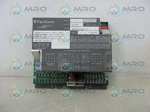
Figure 1: Front view of the Johnson Controls FA-VAV111-1 HVAC Controller Facilitator.
2. Safety Information
Always observe standard safety precautions when working with electrical equipment. Installation and servicing should only be performed by qualified personnel. Disconnect all power to the unit and associated equipment before performing any installation, maintenance, or troubleshooting procedures.
- Ensure power supply matches the device's specifications (24 VAC, Class 2).
- Avoid contact with live electrical components.
- Proper grounding procedures must be followed.
- Protect the device from moisture and extreme temperatures.
3. Product Overview
The FA-VAV111-1 is a 2 Amp, 24 VAC, Class 2 Controller Facilitator designed for integration into HVAC control systems. It functions as an HVAC Control System Board, providing necessary interfaces and control logic for various system components. Key features include:
- 2 Amp current rating.
- 24 VAC power input, Class 2.
- Binary Output (BIN OUT): 24 VAC, Class 2, 0.5A Pilot Duty.
- Analog Output (ANA OUT): 0-10 VDC, Class 2, 0.01A.
4. Setup and Installation
Careful installation is essential for the reliable operation of the FA-VAV111-1 controller. Refer to the detailed wiring diagrams and system schematics provided with your specific HVAC system for precise connection points.
4.1 Mounting
Mount the controller in a secure, dry location, free from excessive vibration and within its specified operating temperature range. Ensure adequate ventilation around the unit to prevent overheating. Use appropriate fasteners for mounting to a stable surface.
4.2 Electrical Connections
All wiring must comply with local and national electrical codes. Use appropriate wire gauges for all connections.
- Power Input: Connect the 24 VAC, Class 2 power supply to the designated power input terminals. The unit requires a 2 Amp supply.
- Binary Outputs (BIN OUT): Connect control devices requiring 24 VAC, 0.5A pilot duty to the binary output terminals.
- Analog Outputs (ANA OUT): Connect devices requiring 0-10 VDC, 0.01A analog signals to the analog output terminals.
- Analog Inputs: Connect sensors or other devices providing analog input signals to the analog input terminals. Refer to the device label for specific input types (e.g., TEMP, 2VDC, 10VDC).
- Binary Inputs: Connect switches or other devices providing binary input signals to the binary input terminals.

Figure 2: Side view illustrating the various connection terminals for inputs and outputs.

Figure 3: Bottom view detailing additional connection points and component layout.

Figure 4: Close-up of the product label, showing model number, power ratings, and output specifications.
5. Operating Instructions
The Johnson Controls FA-VAV111-1 operates as a facilitator within a larger HVAC control system. Its specific operational parameters and control logic are determined by the programming of the overall system. Once properly installed and powered, the unit will execute the programmed control sequences based on its inputs and generate the corresponding outputs.
- Ensure all connected devices are functioning correctly.
- Monitor system performance through the main HVAC control interface.
- The 0-10 VDC analog output provides proportional control signals to compatible devices.
- The 24 VAC binary outputs are used for on/off control of pilot duty loads.
6. Maintenance
The FA-VAV111-1 controller is designed for reliable operation with minimal maintenance. However, periodic checks can help ensure longevity and prevent system failures.
- Visual Inspection: Periodically inspect the unit for any signs of physical damage, loose connections, or dust accumulation.
- Cleaning: If necessary, gently clean the exterior of the unit with a soft, dry cloth. Do not use liquid cleaners or solvents. Ensure power is disconnected before cleaning.
- Connection Integrity: Verify that all wiring connections remain secure and free from corrosion.
- Environmental Conditions: Ensure the operating environment remains within specified temperature and humidity limits.
7. Troubleshooting
If the FA-VAV111-1 controller or the associated HVAC system is not functioning as expected, consider the following troubleshooting steps:
- No Power: Check the 24 VAC power supply. Ensure the circuit breaker or fuse is not tripped. Verify all power connections are secure.
- Incorrect Output: Verify the input signals to the controller are correct. Check the wiring to the output devices. Ensure the output device itself is functional.
- System Malfunction: If the entire HVAC system is not responding, consult the overall system's diagnostic tools and documentation. The FA-VAV111-1 is a component; issues may originate elsewhere in the control network.
- Loose Connections: Inspect all terminal connections for tightness and proper seating.
- Environmental Factors: Ensure the unit is not exposed to extreme heat, cold, or moisture.
If problems persist after performing these checks, contact qualified service personnel or Johnson Controls technical support.
8. Specifications
| Parameter | Value |
|---|---|
| Model Number | FA-VAV111-1 |
| Power Input | 24 VAC, Class 2, 2 Amp |
| Binary Output (BIN OUT) | 24 VAC, Class 2, 0.5A Pilot Duty |
| Analog Output (ANA OUT) | 0-10 VDC, Class 2, 0.01A |
| Product Dimensions | 6.5 x 2.14 x 6.5 inches |
| Item Weight | 1.23 pounds (approximately 1.2 pounds) |
| Manufacturer | JOHNSON CONTROLS |
| Batteries Required | No |
9. Warranty and Support
For information regarding product warranty, technical support, or service, please contact Johnson Controls directly or refer to their official website. Keep your purchase receipt and product model number (FA-VAV111-1) readily available when seeking support.


