1. Product Overview
The Mitutoyo 543-470B Absolute LCD Digimatic Indicator Id-C is a precision measuring instrument designed for accurate dimensional measurement. It features an LCD display and utilizes an absolute electrostatic capacitance type linear encoder for reliable readings. This indicator is as compact as standard Series 2 dial indicators, offering a large, easy-to-read display.
Key features include:
- Absolute Encoder: Always displays the spindle's absolute position from the origin at power-on, eliminating over-speed errors.
- Go/No-Go Judgment: Allows setting upper and lower tolerance limits, displaying judgment results in full-size characters.
- Counting Direction Switching: The positive/negative count resulting from spindle movement can be toggled.
- Data Output: Equipped with SPC data output for integration with data collection systems.
- Rotatable Face: The indicator face can be rotated 330 degrees for optimal viewing angles.
- Internal Calculations: Supports simple formula calculations (F(x) = Ax).
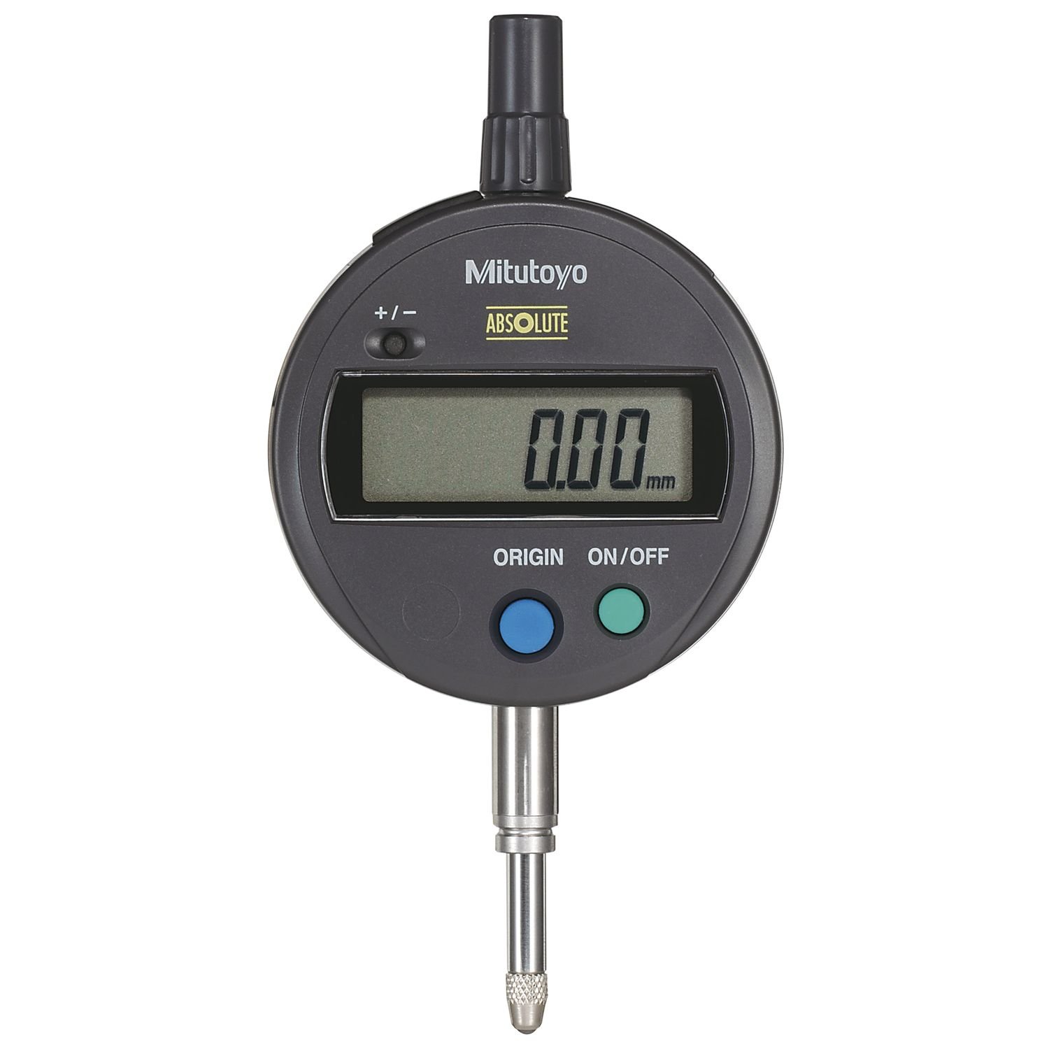
Figure 1: Mitutoyo 543-470B Absolute LCD Digimatic Indicator Id-C. This image shows the side profile of the digital indicator, highlighting its compact design, LCD display housing, and the measuring spindle.
2. Setup
2.1 Battery Installation
The indicator requires one SR44 battery (included). To install or replace the battery:
- Locate the battery compartment cover, typically on the back or side of the display unit.
- Carefully open the cover.
- Insert the SR44 battery with the correct polarity, usually indicated within the compartment.
- Securely close the battery compartment cover.
The battery life is approximately 5,000 hours under normal use.
2.2 Mounting the Indicator
The 543-470B indicator features an 8mm stem diameter and an M2.5 x 0.45 thread for mounting. It is designed with a flat back for secure attachment to various fixtures or stands.
- Ensure the mounting surface or fixture is clean and stable.
- Insert the 8mm stem into the appropriate mounting hole on your fixture.
- Secure the indicator using the clamping mechanism of your fixture. Ensure it is held firmly but do not overtighten to avoid damage.
- If using the M2.5 x 0.45 threaded back, attach it to a compatible threaded mount.
3. Operating Instructions
3.1 Power On/Off
Press the ON/OFF button to power the indicator on or off. Due to the absolute encoder, the indicator will display the spindle's absolute position upon power-on without needing to re-set the origin.
3.2 Origin-Set / Preset
The origin-set function establishes a reference point for measurement. The preset function allows setting a specific value at a given point.
- Origin-Set: Position the spindle at the desired zero reference point. Press the ORIGIN button to set this position as zero.
- Preset: Move the spindle to the desired preset position. Use the PRESET button and numerical input (if available) to enter a specific value for that position.
3.3 Zero-Set
The zero-set function temporarily sets the current spindle position to zero for incremental measurements, without affecting the absolute origin.
- Position the spindle at the desired temporary zero point.
- Press the ZERO/ABS button to set the display to zero. Subsequent measurements will be relative to this point.
- Press ZERO/ABS again to return to absolute measurement mode.
3.4 Go/No-Go Judgment
This function allows for quick verification of whether a measurement falls within specified tolerance limits.
- Set the upper and lower tolerance limits using the appropriate buttons (refer to the device's specific button layout for 'TOL' or 'LIMIT' settings).
- As measurements are taken, the display will indicate 'GO' (within limits) or 'NG' (outside limits) in full-size characters.
3.5 Counting Direction Switching
The indicator allows you to reverse the counting direction (positive/negative) based on the spindle's movement. This is useful for different measurement setups.
- Locate the DIR or +/- button.
- Press this button to toggle the counting direction.
3.6 Data Output
The indicator is equipped with SPC data output. Connect a compatible data cable (sold separately) to the data output port to transfer measurement data to a computer or data processor.
3.7 Inch/Millimeter Conversion
For inch/metric models, a dedicated button allows switching between metric (mm) and imperial (inch) units.
- Press the IN/MM button to toggle between measurement units.
4. Maintenance
4.1 Cleaning
The indicator has a dust/water protection level of IP42 or IP53 (dust-proof type). To maintain its performance:
- Wipe the display and body with a soft, dry cloth.
- For stubborn dirt, use a cloth lightly dampened with mild detergent, then wipe dry immediately.
- Do not use organic solvents (e.g., thinner, benzene) as they may damage the plastic components.
- Keep the measuring spindle clean and free of debris.
4.2 Battery Replacement
Replace the SR44 battery when the low voltage alarm appears on the display. Refer to Section 2.1 for battery installation instructions.
4.3 Storage
Store the indicator in a clean, dry environment, away from direct sunlight, extreme temperatures, and high humidity. If storing for an extended period, it is recommended to remove the battery.
5. Troubleshooting
This section addresses common issues and their potential solutions.
| Problem | Possible Cause | Solution |
|---|---|---|
| Display shows 'Low Voltage' alarm | Battery is low. | Replace the SR44 battery. |
| Display shows 'Counting Value Composition Error' or 'Over-flow Error' | Measurement range exceeded or internal calculation error. | Ensure measurements are within the 0-25.4mm range. Reset the indicator by powering off and on. If error persists, contact support. |
| Display shows 'Tolerance Limit Setting Error' | Incorrect tolerance limits set (e.g., upper limit less than lower limit). | Re-enter tolerance limits, ensuring they are logically correct. |
| No display or indicator does not power on | Dead battery or incorrect battery installation. | Check battery polarity and ensure it is properly seated. Replace battery if necessary. |
| Inaccurate readings | Dirty spindle, improper mounting, or environmental factors. | Clean the spindle. Ensure the indicator is securely mounted. Verify stable environmental conditions (temperature, vibration). Perform an origin-set. |
6. Specifications
| Specification | Detail |
|---|---|
| Model Number | 543-470B |
| Measurement Range | 0-25.4mm |
| Graduation | 0.001mm |
| Accuracy | +/-0.003mm |
| Display | LCD |
| Length Standard | Absolute electrostatic capacitance type linear encoder |
| Max. Response Speed | Unlimited |
| Stem Diameter | 8mm |
| Thread Type | M2.5 x 0.45 |
| Back Type | Flat Back |
| Battery Type | SR44 (1 pc.) |
| Battery Life | Approx. 5,000 hours (under normal use) |
| Dust/Water Protection Level | IP42 or IP53 (dust-proof type) |
| Material | Stainless Steel |
| Product Dimensions | 19.8 x 10.7 x 7.9 cm |
| Item Weight | 0.28 g |
7. Warranty and Support
For warranty information, technical support, or service inquiries regarding your Mitutoyo 543-470B Absolute LCD Digimatic Indicator Id-C, please contact Mitutoyo customer service or your authorized Mitutoyo dealer. Please have your model number (543-470B) and purchase details available when contacting support.
You can find contact information on the official Mitutoyo website or through your product documentation.


