
1. Product Overview
The Empire White Mountain Hearth VFSR30NAT is a 30-inch vent-free slope glaze burner designed for use with natural gas. This burner system incorporates ceramic beads to enhance flame appearance, creating a realistic fire effect. It features a Millivolt Safety Valve with an integrated on/off switch for user control and is remote-ready for convenience. The burner is capable of producing up to 38,000 BTU and requires an Empire "LS" log set of the same size for proper operation.
Key Features:
- Internal Ceramic Beads: Designed to tumble gas, creating a dynamic and realistic flame pattern.
- Millivolt Valve: Includes an on/off switch for direct control of the burner.
- Fuel Type: Operates on Natural Gas.
- Size: 30-inch burner, compatible with Empire "LS" log sets of matching size.
- Heat Output: Up to 38,000 British Thermal Units (BTU).

Figure 1: The Empire White Mountain Hearth VFSR30NAT 30-inch vent-free natural gas slope glaze burner shown with an Empire "LS" log set and active flames, illustrating its realistic fire appearance.
2. Safety Information
WARNING: Improper installation, adjustment, alteration, service, or maintenance can cause injury or property damage. Read the installation, operating, and maintenance instructions thoroughly before installing or servicing this equipment.
- This appliance is for use with Natural Gas only. Do not attempt to use with other fuel types.
- Vent-free gas appliances produce carbon monoxide. Ensure adequate ventilation and never operate in unventilated spaces.
- Always ensure proper clearances to combustible materials as specified in the full installation manual.
- Installation and service must be performed by a qualified installer, service agency, or gas supplier.
- Proposition 65 Warning: This product can expose you to chemicals including carbon monoxide, which is known to the State of California to cause birth defects or other reproductive harm. For more information go to www.P65Warnings.ca.gov.
- Do not place clothing or other flammable materials on or near the appliance.
- Keep children and pets away from the appliance when it is in operation.

Figure 2: This icon indicates that the burner is designed for Natural Gas fuel only. Verify your gas supply type before installation.
3. Package Contents
Upon unpacking, verify that all components are present and undamaged. If any parts are missing or damaged, do not attempt to install or operate the burner. Contact your dealer or the manufacturer immediately.
- VFSR30NAT 30-Inch Vent-Free Slope Glaze Burner Assembly
- Millivolt Safety Valve (pre-installed)
- Instruction Manual
- Mounting hardware (if applicable)
Note: Log sets are sold separately and are required for proper operation and aesthetic completion. Ensure you have an Empire "LS" log set of matching size (30-inch) for this burner.
4. Setup and Installation
Installation of this vent-free gas burner must comply with local codes, or in the absence of local codes, with the National Fuel Gas Code, ANSI Z223.1/NFPA 54. It is strongly recommended that installation be performed by a qualified professional.
4.1 Fireplace Requirements
This burner is designed for installation in a masonry or listed factory-built fireplace. Ensure your fireplace meets the minimum dimensions required for safe operation. Refer to the table below for non-Empire minimum firebox dimensions.
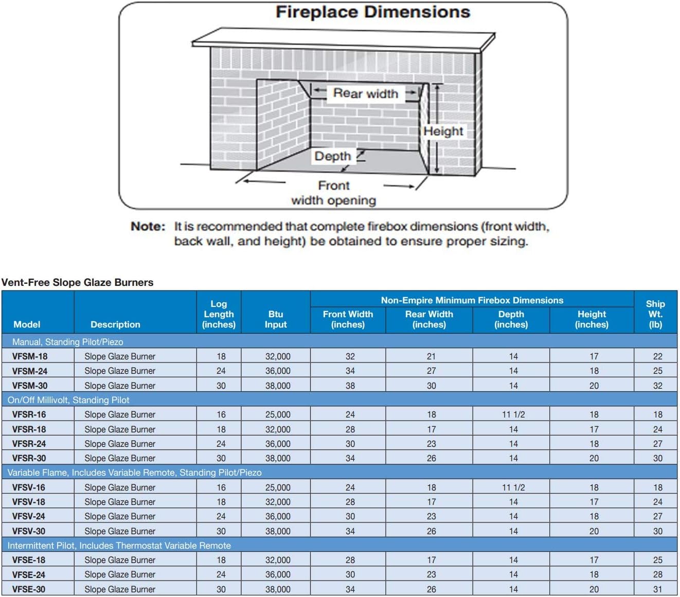
Figure 3: Diagram illustrating key fireplace dimensions (Front width opening, Rear width, Depth, Height) and a table detailing minimum non-Empire firebox dimensions for various Vent-Free Slope Glaze Burner models, including the VFSR-30.
4.2 Gas Connection
Connect the burner to your natural gas supply line. All gas connections must be leak-tested before operating the appliance. Use only approved gas piping and fittings.
4.3 Millivolt Wiring
The Millivolt Safety Valve system requires specific wiring for operation, including connections for the thermopile, thermocouple, and optional remote control or wall switch. Refer to the wiring diagram for correct connections.

Figure 4: Detailed wiring diagram for the Millivolt system, showing connections for the gas valve, thermopile, thermocouple, and optional remote control receiver or wall switch. Ensure all wiring is performed by a qualified technician.
4.4 Log Set Placement
Carefully place the Empire "LS" log set onto the burner according to the log set's specific instructions. Incorrect log placement can affect flame appearance and burner performance, and may lead to carbon monoxide production.
5. Operating Instructions
5.1 Lighting the Pilot
- Ensure the gas supply to the appliance is turned on.
- Locate the control knob on the Millivolt Safety Valve.
- Push the control knob in and turn it to the "PILOT" position.
- While holding the knob in, press the igniter button repeatedly until the pilot flame lights.
- Continue to hold the control knob in for approximately 60 seconds after the pilot lights to allow the thermocouple to heat up.
- Release the control knob. If the pilot extinguishes, repeat the lighting procedure.
- Once the pilot is lit, turn the control knob to the "ON" position.
5.2 Turning On the Main Burner
After the pilot is lit and the control knob is in the "ON" position:
- Manual Operation: Use the on/off switch located on the Millivolt Safety Valve to turn the main burner on or off.
- Remote Operation (Optional): If a remote control receiver is installed, use the remote control to activate the main burner. Refer to your remote control's instructions for pairing and operation.
5.3 Turning Off the Burner
- To turn off the main burner, use the on/off switch or remote control.
- To turn off the pilot, turn the control knob on the Millivolt Safety Valve to the "OFF" position.
- For extended periods of non-use, it is recommended to turn off the gas supply to the appliance.
6. Maintenance
Regular maintenance ensures safe and efficient operation of your burner. All maintenance should be performed by a qualified service technician.
- Annual Inspection: Have the burner and gas connections inspected annually by a qualified service technician. This includes checking for gas leaks, proper pilot and main burner operation, and condition of the ceramic beads and log set.
- Cleaning: Keep the burner area free from dust, lint, and debris. Use a soft brush or vacuum cleaner to gently clean the burner ports and pilot assembly. Do not use abrasive cleaners.
- Log Set: Inspect the log set periodically for cracks or deterioration. Replace any damaged logs to maintain proper flame pattern and safety.
- Ceramic Beads: Ensure the ceramic beads are properly positioned over the burner. If they become dislodged, carefully reposition them according to the original setup.
7. Troubleshooting
If you experience issues with your burner, consult the following common troubleshooting steps. For problems not listed or if issues persist, contact a qualified service technician.
| Problem | Possible Cause | Solution |
|---|---|---|
| Pilot will not light. | No gas supply; air in gas line; faulty igniter; pilot orifice clogged; thermocouple/thermopile issue. | Ensure gas supply is on. Bleed air from line. Check igniter spark. Clean pilot orifice. Inspect thermocouple/thermopile connections. |
| Pilot lights but will not stay lit. | Thermocouple not heating sufficiently; faulty thermocouple/thermopile; control knob not held long enough. | Hold control knob in for 60 seconds. Ensure pilot flame engulfs thermocouple. Replace faulty thermocouple/thermopile. |
| Main burner will not light. | Pilot not lit; control knob not in "ON" position; main burner orifice clogged; faulty Millivolt valve; remote control issue. | Light pilot. Turn control knob to "ON". Clean burner orifice. Check Millivolt valve. Check remote battery/pairing. |
| Poor flame appearance. | Incorrect log placement; burner ports clogged; low gas pressure. | Adjust log placement per log set instructions. Clean burner ports. Verify gas pressure with a qualified technician. |
8. Specifications
| Attribute | Detail |
|---|---|
| Model Name | White Mountain Hearth |
| Model Number | VFSR30NAT |
| Brand | Empire |
| Burner Size | 30-Inch |
| Fuel Type | Natural Gas |
| Ventilation Type | Vent-Free |
| Heat Output | 38,000 British Thermal Units (BTU) |
| Power Source | Gas Powered |
| Burner Type | Ceramic |
| Material | Ceramic |
| Product Dimensions (Approx.) | 17.5"D x 33"W x 9.25"H |
| Item Weight | 30 Pounds |
| Installation Type | Freestanding (within a fireplace) |
| Special Feature | Cordless (Millivolt system) |
| UPC | 720968265630 |
9. Warranty and Support
9.1 Warranty Information
This Empire White Mountain Hearth burner comes with a Limited Warranty. Specific terms and conditions of the warranty, including coverage duration and what is covered, are typically provided with the product packaging or can be obtained from the manufacturer. Please retain your proof of purchase for warranty claims.
9.2 Customer Support
For technical assistance, parts, or warranty inquiries, please contact Empire customer support. Refer to the contact information provided in your product packaging or visit the official Empire website for the most current support details.
When contacting support, please have your model number (VFSR30NAT) and proof of purchase readily available.


