
Intermatic FM1D20A-120
Grasslin by Intermatic FM1D20A-120 Electronic 24-Hour/7-Day Timer Module User Manual
Model: FM1D20A-120
1. Introduction
This manual provides detailed instructions for the installation, operation, maintenance, and troubleshooting of your Grasslin by Intermatic FM1D20A-120 Electronic 24-Hour/7-Day Timer Module. Please read this manual thoroughly before installation and operation to ensure safe and efficient use of the product. Keep this manual for future reference.
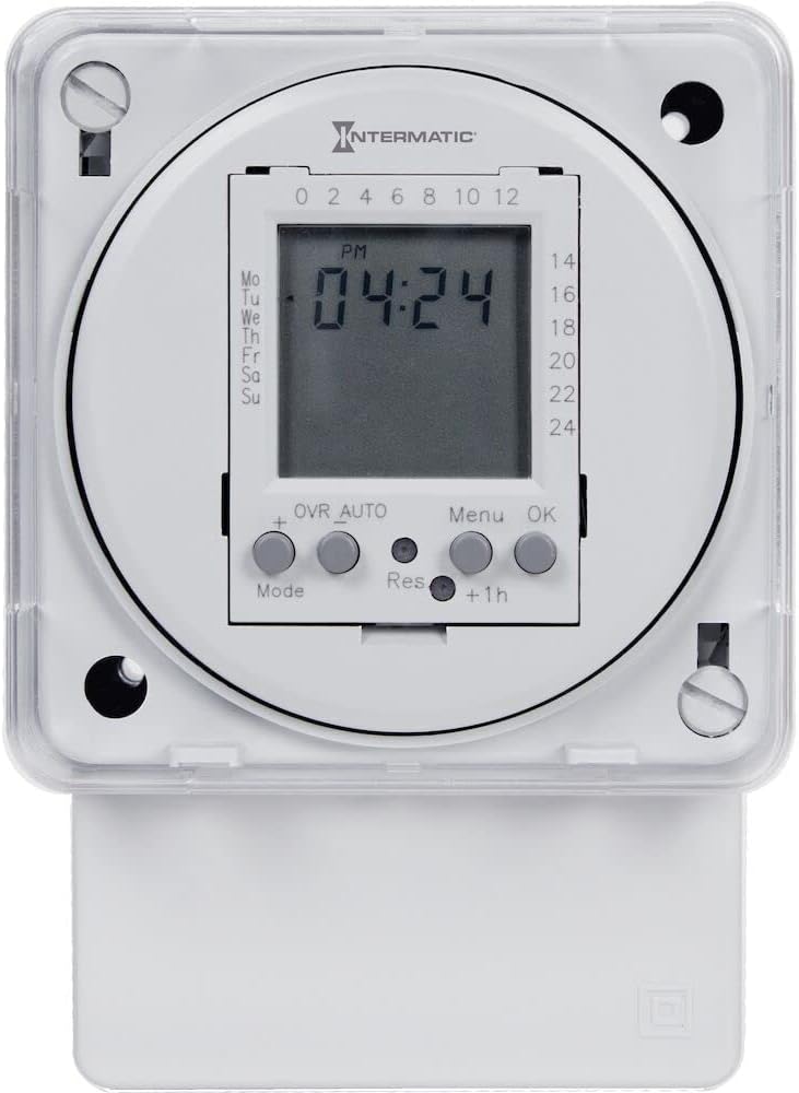
Figure 1.1: Front view of the Intermatic FM1D20A-120 Electronic 24-Hour/7-Day Timer Module, showing the digital display and control buttons.
2. Safety Information
Always observe the following safety precautions to reduce the risk of fire, electric shock, or injury to persons.
- WARNING: Risk of electric shock. Disconnect power at the circuit breaker or fuse before installing or servicing.
- Installation and wiring must be performed by a qualified electrician in accordance with all national and local electrical codes.
- Do not exceed the maximum electrical ratings of the device.
- Ensure all connections are secure and properly insulated.
- This device is intended for indoor use or within an appropriate outdoor enclosure.
3. Product Overview
3.1 Components
- Digital LCD Display: Shows current time, day, and programming status.
- Control Buttons: Mode, +, Res, Menu, OK, +1h for setting and programming.
- Terminal Connections: For power input and load output.
- Mounting Points: For surface or DIN rail installation.
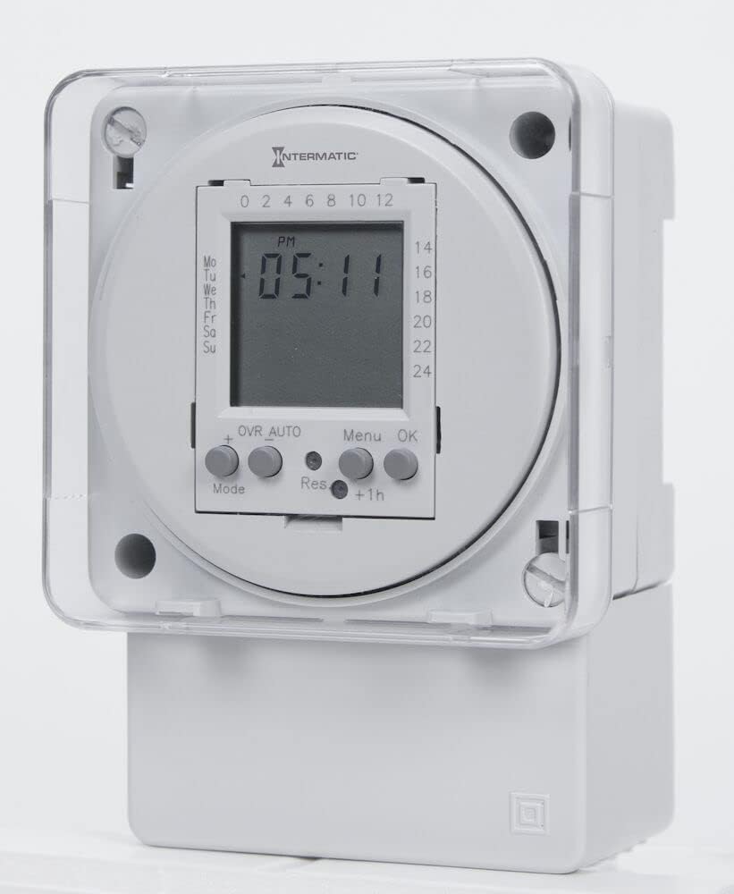
Figure 3.1: Detailed view of the timer's LCD display and the 'Mode', '+', 'Res', 'Menu', 'OK', and '+1h' control buttons.
3.2 Features
- 24-Hour/7-Day programmable timer.
- Up to 20 ON/OFF operations per day/week.
- Surface or DIN rail mountable for versatile installation.
- Compact design.
- Manual override function.
4. Setup and Installation
Before beginning installation, ensure power is disconnected at the main circuit breaker.
4.1 Mounting
- The FM1D20A-120 can be mounted on a standard DIN rail or surface-mounted using screws through the provided mounting holes.
- For surface mounting, mark and drill pilot holes, then secure the timer with appropriate screws.
- For DIN rail mounting, simply clip the timer onto the rail until it locks into place.
4.2 Wiring
Refer to the wiring diagram provided on the unit or in the separate wiring instructions. Ensure all connections are tight and correct for your application.
- Connect the incoming 120V AC power to the designated input terminals.
- Connect the load (device to be controlled) to the output terminals.
- Ensure proper grounding as per local electrical codes.

Figure 4.1: Side view of the timer module, illustrating the compact form factor and the location of the terminal connections for wiring.
4.3 Initial Power-Up
After wiring, restore power. The display should illuminate. If the display does not show, check power connections and circuit breaker.
5. Operating Instructions
5.1 Setting Current Time and Day
- Press the MODE button until the clock icon appears.
- Press MENU to enter time setting mode. The hour digits will flash.
- Use the + or - (if available, or repeated +) buttons to adjust the hour.
- Press OK to confirm and move to minutes. Adjust minutes similarly.
- Press OK to confirm and move to day of the week. Adjust day (Mo, Tu, We, etc.).
- Press OK to save and exit time setting.
5.2 Programming ON/OFF Cycles
The timer supports up to 20 ON/OFF programs.
- Press the MODE button until 'PROG' appears on the display.
- Press MENU to enter programming mode. '1 ON' will flash.
- Use + or - to set the desired ON time (hour and minute). Press OK after each.
- Select the days for this ON program (e.g., Mo-Fr, daily, individual days). Press OK.
- The display will now show '1 OFF'. Set the desired OFF time and days similarly.
- Repeat steps 3-5 for additional programs (2 ON/OFF, 3 ON/OFF, etc.).
- To exit programming, press MODE repeatedly until the clock display returns.
5.3 Manual Override
To manually switch the output state (ON/OFF) without affecting programmed cycles, press the OVR AUTO button. The display will show 'OVR' indicating manual override. Press again to return to 'AUTO' mode.
5.4 Resetting the Timer
To clear all settings and programs, locate the small 'Res' button (often recessed) and press it using a pointed object (e.g., a pen tip). The display will reset to default settings.
6. Maintenance
The FM1D20A-120 timer module requires minimal maintenance.
- Cleaning: Wipe the unit with a soft, dry cloth. Do not use abrasive cleaners or solvents.
- Connections: Periodically check electrical connections to ensure they remain secure.
- Backup Battery: The unit contains an internal, non-replaceable backup battery to retain programming during power outages. The lifespan of this battery can vary. If the timer consistently loses programming after short power interruptions, the battery may be nearing the end of its life, and the unit may need replacement.
7. Troubleshooting
| Issue | Possible Cause | Solution |
|---|---|---|
| Timer display is blank. | No power supply; incorrect wiring. | Check circuit breaker. Verify wiring connections are correct and secure. |
| Programs not executing. | Incorrect time/day setting; programming error; timer in manual override. | Verify current time and day. Re-check programmed ON/OFF times and days. Ensure timer is in 'AUTO' mode (not 'OVR'). |
| Timer loses settings after power outage. | Internal backup battery depleted. | The internal battery has a limited lifespan. If this occurs frequently, the unit may need to be replaced. |
| Display shows erratic characters. | Electrical interference; internal error. | Perform a full reset using the 'Res' button. If the issue persists, contact support. |
8. Specifications
| Specification | Detail |
|---|---|
| Model Number | FM1D20A-120 |
| Voltage | 120V AC |
| Frequency | 50/60 Hz |
| Maximum Operations | 20 ON/OFF cycles |
| Dimensions (D x W x H) | 2.06"D x 2.83"W x 4"H |
| Item Weight | 0.5 Pounds (approx. 8 ounces) |
| Mounting Type | Surface / DIN Rail |
| UPC | 078275121607 |
| Country of Origin | CHINA |
9. Warranty and Support
This product is covered by a manufacturer's warranty. Please refer to the manufacturer's official documentation or website for specific warranty terms and conditions.
For technical support, product inquiries, or warranty claims, please contact Intermatic customer service. Contact information can typically be found on the manufacturer's website or product packaging.
Related documentsFM1D20A-120


Ask a question about this manual
Ask about setup, troubleshooting, compatibility, parts, safety, or missing instructions. Manuals+ will review the question and use this page’s manual context to help answer it.