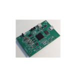
ANALOG DEVICES MAX96751 EVKIT Evaluation Board

Specifications
- Product Name: MAX96751 Evaluation Kit
- Compatibility: HDMI 2.0 Serializer EV Kit
- Forward Link Rates: 3Gbps or 6Gbps
- Power Options: 12V DC Supply (Included), USB, PoC, Externally Powered
- Interface: I2S Audio Interface Header for GPIO, I2C, UART, and SPI Signals
- Software Compatibility: Windows 10-Compatible Software
- Features: Configurable Power-Over-Coax (PoC), Line Fault Circuits, GMSL Channel Signal Integrity Tools
- Assembly: Fully Assembled and Tested PCB Layout
Procedure
The MAX96751 COAX/STQ EV kit comes fully assembled and tested.
Follow these steps to verify board operation:
- Step 1: Ensure all required equipment is available.
- Step 2: Connect the MAX96751 coax EV kit and MAX96752 coax EV kit as per the provided instructions.
- Step 3: Power up the system using the 12V DC supply or other power options.
- Step 4: Install the evaluation kit software on your computer using the provided installation files.
- Step 5: Use the graphical user interface program to interact with the evaluation kit.
- Step 6: Utilize the tools provided to characterize the GMSL channel signal integrity.
FAQ
Q: Can I use the MAX96751 Evaluation Kit without a Windows PC?
A: No, the evaluation kit software is compatible with Windows operating systems only.
Evaluates: MAX96751
General Description
The MAX96751 evaluation kit (EV Kit) provides a proven design to evaluate the MAX96751 high-bandwidth giga-bit multimedia serial-link (GMSL) serializer with spread spectrum and full-duplex control channel with the use of a standard FAKRA coaxial cable. The EV kit also includes Windows® 10 software to provide a simple graphical user interface (GUI) for exercising features of the device.
For complete GMSL evaluation, order the MAX96751 coax EV kit and a companion deserializer board (MAX96752 coax EV kit referenced in this document).
Note: In the following sections, serializer refers to MAX96751. Deserializer refers to MAX96752.
Note: This document applies to both coax and HSD-STQ evaluation kits, coax EV kit is referenced in this document.
Benefits and Features
HDMI 2.0 Serializer EV Kit to Drive GMSL-2 Serial Data Outputs (50Ω FAKRA Coax or 100Ω HSD-STQ Connectors)
3Gbps or 6Gbps Forward Link Rates for System and Power Flexibility
- Configurable Power-Over-Coax (PoC) and Line Fault Circuits
- I2S Audio Interface
- Header for GPIO, I2C, UART and SPI Signals
- Windows 10-Compatible Software
- Tools to Characterize GMSL Channel Signal Integrity
- 12V DC Supply (Included), USB, PoC or Externally Powered
- Proven PCB Layout
- Fully Assembled and Tested
 Ordering Information appears at end of data sheet.
Windows and Windows 10 are registered trademarks and registered service marks of Microsoft Corporation.
MAX96751 Evaluation Kit
Quick Start
Required Equipment
To get started evaluating there are a few installation and setup requirements. This procedure walks you through the necessary steps for basic bring-up of the deserial-izer EV kit. Figure 2 shows a typical application using an HDMI Serializer with the oLDI deserializer.
Note: In the following sections, software-related items are identified by bolding. Text in bold refers to items from the EV Kit software. Text in bold and underlined refers to items from the Windows operating system.
Required Equipment
- MAX96751 coax EV kit
- MAX96752 coax EV kit
- FAKRA Coax Cable
- HDMI source, such as laptop computer or HDMI signal generator
- oLDI Display and oLDI Adapter Board
- Windows 10 PC with a spare USB port
- 12V DC, 500mA power supply

Procedure
The MAX96751 COAX/STQ EV kit is shipped with the PCB fully assembled and tested. Follow the steps below to verify board operation:
- Download and install latest GMSL2 EV kit software from the MAX96751 Evaluation Kit product page.
- Verify that the on-board jumpers on the deserializer board are in their default positions (Figure 3) with SW1 off.
- Configure SW3 as shown in Figure 3 to set serializer address to 0x80, coax mode, and I2C control.
- Connect the FAKRA cable from the OUTA+ terminal on the serializer board to the INA+ terminal on the deserializer.
- Connect the +12V wall DC power supply into J1. See Figure 4 for power supply details.
- Turn SW1 on for both the serializer and deserializer EV kits.
- Verify that the blue power LED and red Teensy® LED are illuminated.
- Verify the lock LED on both serializer and deserial-izer EV kits light up, indicating that the link has been
successfully established. If the LOCK_LED is off
or ERRB LED is on the deserializer board, see the Troubleshooting section. Due to the default error conditions enabled on the serializer device versus the default hardware configuration of the serializer board, the ERRB LED will be illuminated upon powerup. - Connect the USB cable between the PC and J4 on the serializer EV kit. Start the GUI by selecting Start | Programs | Analog Devices Inc | GMSL-SerDesEV.
- When the GUI opens, it automatically searches for any active listener in both I2C and UART mode and identifies a valid GMSL product. Once the serializer and deserializer are identified, they are shown as tabs in the GUI.
- Read register 0x00 in both deserializer and serializer to ensure both devices are active.
- The basic bring-up is now complete. Refer to Help |User’s Manual for GUI operation, GMSL2 User’s Guide for configuration of this device and its available features, or ADI Applications for additional details and support.

Table 1. Jumper Description
| JUMPER | SIGNAL | DEFAULT POSITION | FUNCTION |
| JMP1 | VSUP | 12V | Select source of board power |
| VDDIO | VDDIO | 3.3V | Select between 1.8V and 3.3V |
| J2 | SCL_TX | SCL | I2C or UART connection to serializer |
| J5 | SDA_RX | SDA | I2C or UART connection to serializer |
| J10 | POCA | Open | Power-over-coax enable for PHY A |
| J11 | POCB | Open | Power-over-coax enable for PHY B |
| C63/C51 | SIOA+ | C63 (FAKRA/COAX) | Allows switching between FAKRA and HSD connector |
| C64/C70 | SIOB+ | C64 (FAKRA/COAX) | Allows switching between FAKRA and HSD connector |
| C47/C50 | SIOA- | C47 (AC Term) | Allows switching between AC termination and HSD connector |
| C49/C68 | SIOB- | C49 (AC Term) | Allows switching between AC termination and HSD connector |
| J6 | GPIO00 | N/A | Test Point |
| J6 | MS | N/A | Test Point |
| J6 | GPIO04 | N/A | Test Point |
| J6 | RO | N/A | Test Point |
| J6 | MOSI | N/A | Test Point |
| J6 | WS | N/A | Test Point |
| J6 | SD | N/A | Test Point |
| J6 | SCKOR_ADD1 | N/A | Test Point |
| J6 | CXTP | N/A | Test Point |
| J6 | LOCK | N/A | Test Point |
| J6 | SDA_RX | N/A | Test Point |
| J6 | GND | N/A | Test Point |
| J6 | GPIO01 | N/A | Test Point |
| J6 | RCLKEN | N/A | Test Point |
| J6 | SS1 | N/A | Test Point |
| J6 | MISO | N/A | Test Point |
| J6 | SCLK | N/A | Test Point |
| J6 | SCK | N/A | Test Point |
| J6 | SDOR_ADD0 | N/A | Test Point |
| J6 | WSOR_ADD2 | N/A | Test Point |
| J6 | I2CSEL | N/A | Test Point |
| J6 | ERRB | N/A | Test Point |
| J6 | SCL_TX | N/A | Test Point |
| J6 | GND | N/A | Test Point |
| JUMPER | SIGNAL | DEFAULT POSITION | FUNCTION |
| TP_USB_5V | USB 5V | N/A | Test Point |
| TPS_3V3 | 3.3V | N/A | Test Point |
| TP_CEC | CEC (HDMI) | N/A | Test Point |
| TP_HDMI_5V | HDMI 5V | N/A | Test Point |
| TP_1V | 1V | N/A | Test Point |
| TP_1V8 | 1.8V | N/A | Test Point |
| TP_3V3 | 3.3V | N/A | Test Point |
| PWDNB | Power Down (active low) | N/A | Test Point |
Table 2. Items Included in the Evaluation Kit Package
| ITEM DESCRIPTION | QTY |
| MAX96751 EV Kit | 1 |
| USB Cable | 1 |
| +12V Wall Supply | 1 |
Troubleshooting
If the MAX96751 EV Kit fails to power up or does not function properly, try the appropriate remedial actions below:
- Make sure the boards’ red power switches (SW1) are set to the ON position.
- Verify that the device is powered properly. Check to ensure that the voltages at all device pins are within their operating ranges.
- Check that all jumpers are correctly set. Refer to the default jumper settings table in the serializer and deserializer EV kit data sheets. Also, ensure that all jumpers are firmly attached. Replace loose or damaged jumpers if necessary.
- Check that the USB cable is properly seated in the USB port. The USB LED should be lit if connected to a PC, even if the board is powered down.
- Check that the serializer and deserializer GMSL generations match. Both devices should start in the same mode (GMSL2).
- Check that the COAX/STQ cable connection between serializer and deserializer is good–it clicks when plugged in fully.
- Check to see if the DUT has been inadvertently put into Teensy reset mode. The board’s TEENSY_RST button should only be pressed when firmware is being flashed to the DUT. If the button is pressed during normal operation, the device goes into Teensy reset mode. Power-cycle the board to resume normal operation with the current firmware.
- Check that the I2C/UART jumpers match the DUT communication mode (SCL/SDA for I2C, TX/RX for UART).
- Check that the AC coupling capacitors are populated correctly and routing the serial link to the correct connector for COAX or STQ mode. For coax boards, capacitors C63 and C46 (SIOA) and capacitors C64 and C49 (SIOB) should be populated. For HSD boards, capacitors C60 and C51 (SIOA), and capacitors C68 and C70 (SIOB) should be populated.(MAX96751 COAX/HSD EV kit boards are shipped with the correct capacitors installed.)
- Check if the LOCK LED is ON in the absence of a connection to the deserializer: If so, then the DUT is either not powered correctly or damaged.
- Check that the microcontroller firmware is active by observing the blinking red Teensy LED (DS6)
at power-up. If the LED is not blinking, refer to the available software documentation to reprogram the microcontroller. - Check that the PC is detecting the COM port when the micro-USB cable is connected. Use the Windows Device Manager to check COM port status.
- Power-cycle the board and reopen the GUI.
- Serializer board is faulty, try a new or different serializer board.
Detailed Description of Hardware
The power configuration of the EV kit hardware may be re-configured to allow external supply connections. Figure 4 shows the power connection options.

Component Suppliers
| SUPPLIER | PHONE | WEBSITE |
| Amphenol RF | 800-627-7100 | www.amphenolrf.com |
| Hong Kong X’tals Ltd. | 852-35112388 | www.hongkongcrystal.com |
| Murata Electronics North America, Inc. | 770-436-1300 | www.murata-northamerica.com |
| ON Semiconductor | 602-244-6600 | www.onsemi.com |
| Rosenberger Hochfrequenztechnik GmbH | 011-49-86 84-18-0 | www.rosenberger.de |
| TDK Corp. | 847-803-6100 | www.component.tdk.com |
Note: Indicate that you are using the MAX96751 when contacting these component suppliers.
Ordering Information
| PART | TYPE |
| MAX96751COAXEVKIT# | EV kit |
| MAX96751HSDEVKIT# | EV kit |
| MAX-GMSL-I2S-ADP# | I2S Audio Adapter |
#Defines RoHs Compliant
Note: The MAX96751 coax EV kits are
normally ordered with a companion deserializer board: – MAX96752 EV kit (MAX96752COAXEVKIT#)
MAX96751EV Kit Bill of Materials
| ITEM | REF_DES | DNI/DNP | QTY | MFG PART # | MANUFACTURER | VALUE | DESCRIPTION | COMMENTS |
| 1 | C1, 2 | – | 2 | EMK316BB7226ML | TAIYO YUDEN | 22UF | CAPACITOR; SMT (1206); CERAMIC CHIP; 22UF; 16V; TOL=20%; TG=-55 DEGC TO +125 DEGC; TC=X7R | |
| 2 | C6, C7 |
– |
2 |
C3216X5R1E476M160AC | TDK | 47UF | CAPACITOR; SMT (1206); CERAMIC CHIP; 47UF; 25V; TOL=20%; MODEL=C SERIES; TG=-55 DEGC TO +85 DEGC; TC=X5R ; | |
| 3 | C8, C9, C12-C14, C19- C25, C77 | – | 13 | GRT188R61C106KE13 | MURATA | 10UF | CAPACITOR; SMT (0603); CERAMIC CHIP; 10UF; 16V; TOL=10%; TG=-55 DEGC TO +85 DEGC; TC=X5R; AUTO | |
|
4 |
C10, C11, C17, C18, C26, C29-C32, C34-C41, C46, C47, C49, C52, C53, C56, C58, C59, C62-C64, C66, C67, C72-C74, C78 |
– |
34 |
CGA2B3X7R1H104K050BB;C1005X 7R1H104K050BB;GRM155R71H104 KE14;GCM155R71H104KE02;C1005 X7R1H104K050BE;UMK105B7104K V-FR;CGA2B3X7R1H104K050BE | TDK;TDK;MURATA;MURATA;TDK;TAIYO YUDEN;TDK |
0.1UF |
CAPACITOR; SMT (0402); CERAMIC CHIP; 0.1UF; 50V; TOL=10%; TG=-55 DEGC TO +125 DEGC; TC=X7R | |
| 5 | C15 | – | 1 | C1608X7R1V105K080AC;CGA3E1X 7R1V105K080AC | TDK;TDK | 1UF | CAPACITOR; SMT (0603); CERAMIC CHIP; 1UF; 35V; TOL=10%; TG=-55 DEGC TO +125 DEGC; TC=X7R | |
| 6 | C16, C28, C33 | – | 3 | GRM188Z71C225KE43 | MURATA | 2.2UF | CAPACITOR; SMT (0603); CERAMIC CHIP; 2.2UF; 16V; TOL=10%;
TG=-55 DEGC TO +125 DEGC; TC=X7R |
|
| 7 | C42, C48 | – | 2 | C0402C0G500-150JNP; GRM1555C1H150JA01 | VENKEL LTD.;MURATA | 15PF | CAPACITOR; SMT (0402); CERAMIC CHIP; 15PF; 50V; TOL=5%; TG=-55 DEGC TO +125 DEGC; TC=C0G | |
| 8 | C43-C45, C54, C55, C57, C60, C61, C65, C69 | – | 10 | GRM155R71H103JA88 | MURATA | 0.01UF | CAPACITOR; SMT (0402); CERAMIC CHIP; 0.01UF; 50V; TOL=5%; TG=-55 DEGC TO +125 DEGC; TC=X7R | |
| 9 | C71 | – | 1 | C0402C0G500- 470JNE;CC0402JRNPO9BN470;GR M1555C1H470JA01;CL05C470JB5N NN | VENKEL LTD.;YAGEO PHYCOMP;MURATA;SAMSUNG ELECTRONICS | 47PF |
CAPACITOR; SMT (0402); CERAMIC CHIP; 47PF; 50V; TOL=5%; MODEL=; TG=-55 DEGC TO +125 DEGC; TC=C0G |
|
| 10 | C75, C76 | – |
2 |
TMK212AB7475K;CGJ4J1X7R1E475 K125AC;C2012X7R1E475K125AB;C GA4J1X7R1E475K125AC;GRM21BZ
71E475KE15 |
TAIYO YUDEN;TDK;TDK;TDK;MURATA | .7UF | CAPACITOR; SMT (0805); CERAMIC CHIP; 4.7UF; 25V; TOL=10%; TG=-55 DEGC TO +125 DEGC; TC=X7R | |
| 11 | D1, D2 | – | 2 | ES1D | FAIRCHILD SEMICONDUCTOR | ES1D | DIODE; RECT; SMA (DO-214AC); PIV=200V; IF=1A | |
| 12 | D3 | – | 1 | DFLS140L | DIODES INCORPORATED | DFLS140L | DIODE; SCH; SMT (POWERDI-123); PIV=40V; IF=1A | |
| 13 | D4 | – | 1 | B360B-13-F | DIODES INCORPORATED | B360B-13-F | DIODE; SCH; SCHOTTKY BARRIER DIODE; SMB; PIV=60V; Io=3A;
-55 DEGC TO +125 DEGC |
|
| 14 | D5 | – | 1 | 1N4742A | FAIRCHILD SEMICONDUCTOR | 12V | DIODE, ZENER, DO-41, Pd=1W, Vz=12V@Iz=21mA | |
| 15 | DS3 | – | 1 | SMLE13BC8T | ROHM SEMICONDUCTOR | SMLE13BC8T | DIODE; LED; SML-E1 SERIES; BLUE; SMT (0603); VF=2.9V; IF=0.005A; | |
| 16 | DS4, DS6 | – | 2 | SML-P11UTT86 | ROHM | SML-P11UTT86 | DIODE; LED; SMT; PIV=1.8V; IF=0.02A | |
| 17 | DS5 | – | 1 | SML-P11MTT86 | ROHM | SML-P11MTT86 | DIODE; LED; SMT; PIV=5V; IF=0.02A | |
| 18 | EXT, GND | – | 2 | 9020 BUSS | WEICO WIRE | MAXIMPAD | EVK KIT PARTS; MAXIM PAD; WIRE; NATURAL; SOLID; WEICO WIRE; SOFT DRAWN BUS TYPE-S; 20AWG | |
| 19 | J1 | – | 1 | PJ-002AH | CUI INC. | PJ-002AH | CONNECTOR; MALE; THROUGH HOLE; DC POWER JACK;
RIGHT ANGLE; 3PINS |
|
| 20 | J2, J5, VDDIO | – | 3 | PCC03SAAN | SULLINS | PCC03SAAN | CONNECTOR; MALE; THROUGH HOLE; BREAKAWAY; STRAIGHT THROUGH; 3PINS; -65 DEGC TO +125 DEGC | |
|
21 |
J3 |
– |
1 |
393570002 |
MOLEX |
393570002 |
CONNECTOR; FEMALE; THROUGH HOLE; 0.3MM PITCH BEAU
EUROSTYLE FIXED MOUNT PCB TERMINAL BLOCK; RIGHT ANGLE; 2PINS |
|
| 22 | J4 | – | 1 | 1981568-1 | TE CONNECTIVITY | 1981568-1 | CONNECTOR; FEMALE; SMT; MICRO USB STANDARD TYPE B ASSY; RIGHT ANGLE; 5PINS | |
| 23 | J6 | – | 1 | PEC12DAAN | SULLINS ELECTRONICS CORP | PEC12DAAN | CONNECTOR; MALE; THROUGH HOLE; .1IN CC; BREAKAWAY
HEADER; STRAIGHT; 24PINS |
|
| 24 | J7 | – | 1 | PBC03SAAN | SULLINS | PBC03SAAN | CONNECTOR; MALE; THROUGH HOLE; BREAKAWAY; STRAIGHT; 3PINS; -65 DEGC TO +125 DEGC | |
| 25 | J8 | – | 1 | HDMR-19-01-S-SM | SAMTEC | HDMR-19-01-S-SM | CONNECTOR; FEMALE; SMT; HIGH SPEED I/O RECEPTACLE;
RIGHT ANGLE; 19PINS |
|
| 26 | J10, J11 | – | 2 | PCC02SAAN | SULLINS | PCC02SAAN | CONNECTOR; MALE; THROUGH HOLE; BREAKAWAY; STRAIGHT THROUGH; 2PINS; -65 DEGC TO +125 DEGC | |
| 27 | J12 | – | 1 | ERF8-010-05.0-S-DV-K | SAMTEC | ERF8-010-05.0-S-DV-K | CONNECTOR; FEMALE; SMT; RUGGED HIGH SPEED SOCKET;
STRAIGHT; 20PINS; |
|
| 28 | JAP, JBP | – | 2 | 59S2AQ-40MT5-Z_1 | ROSENBERGER | 59S2AQ-40MT5-Z_1 | CONNECTOR; MALE; THROUGH HOLE; FAKRA-HF RIGHT ANGLE PLUG PCB WITH HOUSING; RIGHT ANGLE; 5PINS | |
| 29 | JMP1 | – | 1 | PEC04SAAN | SULLINS ELECTRONICS CORP. | PEC04SAAN | CONNECTOR; MALE; THROUGH HOLE; BREAKAWAY;
STRAIGHT; 4PINS |
|
| 30 | L1, L6, L8-L10 | – | 5 | BLM18KG601SN1 | MURATA | 600 | INDUCTOR; SMT (0603); FERRITE-BEAD; 600; TOL=+/-25%; 1.3A | |
| 31 | L2 | – | 1 | DFE252012P-4R7M=P2 | MURATA | 4.7UH | INDUCTOR; SMT (2520); FERRITE CORE; 4.7UH; TOL=+/-20%; 1.7A | |
| 32 | L3, L4 | – | 2 | TFM201610ALMA2R2MTAA | TDK | 2.2UH | INDUCTOR; SMT (2016); THIN FILM; 2.2UH; TOL=+/-20%; 2.1A | |
| 33 | L5 | – | 1 | TFM252012ALMA-3R3MTAA | TDK | 3.3UH | EVKIT PART-INDUCTOR; SMT; ORIGINAL FINE COPPER; 3.3UH; TOL=+/-20%; 2.2A | |
| 34 | L7 | – | 1 | RFCMF1220100M3 | WALSIN TECHNOLOGY CORPORATION | RFCMF1220100M3 | INDUCTOR; SMT; CERAMIC CHIP; CHOKE; 0.3A | |
| 35 | L11 | – | 1 | BLM18SG121TN1 | MURATA | 120 | INDUCTOR; SMT (0603); FERRITE-BEAD; 120; TOL=+/-25%; 3A | |
| 36 | L12, L13 | – | 2 | LPS4040-154MR | COILCRAFT | 150UH | INDUCTOR; SMT; FERRITE; 150UH; 20%; 0.65A ; | |
| 37 | L14, L18 | – | 2 | 1210POC-223MR | COILCRAFT | 22UH | INDUCTOR; SMT; FERRITE; 22UH; 20%; 0.7A ; | |
| 38 | L15, L19 | – | 2 | PFL1005-561MR | COILCRAFT | 560NH | INDUCTOR; SMT (0402); SHIELDED; 560NH; 20%; 0.53A | |
| 39 | PWDNB |
– |
1 | 5000 | KEYSTONE | N/A | TEST POINT; PIN DIA=0.1IN; TOTAL LENGTH=0.3IN; BOARD HOLE=0.04IN; RED; PHOSPHOR BRONZE WIRE SILVER PLATE FINISH; | |
| 40 | R1-R3, R20-R23, R25, R26, R33, R43, R55-R59, R61-R66, R80, R81 |
– |
24 |
ERJ-2GEJ103 | PANASONIC | 10K | RESISTOR; 0402; 10K OHM; 5%; 200PPM; 0.10W; THICK FILM |
MAX96751EV Schematics


MAX96751 Evaluation Kit


Revision History
| REVISION NUMBER | REVISION DATE | DESCRIPTION | PAGES CHANGED |
| 0 | 11/23 | Initial release | — |
Information furnished by Analog Devices is believed to be accurate and reliable. However, no responsibility is assumed by Analog Devices for its use, nor for any infringements of patents or other rights of third parties that may result from its use. Specifications subject to change without notice. No license is granted by implication or otherwise under any patent or patent rights of Analog Devices. Trademarks and registered trademarks are the property of their respective owners.
Documents / Resources
 |
ANALOG DEVICES MAX96751 EVKIT Evaluation Board [pdf] User Guide MAX96751 EVKIT Evaluation Board, MAX96751, EVKIT Evaluation Board, Evaluation Board, Board |