![]()
IX-DV IX Series Networked Video Intercom System
Instruction Manual
IX Series
Networked Video Intercom System
IX-DV, IX-DVF, IX-DVF-P, IX-DVF-2RA, IX-DVF-RA, IX-DVF-L,
IX-SSA, IX-SSA-2RA, IX-SSA-RA
Introduction
- Read this manual before installation and connection. Read the “Setting Manual” and “Operation Manual”. The manuals can be downloaded from our homepage at “https://www.aiphone.net/support/software-document/” free of charge.
- After completing installation and connection, program the system according to the “Setting Manual”. The system cannot operate unless it is programmed.
- After performing installation, review with the customer how to operate the system. Leave documentation accompanying the Master Station with the customer.
 Perform installation and connection only after gaining a sufficient understanding of the system and this manual.
- The illustrations used in this manual may differ from the actual stations.
Literature information
The important information concerning the correct operation and what you should observe is marked with the following symbols.
 Warning Warning |
This symbol means that operating the device incorrectly or ignoring these precautions may cause severe injury or death. |
| Caution |
This symbol means that operating the device incorrectly or ignoring these precautions may cause severe injury or property damage. |
| This symbol is intended to alert the user to prohibited actions. | |
| This symbol is intended to alert the user to important instructions. |
Precautions
Warning
Negligence could result in death or serious injury.
 |
Do not disassemble or modify the station. This may result in fire or electrical shock. |
 |
Do not use with a power supply voltage above the specified voltage. This may result in fire or electrical shock. |
|
Do not install two power supplies in parallel to a single input. Fire or damage to the unit could result. |
|
Do not connect any terminal on the unit to the AC power line. Fire or electric shock could result. |
|
For power supply, use the Aiphone power supply model specified for use with the system. If the non-specified product is used, fire or malfunction could result. |
|
Do not, under any circumstances, open the station. Voltage within some internal components may cause electrical shock. |
|
The device is not designed to explosion-proof specifications. Do not install or use in an oxygen room or other such locations filled with volatile gases. It May cause fire or explosion. |
Caution
Negligence could result in injury to people or damage to property.
|
Do not install or connect the device with the power on. May cause electrical shock or malfunction. |
| Do not turn on the power without first checking to make sure the wiring is correct and there are no improperly terminated wires. This may result in fire or electrical shock. |
|
|
Do not put your ear close to the speaker when using the station. May cause harm to the ear if a sudden loud noise is emitted. |
General Precautions
- Install low-voltage lines at least 30cm (11″) away from high-voltage lines (AC100V, 200V), especially inverter air conditioner wiring. Failure to do so may result in interference or malfunction.
- When installing or using the station, give consideration to the privacy rights of subjects, as it is the responsibility of the system owner to post signs or warnings in accordance with local ordinances.
Notice
- If the station is used in areas where there are business-use wireless devices such as a transceiver or mobile phones, it may cause malfunction.
- If the device is installed close to a light dimmer, an inverter electrical appliance or the remote control unit of a hot-water system or floor-heating system, it may create interference and cause a malfunction.
- If the device is installed in an area with an extremely strong electrical field, such as in the vicinity of a broadcasting station, it may create interference and cause a malfunction.
- If warm air from inside the room enters the unit, the internal and external temperature differences may cause condensation on the camera. Plugging of cable holes and other gaps where warm air might enter is recommended for preventing condensation.
Precautions for mounting
- If installed in a place where the sound is easy to echo, it may be difficult to hear the conversation with echoed sounds.
- Installing the device in locations or positions such as the following may affect the clarity of the image:
– Where lights will be shining directly into the camera at night time
– Where the sky fills much of the background
– Where the background of the subject is white
– Where sunlight or other strong light sources will shine directly into the camera

- In 50Hz regions, if a strong fluorescent light shines directly into the camera, it may cause the image to flicker. Either shield the camera from the light or use an inverter fluorescent light.
- Installing the device in the following locations could cause malfunction:
– Locations near heating equipment Close to a heater, boiler, etc.
– Locations subject to liquid, iron filings, dust, oil, or chemicals
– Locations subject to moisture and humidity extremes Bathroom, basement, greenhouse, etc.
– Locations where the temperature is quite low Inside a cold storage warehouse, the front of a cooler, etc.
– Locations subject to steam or oil smoke Next to heating devices or cooking space, etc.
– Sulphurous environments
– Locations close to the sea or directly exposed to the sea breeze - If existing wiring is used, the device may not operate properly. In that case, it will be necessary to replace the wiring.
- Do not, under any circumstances, use an impact driver to fasten screws. Doing so may cause damage to the device.
Example of System Configuration

Part Names and Accessories
Part Names


Included accessories
- IX-DV

- IX-DVF, IX-DVF-P, IX-DVF-2RA, IX-DVF-RA, IX-DVF-L, IX-SSA, IX-SSA-2RA, IX-SSA-RA

Status Indicator
Refer to “Operation Manual” for additional indicators not listed.
![]() : Lit
: Lit
![]() : Off
: Off
| Status (Pattern) | Meaning | |
| Orange flashing | Normal flashing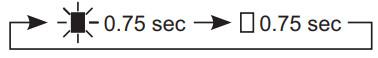 |
Booting |
Rapid flashing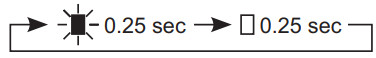 |
Device error | |
Long interval flashing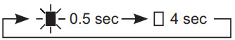 |
Communication failure | |
| Long irregular flashing |
Firmware version updating | |
Long irregular flashing |
Mounting micro SD card, unmounting micro SD card | |
| Long irregular flashing |
Initializing | |
| Blue light | Standby | |
How to Install
HID reader Installation (IX-DVF-P only)
* Use the short 6-32 × 1/4″ philips head screw (included with HID reader).

Video Door Station Installation
- IX-DV (surface mount)
• The installation height of the equipment should not exceed more than 2m (Upper Edge) from the ground level.

- IX-DVF, IX-DVF-P, IX-DVF-2RA, IX-DVF-RA, IX-DVF-L, IX-SSA, IX-SSA-2RA, IX-SSA-RA (flush mount)
• When installing the unit on a rough surface, please use sealant to seal the unit edges to prevent water from entering the unit. If the unit edges are left unsealed on a rough surface, an IP65 ingress protection rating is not guaranteed.

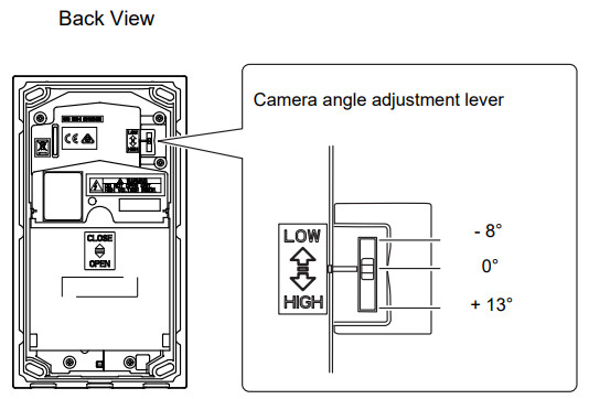
Camera View Area and Mounting Location (IX-DV, IX-DVF, IX-DVF-P, IX-DVF-2RA, IX-DVF-RA, IX-DVF-L)
- Camera view adjustment
Using the camera angle adjustment lever, the camera can be tilted up or down (-8°, 0°, +13°). Adjust the camera to the optimal position.
- Camera view range
The camera range as illustrated is only an approximate indication and may vary according to the environment.
IX-DV, IX-DVF IX-DVF-P, IX-DVF-2RA, IX-DVF-RA, IX-DVF-L
When light enters the camera, the monitor screen may flicker brightly or the subject may become dark. Try to prevent strong lighting from entering the camera directly.

How to Connect
Connection Precautions
● Cat-5e/6 cable
- For connection between devices, use a straight-through cable.
- If necessary, when bending the cable, please observe the manufacturer’s recommendations. Failure to do so could cause a communication failure.
- Do not strip away the cable insulation anymore than is necessary.
- Perform termination in accordance with TIA/EIA-568A or 568B.
- Before connecting the cable, be sure to verify conduction using a LAN checker or similar tool.
- An RJ45-covered connector cannot be connected to the LAN ports of the master stations or the door stations. Use cables without covers on the connectors.
- Be careful not to pull on the cable or subject it to excessive stress.
Precautions regarding low-voltage line
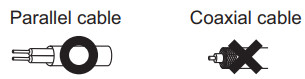
- Use PE (polyethylene)-insulated PVC jacketed cable. Parallel or jacketed conductors, mid-capacitance, and non-shielded cable are recommended.
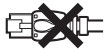
- Never use twisted-pair cable or coaxial cable.
- 2Pr quad V twisted pair cables cannot be used.
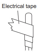
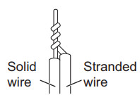
- When connecting low-voltage lines, perform the connection using either the crimp sleeve method or soldering, then insulate the connection with electrical tape.
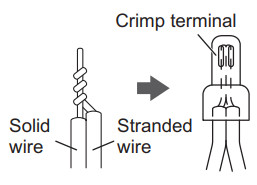
Crimp sleeve method
- Twist the stranded wire around the solid wire at least 3 times and crimp them together.
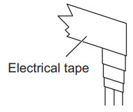
- Overlap the tape by at least a half-width and wrap the connection at least twice.
Soldering method
- Twist the stranded wire around the solid wire at least 3 times.
- After bending down the point, perform soldering, with care that no wires protrude from the soldering.
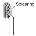
- Overlap the tape by at least a half-width and wrap the connection at least twice.
![]()
- If the connector-attached lead wire is too short, extend the lead with an intermediate connection.
- As the connector has a polarity, perform the connection correctly. If the polarity is incorrect, the device will not operate.
- When using the crimp sleeve method, if the end of the connector-attached lead wire has been soldered, first cut off the soldered part and then perform crimp.
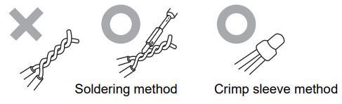
- After completing the connection of wires, check that there are no breaks or inadequate connections. When connecting low-voltage lines in particular, perform the connection using either soldering or the crimp sleeve method and then insulate the connection with electrical tape. For optimal performance, keep the number of wiring connections to a minimum.
Simply twisting low-voltage lines together will create poor contact or will lead to oxidization of the surface of the low voltage lines over long-term use, causing poor contact and resulting in the device malfunctioning or failure.
Wiring Connection
![]() • Insulate and secure unused low-voltage lines and the connector-attached lead wire.
• Insulate and secure unused low-voltage lines and the connector-attached lead wire.


*1 Contact Input Specifications
| Input method | Programmable dry contact (N/O or N/C) |
| Level detection method | |
| Detection time | 100 msec or more |
| Contact resistance | Make: 700 0 or less Break: 3 ka or more |
*2 Audio Output Specifications
| Output impedance | 600 Ω |
| Output audio level | 300 mVrms (with 600 Ω termination) |
*3 Relay Output Specifications
| Output method | Form C dry contact (N/O or N/C) |
| Contact rating | 24 VAC, 1 A (resistive load) 24 VDC, 1 A (resistive load) Minimum overload (AC/DC): 100mV, 0.1mA |
*4 The intercom unit can be powered by using a PoE switch or Aiphone PS-2420 power supply. In the case “PoE PSE” output of the intercom unit is used to power other devices, IEEE802.3at compatible PoE switch must be used to power the intercom unit.
In the case both a PoE switch and Aiphone PS-2420 power supply are used in combination to power the intercom unit, PS-2420 can provide backup power if the PoE power supply fails. this allows continuous recording functions etc. to continue operating.
![]()
https://www.aiphone.net/
AIPHONE CO., LTD., NAGOYA, JAPAN
Issue Date: Dec.2019 FK2452 Ⓓ P1219 BQ 62108
Documents / Resources
 |
AIPHONE IX-DV IX Series Networked Video Intercom System [pdf] Instruction Manual IX-DV, IX-DVF, IX-DVF-P, IX-DVF-2RA, IX-DV IX Series Networked Video Intercom System, IX-DV, IX Series, Networked Video Intercom System, IX-DVF-RA, IX-DVF-L, IX-SSA, IX-SSA-2RA, IX-SSA-RA |


