![]() PiPER Robotic Arm Quick Start
PiPER Robotic Arm Quick Start
User Manual
AgileX Robotics
PiPER ROBOTIC ARM
Quick start user manual V1.0
2024.09
Important Safety Informa8on
This chapter contains important safety information that must be read and understood by any user or organization before using the device for the first time. If there are any questions regarding the usage, please contact us at support@agilex.ai. It is essen(al to follow and implement all assembly instructions and guidelines in other chapters of this manual. Special a Qention should be paid to the text associated with warning signs.
Warning icon:![]() This refers to situations that may cause danger and, if not avoided, could result in personal injury or serious equipment damage.
This refers to situations that may cause danger and, if not avoided, could result in personal injury or serious equipment damage.
Warning ![]() :AgileX assumes no responsibility if the robotic arm is damaged, altered, or modified in any way. AgileX is not liable for any damages to the robotic arm or any other equipment caused by program errors or robotic arm malfunctions.
:AgileX assumes no responsibility if the robotic arm is damaged, altered, or modified in any way. AgileX is not liable for any damages to the robotic arm or any other equipment caused by program errors or robotic arm malfunctions.
Limita8on of Liability: Any safety information contained in this manual shall not be considered as a warranty of the AgileX robotic arm. Even if the robot arm complies with all safety instructions, it may still cause injury or damage.
The information in this manual does not include the design, installation and operation of a complete robotic arm application, nor does it include all peripheral equipment that may affect the safety of this complete system. The design and use of the complete system must comply with the safety requirements established in the standards and regulations of the country where the robot arm is installed.
It is the responsibility of the integrator and end customer of the robotic arm to ensure that relevant regulations and applicable laws and regulations are followed to ensure that there are no major hazards in the complete robotic arm application example.
This includes but is not limited to the following:
- Effectiveness and Responsibility
• Conduct a risk assessment for the complete robotic arm system.
• Connect additional safety devices for other machinery as defined in the risk assessment.
• Ensure the accurate design and installation of the entire robotic arm system, including both so ware and hardware.
• The integrator and end customer must follow relevant regulations and applicable legal requirements for safety assessment to ensure that the developed robotic arm has no major hazards or safety risks in actual applications.
• Be aware of any potential safety risks before operating and using the equipment.
• Ensure that users do not modify any safety measures.
• Collect all documents in the technical files, including the risk assessment and this manual. - Environment
• Before first use, carefully read this manual to understand basic operations and usage guidelines.
• Choose a relatively open area for use, as the robotic arm does not come with any automa(c obstacle-avoidance sensors.
• Use the robotic arm in an environment with a temperature between -20°C and 50°C.
• If the robotic arm is not custom-made with a specific IP protection rating, its water and dust resistance is rated at IP22. - Check
• Ensure the robotic arm has no visible abnormalities.
• Ensure proper connection of the wiring harness during use. - Operation
• Ensure the surrounding area is relatively open during operation.
• Operate within visual range.
• The maximum payload of the robotic arm is 1.5KG; ensure that the effective load does not exceed 1.5KG during use.
• If the equipment shows abnormalities, stop using it immediately to avoid secondary damage.
• If abnormalities occur, contact relevant technical personnel and do not handle it on your own.
• Use the equipment in an environment that meets the IP protection rating requirements. - Warnings
 :
:
• Ensure that the robotic arm and tools/end effectors are always correctly and securely fixed in place.
• If you must enter the robotic arm’s working space, wear safety goggles to protect yourself.
• Ensure that the robotic arm has enough space for free movement.
• Ensure that safety measures are established as defined in the risk assessment.
• Do not wear loose clothing while operating the robotic arm. Tie back long hair when operating the robotic arm.
• Do not use the robotic arm if it is damaged or showing any abnormalities.
• If the host computer so ware displays error messages, immediately perform an emergency stop and contact relevant technical personnel.
• Ensure that people keep their heads, faces, or other body parts away from the operating robotic arm or from the area the robotic arm can reach during operation.
• Never modify the robotic arm. Altering the robotic arm may introduce unforeseen dangers for the integrator.
• Do not expose the robotic arm to permanent magnetic fields. Strong magnetic fields can damage the robotic arm.
• The robotic arm generates heat during operation. Do not handle or touch the robotic arm while it is operating or shortly after it has stopped, as prolonged contact may cause discomfort. Power off the system and wait for one hour for the robotic arm to cool down.
• Connecting different machines together may increase risk or introduce new hazards. Always perform a comprehensive risk assessment for the entire installation. Depending on the risk assessment, different functional safety levels may apply; therefore, when different safety and emergency stop performance levels are required, always choose the highest performance level. Always read and understand the manuals for all devices used in the installation.
Introduction
This 6 DOFs robotic arm is specifically designed for the education and research industry, consumer-level applications, and industrial automation. With a payload capacity of 1.5kg, it is suitable for various research and industrial applications, including humanoid robots, automatic assembly, and automated handling. The six rotating joints provide full-range operational flexibility, ensuring high precision and repeatability. The robotic arm features a modular design, making it easy to maintain and upgrade. It offers an intuitive user interface that simplifies programming and operation, allowing even non-professionals to get started quickly. It can be widely applied in fields such as scientific research, education, automotive manufacturing, electronics assembly, food processing, laboratory automation, and medical equipment operation.
1.1. Packing List
| Name | Quantity |
| 6 DOFs Robotic arm | 1 |
| USB toCAN module | 1 |
| Power adapter | 1 |
| MicroUSB cable | 1 |
| Power and communication cable | 1 |
| Base mounting screws | 4 |
| Base installation wrench | 1 |
Basic Usage
The robotic arm has 6 DOFs and a 1.5kg payload at the end. The six rotating joints provide full-range operational flexibility, ensuring high precision and repeatability. It features a lightweight design, allowing the robotic arm to achieve fast motion capabilities while maintaining a relatively high payload capacity. It can be widely used in embodied intelligence for real-world data collection. 2.1. Electrical Interface Introduction
- Power and communication port
- Status indicator light
- J1J2 connection port
- Power positive
- Power negative
- CAN-H
- CAN-L
Note: Align the red dot with the corresponding red dot on the cable. The textured area of the connector is designed to retract under force. During installation, align the red dot downward with the protruding point and insert it directly. To remove, press down on the textured area and pull it out.
CAN Connection and Preparation
Lead out the CAN cable and connect the CAN_H and CAN_L wires to the CAN_TO_USB adapter.
Connect the CAN_TO_USB adapter to the laptop’s USB port. The connection diagram is shown in Figure 3.4.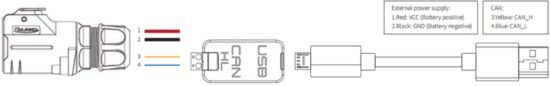
Note: If using a non-standard charger, the power input must not exceed 26V, and the current must be no less than 10A.
2.2. Robo8c Arm Teach/Demonstra8on Mode Instruc8ons
The robotic arm’s drag & teach mode status is indicated by the button light between J5 and J6.
There are three types of robo(c arm status light displays:
- No light display: Robotic arm’s drag & teach mode is stopped, or the drag recording has ended.

- Solid green light: The robotic arm has entered the drag & teach mode for trajectory recording.

- Flashing green light: The robotic arm has entered the drag & teach mode for trajectory playback.
How to switch to drag mode:
- Single click button: Toggle between drag teach trajectory recording and stopping the drag recording.
- Double click button: Activates the drag teach trajectory playback mode.
Instructions:
First, observe the indicator light status:
- If the light is off, click the button once. The green light should turn solid, indicating that the user can drag the robotic arm to start recording the trajectory.
- If the light is off and a trajectory has been recorded previously, double-click the button. The green light should flash every 500ms, indicating the robotic arm is in playback mode and will reproduce the recorded trajectory.
- If the light is solid, it indicates trajectory recording is in progress. To stop the recording, click the button once; the light should turn off, indicating that recording has ended. If you want to replay the trajectory, follow step 2.
- If the light is flashing, the robotic arm is currently in playback mode.
Notes:
- During trajectory playback, the user must keep a safe distance from the robotic arm to avoid injury.
- Each time the robotic arm enters teach trajectory recording mode, the previously recorded trajectory is erased. The playback mode will use the most recent recorded trajectory.
- The maximum trajectory recording time is 3 minutes; any trajectory exceeding this time will be invalid.
- After finishing drag teaching, ensure the indicator light is off/drag teaching mode is stopped.
- If you want to switch to host computer control or command control, ensure the indicator light is off/drag teach mode is stopped. Then switch to standby mode via the host computer, and after entering standby mode, switch to CAN mode. The same applies to command control—first switch to standby mode, then switch to CAN control mode.
2.3. Base Installation Instructions
The robotic arm base is installed using screws for fixation. The base has four pre-drilled MS threaded holes. The accessory kit includes four M5 screws, which can be tightened using the provided hex tool. The hole spacing is 7Omm. If you need to attach the base to mobile equipment or a fixed surface, you can design the corresponding structure with 7Omm hole spacing.
2.4. End Part Installation Instructions
The end can be equipped with other tools via a flange. Optional accessories include a two-finger gripper and a teach pendant. The installation method is shown in the diagram below. For detailed specifications of the two-finger gripper and teach pendant, refer to
Appendix 1: Optional End Tool Specifications.
ArmRobotUA Host Computer Usage Instructions
Software Download:
Link: https://pan.baidu.com/s/1EJf_6QqxdC7NzBqsBhjt2w?pwd=y8gg
Password: y8gg
Using a PC with Windows 7 or higher, double-click to open the host computer software. Through this human-machine interaction software, you can operate the robotic arm and read feedback data from the external network of the robotic arm. The user interface
is shown as follows: Host Computer Opera(on Interface
Names of the functional areas in the host computer software panel
| Index | Name |
| 1 | Robotic Arm Communication Button |
| 2 | Menu Options |
| 3 | Speed Percentage Setting |
| 4 | Robotic Arm Enable Button |
| S | Robotic Arm Emergency Stop Button |
| 6 | Window Resize/Close Buttons |
| 7 | Operation Function Area |
| 8 | 3D Simulation Model |
| 9 | Trajectory Library Function |
| 10 | Robotic Arm Joint Status |
| 11 | Robotic Arm Status Bar |
Secondary Development
Currently, the robotic arm supports secondary development through a Python SDK and ROS1 driver package. For detailed secondary development instructions, please refer to the GitHub link.
SDK:https://github.com/agilexrobotics/piper_sdk
ROS1:https://github.com/agilexrobotics/piper_ros
![]()
Documents / Resources
 |
AGILE X PiPER Lightweight Robotic Arm [pdf] User Manual PiPER Lightweight Robotic Arm, Lightweight Robotic Arm, Robotic Arm, Arm |