1. Introduction
This manual provides comprehensive instructions for the safe installation, optimal operation, and proper maintenance of your High-Power LED Projector Light Source Module. Designed for use in HD projectors and various DIY lighting applications, this module offers a powerful and efficient light source. Please read this manual thoroughly before installation and use to ensure correct setup and to maximize the lifespan and performance of the product.
2. Safety Information
WARNING: Improper handling or installation can lead to electric shock, fire, or damage to the product and connected equipment. Always follow these safety guidelines:
- Ensure all power is disconnected before installation or maintenance.
- This product operates at high voltage and temperature. Handle with care.
- Do not look directly into the LED light when it is operating, as it can cause eye damage.
- Ensure adequate heat dissipation. Overheating will significantly reduce the lifespan of the LED module.
- Only use with compatible power supplies that meet the specified voltage and current requirements.
- Keep out of reach of children.
- Do not modify the module. Any modifications will void the warranty and may create safety hazards.
3. Specifications
The following table details the technical specifications for the High-Power LED Projector Light Source Module (RD-806 Series). Note that specific configurations may vary.
| Feature | Specification |
|---|---|
| Product Name | High-Power LED Projector Light Source |
| Model Series | RD-806 Series (e.g., MT-CA4334-03, MT-CM3834-03, MT-CM3834-02) |
| Power Rate | 120W (typical for 10 series 7 parallel configuration) |
| Number of Chips | 70 chips (typical) |
| Light Flux | 120 lumens/Watt |
| Chip Usage | 35*35mil chip |
| Color Temperature | 8500K (White Light) |
| Operating Voltage | 32-36V (for 10 series configuration) |
| Support Frame | 4046 support |
| Encapsulation Glue | US Dow Corning |
| Estimated Lifespan | 40,000 hours (maintaining 80% brightness) |
| LED Chip Luminous Area | 17mm x 12mm (for 70-chip configuration) |
| Package Weight | 0.5 kg |
| Package Dimensions (L x W x H) | 10 cm x 10 cm x 10 cm |
Note: "Series" refers to the number of LEDs connected in series, and "Parallel" refers to the number of such series connected in parallel. For example, "10 series 7 parallel" means 10 LEDs in series, with 7 such strings connected in parallel.
4. Installation
Proper installation is crucial for the performance and longevity of your LED module. Please follow these steps carefully:
- Prepare the Mounting Surface: Ensure the surface where the LED module will be mounted is clean, flat, and capable of dissipating heat effectively. A heatsink is mandatory for high-power LEDs.
- Apply Thermal Paste/Pad: Apply a thin, even layer of high-quality thermal paste or attach a thermal pad to the back of the LED module or the heatsink. This ensures efficient heat transfer.
- Mount the LED Module: Securely attach the LED module to the heatsink using appropriate screws or clamps. Ensure firm contact between the module and the heatsink.
- Wiring Connections:
- Identify the positive (+) and negative (-) terminals on the LED module. These are typically marked on the module itself.
- Connect the positive (+) output from your constant current LED driver to the positive (+) terminal on the LED module.
- Connect the negative (-) output from your constant current LED driver to the negative (-) terminal on the LED module.
- Ensure all connections are secure and insulated to prevent short circuits.

Figure 1: LED module (MT-CA4334-03) showing positive (+) and negative (-) terminals for electrical connection. 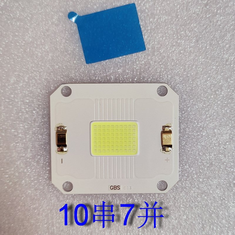
Figure 2: Another LED module variant (MT-CM3834-03) with R+ and R- terminals, also indicating polarity. - Power Supply Compatibility: Verify that your LED driver provides the correct voltage (32-36V for 10 series) and current for the specific configuration of your LED module (e.g., 10 series 7 parallel). Incorrect power supply can damage the LED.
- Test the Installation: Before final assembly, briefly power on the LED module to confirm it illuminates correctly. Observe for any flickering or unusual behavior.
Understanding LED Configurations:
- 10 Series 7 Parallel (10串7并): This configuration uses 70 chips, with 10 chips connected in series to form a string, and 7 such strings connected in parallel. This is a common configuration for 120W modules.
- 8 Series 12 Parallel (8串12): Another possible configuration, using 96 chips (8 chips in series, 12 strings in parallel). This would require a different operating voltage and current.
- Detailed Chip Information: The luminous area of the LED chip package is approximately 17mm x 12mm.


5. Operation
Once properly installed and connected to a compatible constant current LED driver, the module is ready for operation.
- Power On: Activate the power supply connected to the LED driver. The LED module should illuminate instantly.
- Monitoring: During operation, ensure the heatsink remains within acceptable temperature limits. Excessive heat can degrade performance and shorten lifespan.
- Light Output: The module provides a high-intensity white light (8500K). Avoid direct eye exposure.
6. Maintenance
Minimal maintenance is required for this LED module, but adhering to these guidelines will help ensure its longevity:
- Cleaning: Periodically, gently clean the surface of the LED module and heatsink to remove dust and debris. Use a soft, dry cloth. For stubborn dirt, a slightly damp cloth can be used, ensuring no moisture enters the electrical connections. Always disconnect power before cleaning.
- Thermal Management: Regularly check that the heatsink is free from obstructions and that airflow (if applicable, e.g., with a fan) is not impeded.
- Connection Check: Occasionally inspect wiring connections for any signs of wear, corrosion, or loosening.
7. Troubleshooting
| Problem | Possible Cause | Solution |
|---|---|---|
| LED does not light up | No power; incorrect wiring; faulty LED driver; damaged LED module. | Check power supply. Verify positive/negative wiring. Test LED driver. Replace LED module if damaged. |
| LED flickers or dims | Unstable power supply; incorrect current/voltage from driver; poor connection; overheating. | Ensure stable power. Verify driver output matches LED specs. Check all connections. Improve heat dissipation. |
| LED overheats quickly | Insufficient heatsink; poor thermal paste application; inadequate airflow. | Ensure heatsink is adequately sized. Reapply thermal paste. Improve ventilation around the heatsink. |
| Reduced brightness over time | Normal aging; prolonged overheating; operating outside specified parameters. | Ensure proper thermal management. Verify operating parameters. Consider replacement if lifespan is exceeded. |
8. User Tips
- Compatibility Check: Before purchasing or installing, always verify the specific part number and electrical specifications (voltage, current, series/parallel configuration) of your existing projector's light source to ensure compatibility with this LED module. For example, if replacing a "MT-CM6040-01" in a "Jifar T6" projector, confirm the voltage and wattage requirements.
- Power Supply Matching: Ensure your LED driver's output voltage and current precisely match the requirements of the LED module's configuration (e.g., 12 series 24 parallel will have different voltage/wattage needs than 10 series 7 parallel).
- Thermal Management is Key: High-power LEDs generate significant heat. A robust heatsink and, if necessary, active cooling (fan) are essential to prevent premature failure and maintain brightness.
9. Warranty and Support
For any technical assistance, troubleshooting beyond this manual, or warranty inquiries, please contact your point of purchase or the manufacturer's customer support. Keep your purchase receipt as proof of purchase.


