1. Introduction
This instruction manual provides detailed information on the installation, setup, and operation of your QIACHIP KR2202-4 2-channel RF Remote Control Switch and Universal RF Relay Receiver. This versatile device is designed to control various electrical appliances and systems, such as lighting, electric doors, automated curtains, and garage door openers, using a 433 MHz RF remote control.

Figure 1: QIACHIP KR2202-4 Receiver and Remote Controls
2. Specifications
Below are the technical specifications for the KR2202-4 receiver:
| Attribute | Value |
|---|---|
| Model Number | KR2202-4 |
| Input Voltage | AC 85V-220V |
| Working Current | 10A |
| Maximum Load Power | 1100W x 2 |
| Frequency | 433 MHz / 433.92MHz |
| Support Encoding Format | EV1527 (Learning Code) |
| Wiring Method | NC COM NO |
| Working Modes | Momentary, Toggle, Latching Time delay |
| Standby Current | 8.5mA |
| Receiver Sensitivity | -108dBM |
| Working Environment Temperature | -15°C to +75°C |
| Dimensions (L*W*H) | 68*48*18 mm |
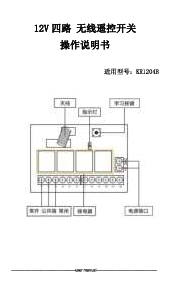
3. Components Overview
Familiarize yourself with the main components of the receiver board:

Figure 2: KR2202-4 Receiver Board Components
- Antenna: For receiving RF signals from the remote control.
- Indicator Light (LED2): Provides visual feedback during setup and operation.
- Learning Button: Used for pairing remote controls and setting working modes.
- NC (Normally Closed): Terminal 1 and 4.
- NO (Normally Open): Terminal 3 and 6.
- COM (Common/Public Port): Terminal 2 and 5.
4. Installation and Wiring
WARNING: Ensure power is disconnected before performing any wiring to prevent electric shock.
The receiver supports various wiring configurations depending on the type of device you wish to control. Always ensure correct polarity and voltage matching.
4.1. AC Motor Wiring Diagram

Figure 3: AC Motor Wiring Diagram (AC 85V-250V)
Note: Do not install or wire with electricity connected.
4.2. DC Motor Wiring Diagram

Figure 4: DC Motor Wiring Diagram (DC 12V 24V 36V...)
4.3. AC Device Wiring Diagram

Figure 5: AC Device Wiring Diagram (AC 85V-250V)
4.4. DC Device Wiring Diagram

Figure 6: DC Device Wiring Diagram (DC 1V-250V)
4.5. Additional Wiring Diagrams
-

Figure 7: Wiring Diagram for Lamps (AC85V-220V)
-

Figure 8: Three-Wire Motor Forward and Reverse Wiring Diagram
-

Figure 9: External Power Supply Motor Forward and Reverse Wiring Diagram
-

Figure 10: Output Switch Wiring Diagram
-

Figure 11: DC Motor Forward and Reverse Wiring Diagram
-

Figure 12: External Power Control Light Wiring Diagram
5. Operating Modes
The receiver supports three main working modes:
-
Momentary Mode:
When you press and hold the remote button, the relay connects (device turns ON). When you release the remote button, the relay disconnects (device turns OFF).
-
Toggle Mode:
Press the remote button once, and the relay connects (device turns ON). Press the same remote button again, and the relay disconnects (device turns OFF).
-
Latching Mode:
Press remote button A, and the relay connects (device turns ON). Press remote button B, and the relay disconnects (device turns OFF). This mode requires two distinct buttons on the remote for ON/OFF functionality.
6. Setup and Pairing
This section guides you through pairing your remote controls and setting the desired operating mode.
6.1. Demonstration Video
Video 1: Remote Control Pairing and Mode Demonstration
6.2. Clearing the Code (Reset)
To clear all previously matched remotes from the receiver's memory:
- Press the receiver's learning button 8 times.
- The receiver will clear all remote control data in its memory.
- When LED2 on the receiver flashes, the reset function is complete. All remote controls will no longer operate the receiver until re-paired.
6.3. Setting Momentary Mode
- Press the receiver's learning button once.
- Wait for the LED indicator on the receiver to turn off, indicating it has entered the learning state.
- Press a button on your remote control (e.g., button A). The LED indicator on the receiver board will flash and then turn off.
- After 3 seconds, the LED indicator will turn on again, confirming successful pairing in Momentary Mode.
6.4. Setting Toggle Mode
- Press the receiver's learning button twice.
- Wait for the LED indicator on the receiver to turn off, indicating it has entered the learning state.
- Press a button on your remote control (e.g., button A). The LED indicator on the receiver board will flash and then turn off.
- After 3 seconds, the LED indicator will turn on again, confirming successful pairing in Toggle Mode.
6.5. Setting Latching Mode
Note: For Latching Mode, you need to pair two different buttons on your remote control: one for ON and one for OFF.
- Press the receiver's learning button three times.
- Wait for the LED indicator on the receiver to turn off, indicating it has entered the learning state.
- Press the first button on your remote control (e.g., button A for ON). The LED will flash 5 times.
- Press the second button on your remote control (e.g., button B for OFF). The LED will flash 5 times.
- After 3 seconds, the LED indicator will turn on again, confirming successful pairing in Latching Mode (Button A = ON, Button B = OFF).
7. Maintenance
- Keep the receiver and remote controls dry. Moisture can damage electronic components.
- Avoid exposing the devices to extreme temperatures.
- Clean the devices with a soft, dry cloth. Do not use harsh chemicals or solvents.
- Ensure the antenna is not obstructed for optimal signal reception.
8. Troubleshooting
- Remote control not working: If a remote control stops working, try clearing all codes and re-pairing it according to the instructions in Section 6.2 and 6.3/6.4/6.5.
- New remote not pairing: The system can store a maximum of 25 remote controls. If you try to pair more than 25, the oldest paired remote will be overwritten. If you encounter issues, clear all existing codes and then pair your desired remotes.
- Intermittent operation: Check for potential sources of RF interference or ensure the remote control is within the effective range of the receiver.
9. User Tips
- The device communicates via RF wireless technology, offering reliable control.
- It is designed to be universal and can control various objects, making it highly adaptable for different home automation needs.
- Key features include momentary, toggle, and latching time delay working modes, providing flexibility for different applications. The product also holds CE certification.
- This device does not support connecting to a smartphone through an app.
- Common uses include automating curtains, controlling electric doors, and managing lighting systems.
10. Warranty and Support
For more detailed information, including comprehensive wiring diagrams, advanced troubleshooting, and warranty details, please refer to the official user manual PDF:
If you encounter any issues or require further assistance, please contact QIACHIP customer support.