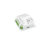
zeta ZAIO-MI Fyreye MkII Addressable Input Module
INSTALLATION MANUAL
General
The Fyreye MkII Addressable Input/Output Module is supplied with a backbox for surface mounting.
NOTE: The Input/Output Module is designed for indoor use only.
This product is loop powered and a maximum of 60 devices are allowed on any Zeta detection loop.
Model No: ZAIO-MI
Fyreye MkII Addressable Input/Output Module With Isolator
Surface Mounting
1. Mount the backbox as required and install all cables for termination.
2. Set the address of the unit as shown on page 3.
3. Terminate all cables.
4. Gently push the completed assembly towards the back box until the mounting holes are aligned and secure with the two mounting screws provided.
DO NOT OVERTIGHTEN.
Isolator Module
The ZAIO-MI Module is fitted with a bi-directional short-circuit isolator and will be unaffected by loop short-circuits on either loop input or output.
LED Indications
| Status | LED Indication | ||||||||||||||||||||||||||||||||||||||
| Switch closed | Illuminated red when monitored field contact is activated | ||||||||||||||||||||||||||||||||||||||
| Relay on | Illuminated red when relay is energized | ||||||||||||||||||||||||||||||||||||||
| Fault | Illuminated yellow when the input is open or short circuit | ||||||||||||||||||||||||||||||||||||||
| Polling | Flashed green when the device is polled by control panel | ||||||||||||||||||||||||||||||||||||||
| Isolating | Illuminated yellow when the loop is short or wrong connection circuit | ||||||||||||||||||||||||||||||||||||||
Wiring details
All wiring terminals will accept solid or stranded cables up to 2.5mm2
Interface to 3rd Party Panel


Technical Specification
| Model | ZAIO-MI | ||||||||||||||||||||||||||||||||||||||
| Part Number | 48-108 | ||||||||||||||||||||||||||||||||||||||
| Operating Voltage | 17-28V DC | ||||||||||||||||||||||||||||||||||||||
| Quiescent Current @ 24V | 1.0mA | ||||||||||||||||||||||||||||||||||||||
| Switch Input Closed (LED OFF) | 1.25mA | ||||||||||||||||||||||||||||||||||||||
| Relay Operated (LED ON) | 2.0mA (Max 2 LEDs on) | ||||||||||||||||||||||||||||||||||||||
| Relay Rating | SELV @ 1A | ||||||||||||||||||||||||||||||||||||||
| Isolating Current | 7.3mA | ||||||||||||||||||||||||||||||||||||||
| Input End Of Line | 20k | ||||||||||||||||||||||||||||||||||||||
| Alarm Triggering Resistor | 1k | ||||||||||||||||||||||||||||||||||||||
| Operating Temperature | -10°C to +55°C | ||||||||||||||||||||||||||||||||||||||
| Max Humidity | 95% RH Non Condensing | ||||||||||||||||||||||||||||||||||||||
| IP rating | IP21C | ||||||||||||||||||||||||||||||||||||||
| Size (mm) | 150 x 90 x 45 | ||||||||||||||||||||||||||||||||||||||
| Weight | 220g | ||||||||||||||||||||||||||||||||||||||
For information on the short circuit isolator operation see document GLT-224-6-9 available from your distributor.
Address Setting
The address of the Input/Output Module is set using the eight segments of the DIL switch. Each segment of the switch must be set to “0”(ON) or “1”(OFF), using a small screwdriver or similar tool. A complete list of address settings is shown overleaf. The maximum address is 250.


Alternative Soft Addressing Option
Using our hand held MkII programmer (Part No: 48-004), the unit can be addressed electronically.
Step 1: Set all addresses to zero 0000000
Step 2: Connect leads to LOOP IN+ and LOOP IN- as shown below

Step 3: Follow the procedure as described in the handheld programmer manual.
NOTE: When a device is soft addressed as above, the address CANNOT BE CHANGED by mechanical setting of the dip-switch. In order to re-enable the dip-switch the unit needs
to be set electronically back to zero first.
Isolator Function
The Isolator Function can be enabled or disabled according to the wiring method.
A. Enabling the Isolator Function

B. By-passing the Isolator Function

Functional Test Data
| Command Bit | Function | Input Bit | Function | ||||||||||||||||||||||||||||||||||||
| 3 | Not Used | 3 | Not Used | ||||||||||||||||||||||||||||||||||||
| 2 | ENABLE SWITCH CLOSED LED 0 = Normal 1 = Illuminated Switch Closed LED |
2 | Not Used | ||||||||||||||||||||||||||||||||||||
| 1 | Not Used | 1 | OPTO INPUT 0 = No Input 1 = Voltage On Input |
||||||||||||||||||||||||||||||||||||
| 0 | OPERATES RELAY 0 = Relay On 1 = Relay Off |
0 | MONITORED INPUT 0 = Quiescent 1 = Input Received |
||||||||||||||||||||||||||||||||||||
Input Condition and Status
| Status | Load Input | Analogue | LED State | Input Bit. Bit 0 | |||||||||||||||||||||||||||||||||||
| Short-circuit fault | <100Ω | 8 | Fault LED | =0 | |||||||||||||||||||||||||||||||||||
| Indeterminate | 100Ω-200Ω | 8 or 72 | / | =0 or 1 | |||||||||||||||||||||||||||||||||||
| Switch closed | 200Ω-11kΩ | 136 | Switch Closed | =1 | |||||||||||||||||||||||||||||||||||
| Indeterminate | 11kΩ-15kΩ | 136 or 72 | / | =0 or 1 | |||||||||||||||||||||||||||||||||||
| Normal (Switch open) | 15kΩ-25kΩ | 72 | – | 0 | |||||||||||||||||||||||||||||||||||
| Indeterminate | 25kΩ-30kΩ | 8 or 72 | / | 0 | |||||||||||||||||||||||||||||||||||
| Open-circuit fault | >30kΩ | 8 | Fault LED | 0 | |||||||||||||||||||||||||||||||||||
Analogue Return Back
| Voltage Input | Analogue Value | LED State | Input Bit.Bit1 | ||||||||||||||||||||||||||||||||||||
| <1V | Irrelevant | Irrelevant | =0 | ||||||||||||||||||||||||||||||||||||
| 1V-4V | Irrelevant | Irrelevant | =0/1 | ||||||||||||||||||||||||||||||||||||
| 4V-35V | Irrelevant | Irrelevant | =1 | ||||||||||||||||||||||||||||||||||||
| >35V(not allowed) | Irrelevant | Irrelevant | / | ||||||||||||||||||||||||||||||||||||
Troubleshooting
Before investigating individual units for faults, it is very important to check that the system wiring is fault free. Many fault conditions are the result of simple wiring errors. Check all connections to the unit and make sure that the correct value resistors are fitted where necessary.
Faultfinding
| Problem | Possible Cause | ||||||||||||||||||||||||||||||||||||||
| No response or missing | Incorrect address setting Incorrect loop wiring | ||||||||||||||||||||||||||||||||||||||
| Fault condition reported | Incorrect input wiring | ||||||||||||||||||||||||||||||||||||||
| Relay fails to operate | Control panel has incorrect cause and effect programming Incorrect address setting |
||||||||||||||||||||||||||||||||||||||
| Relay energized continuously | Incorrect loop wiring Incorrect address setting |
||||||||||||||||||||||||||||||||||||||
| Analogue value unstable | Dual address Loop data fault, data corruption |
||||||||||||||||||||||||||||||||||||||
| Constant alarm | Incorrect wiring Incorrect end-of-line resistor fitted Incompatible control panel software |
||||||||||||||||||||||||||||||||||||||
| CE | ||||||||||||||||||||||||||||||||||
| Zeta Alarms Limited, 72-78 Morfa Road, Swansea SA1 2EN 14 GLT-233-DoP-1 |
||||||||||||||||||||||||||||||||||
| EN54-18: 2005 EN54-17: 2005 Fire detection and fire alarm systems – Input/Output Devices Fire detection and fire alarm systems – Short Circuit Isolators Zeta Addressable Input Output Module with Isolator ZAIO-MI Intended for use in fire detection and fire alarm systems in and around buildings Response delay (response time) – PASS Performance under fire conditions – PASS Operational reliability – PASS Durability of operational reliability: temperature resistance – PASS Durability of operational reliability; vibration resistance – PASS Durability of operational reliability; humidity resistance – PASS Durability of operational reliability; corrosion resistance – PASS Durability of operational reliability; electrical stability – PASS |
Specifications
- Model: ZAIO-MI
- Operating Voltage: 24V
- Quiescent Current: Varies
- Switch Input Closed (LED OFF): Illuminated red when monitored field contact is activated
- Relay Operated (LED ON): Illuminated red when relay is energized
- Relay Rating: Varies
- Isolating Current: Varies
- Operating Temperature: Varies
- Max Humidity: Varies
- IP Rating: Varies
- Size (mm): Varies
- Weight: Varies
FAQ
Q: Can the Input/Output Module be used outdoors?
A: No, the Input/Output Module is designed for indoor use only.
Q: What is the maximum number of devices allowed on the Zeta detection loop?
A: A maximum of 60 devices are allowed on any Zeta detection loop.
Documents / Resources
 |
zeta ZAIO-MI Fyreye MkII Addressable Input Module [pdf] Installation Guide ZAIO-MI Fyreye MkII Addressable Input Module, ZAIO-MI, Fyreye MkII Addressable Input Module, MkII Addressable Input Module, Addressable Input Module, Input Module |


