WONDOM ASCM-A2D Audio ADC Module
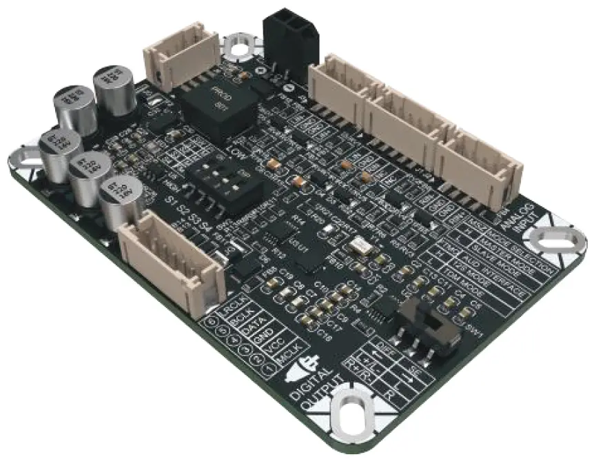
The ASCM-A2D is an audio analog-to-digital module that is designed to enable the sampling two analog channels simultaneously. ASCM-A2D also supports single-ended and differential signals.
Features
- 2-channel analog line that supports simultaneous sampling.
- Support single-ended and differential line-in(s).
- Support master and slave mode selection for the audio bus interface operation.
- Operating temperature between -20°C and 65°C.
Specification(s)
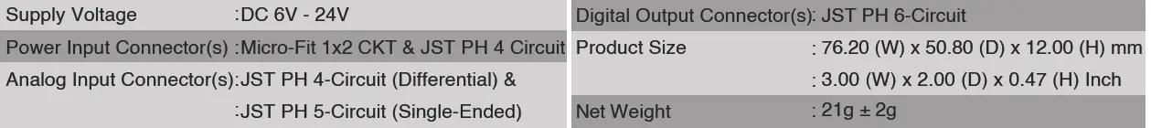
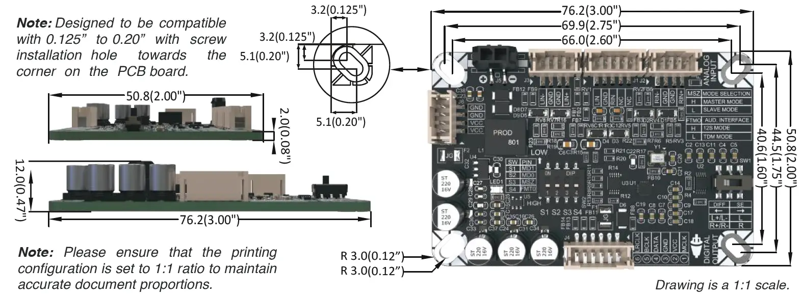
Mechanical Drawing
(Nominal Dimension, mm(inch))
Note: Designed to be compatible with 0.125” to 0.20” with screw installation hole towards the corner on the PCB board.
Safety Precautions
CAUTION Indicates a potentially hazardous situation which, if mishandled, could result in moderate or minor personal injury, and/or property damage.
When using the ASCM-A2D audio analog to digital module, prioritize safety for the board, connected devices, and user well-being. Verify power supply voltage and current meet specifications to prevent damage or hazards. Disconnect power before handling cables to avoid electric shock. When connecting external audio sources, ensure they’re powered off to prevent surges or interference. Verify compatibility with board’s input specs to avoid overload or distortion. Handle the board carefully to avoid damage from moisture or dust. Follow assembly instructions closely, checking connections to prevent issues, ensuring safe operation, and maximizing performance and lifespan.
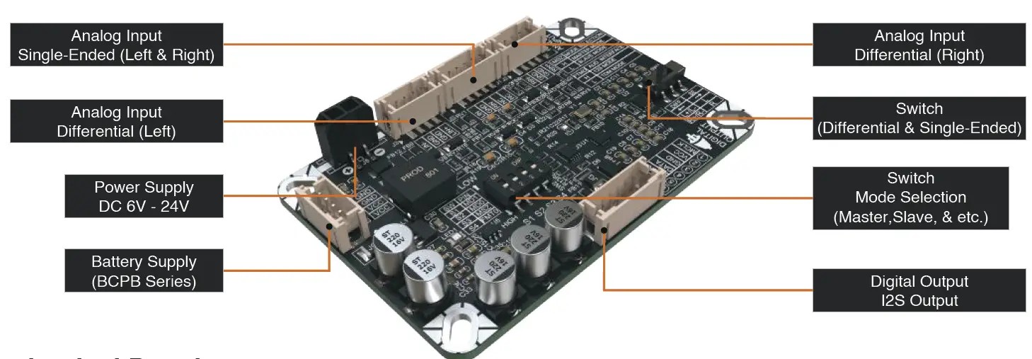
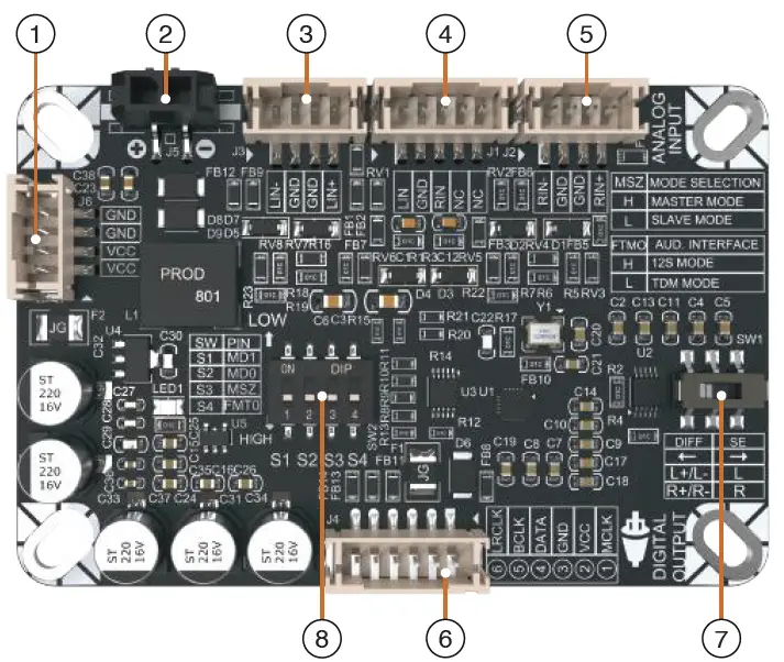
Connector(s) & Switch(s) Layout
ASCM-A2D Audio ADC Module
| SWITCH | CIRCUITS | |
| S1 | 1 | MD1 |
| S2 | 2 | MD0 |
| S3 | 3 | MSZ |
| S4 | 4 | FMT0 |
| OPERATION MODE | ||
| MSZ | HIGH | LOW |
| Master Mode | Slave Mode | |
| ASI FORMAT | ||
| FMT0 | HIGH | LOW |
| I2S Mode | TDM Mode | |
| SLAVE MODE | ||
| DECIMATION FILTER SELECTION | ||
|
MDO |
HIGH | LOW |
| Low Latency | Linear Phase | |
| DRE SELECTION | ||
|
MD1 |
HIGH | LOW |
| Enabled | Disabled | |
| MASTER MODE | ||
| SYS. CLOCK SELECTION | ||
|
MDO |
HIGH | LOW |
| 512 * fs | 256 * fs | |
| MD1 | MCLK | |
Connector(s)
- Battery Supply Input (BCPB Series)(JST PH 4-Circuits):
- Battery support voltage range (6V – 24V).
- Compatible with the BCPB series.
- Power Supply Input (Micro-Fit 1×2 CKT):
- DC supply voltage range (6V – 24V)
- Reduce the risk of power interruptions.
- Differential LEFT Audio Input (JST PH 4-Circuits):
- Used for differential audio input signal(s).
- Specified for two(2) complementary signals with opposite polarities for LEFT channels.
- Single-Ended LEFT & RIGHT Audio Input (JST PH 5-Circuits):
- Used for single-ended audio input signal(s).
- Specified for two(2) single-channels which are LEFT channels and RIGHT channels.
- Differential RIGHT Audio Input (JST PH 4-Circuits):
- Used for differential audio input signal(s).
- Specified for two(2) complementary signals with opposite polarities for RIGHT channels.
- 12S Audio Output (JST PH 6-Circuits):
- Used for digital Inter-Integrated Circuit Sound (I2S) output.
- High-quality digital audio data.
- Reliable power supply for audio performance.
Switch(s)
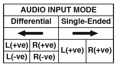
- DPDT Switch (Dual Pole Double Throw):
- Able to operate both audio input selection mode between differential mode and single-ended mode.
- Slide Left for differential mode.
- Slide Right for single-ended mode.
- SPST Switch (Single Pole Single Throw):
- Able to switch mode between master mode and slave mode.
- Support audio bus interface including audio serial interface (ASI) format, system clock selection, decimation filter and dynamic range enhancer (DRE) selection.
- Slide-Up for LOW.
- Slide-Down for HIGH.
- Switch (S1) for MD1 mode.
- Switch (S2) for MD0 mode.
- Switch (S3) for operation mode.
- Switch (S4) for ASI format mode.
Port(s) Layout
Connecting the ASCM-A2D Audio ADC Module
2. Micro-Fit 1×2 CKT (J5)
• Power supply voltage range from 6V to 24V.
• Connect Pin-1 to VCC and Pin-2 to Ground (GND).
1. JST PH 4-Circuits (J6)
• Battery supply voltage range from 6V to 24V.
• Connect Pin-1 and Pin-2 to VCC and Pin-3 and Pin-4 to Ground (GND).
• Support external connection from BCPB series.
6. JST PH 6-Circuits (J4)
• I2S digital audio output signals.
• Connect Pin-1 to (MCLK/MD1), Pin-4 to (DATA), Pin-5 to (BCLK) and Pin-6 to (LRCLK).
• Connect Pin-2 to VCC.
• Connect Pin-3 to Ground (GND).
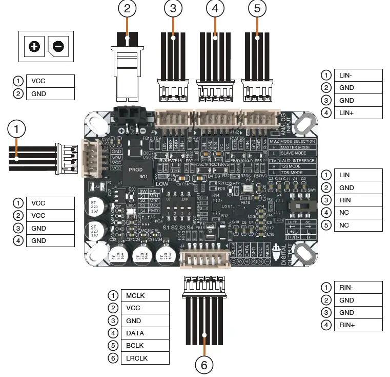
3. JST PH 4-Circuits (J3)
• Specified for differential signal(s) Left channel.
• Connect Pin-1 to Negative(-) Left channel.
• Connect Pin-4 to Positive(+) Left channel.
• Connect Pin-2 and Pin-3 to Ground (GND).
4. JST PH 5-Circuits (J1)
• Specified for single-ended signal(s) Right and Left channel.
• Connect Pin-1 to Positive(+) Left channel.
• Connect Pin-3 to Positive Right channel.
5. JST PH 4-Circuits (J2)
• Specified for differential signal(s) Right channel.
• Connect Pin-1 to Negative(-) Right channel.
• Connect Pin-4 to Positive(+) Right channel.
• Connect Pin-2 and Pin-3 to Ground (GND).
Electrical and Audio Performance Parameters
Electrical and audio performance specifications are typical at +25°C, powered by 12V DC, unless subject to change without notice. Combination with any add-on module(s) are not tested together.
ASCM-A2D Electrical Performance Parameters
| Parameter | Conditions | Min. | Typ. | Max. | Unit |
| Operating Voltage | DC Supply Voltage | 6 | 12 | 24 | VDC |
| Sampling Rate | – | 8 | 48/96 | 192 | kHz |
| Rated Current | When operating voltage (VCC = 12V) | 0.08 | 0.12 | 0.3 | A |
| Idle Power | When operating voltage (VCC = 12V) | 1.35 | 1.5 | 1.65 | W |
|
Output I2S Parameter |
44.1-48/96kHZ/ 24-bit
(Only this parameter has been tested) |
– |
48 |
– |
kHz |
| Input Impedance | SE ; DIFF | – | 2.5 | – | kΩ |
| Operating Temperature | Operating ambient temperature | -20 | 25 | 65 | °C |
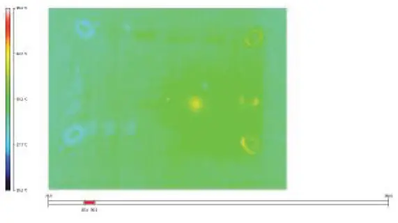
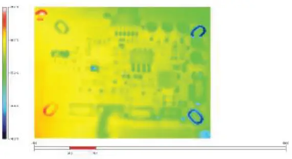
Thermal Image of ASCM-A2D
Condition 1:
- Test Setup: ASCM-A2D board tested at 25°C
- Load: Full load (1kHz audio)
ASCM-A2D Audio Performance Parameters
| Parameter | Conditions | Min. | Typ. | Max. | Unit |
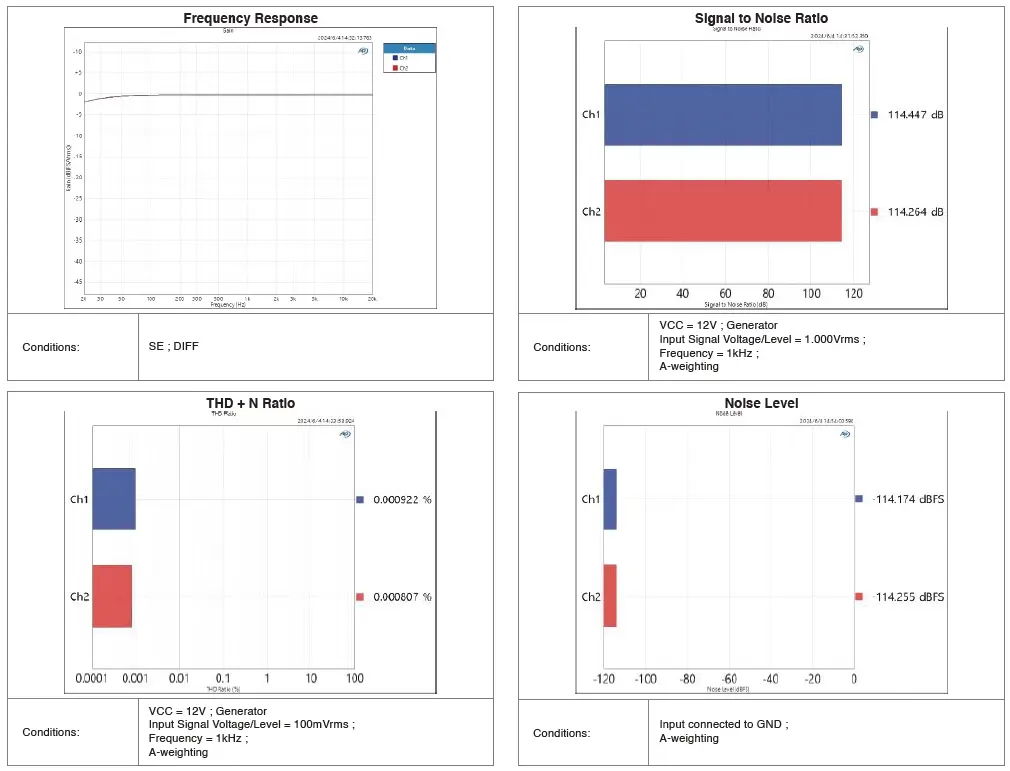
| Frequency Response | VIN = 100mVrms, (VCC = 12V) | 0.02 | – | 20 | kHz |
| Gain | SE ; DIFF | – | -0.31 | – | dB |
| Input Sensitivity (RMS) | SE ; DIFF | – | 0.1 | – | mV |
| Bandwidth @ ± 3dB | – | 20 | – | 20k | Hz |
| Total Harmonic Distortion (THD + N) | VCC = 12V ; Generator
Level = 100mVrms ; A-weighting |
– |
0.00047 |
– |
% |
|
Output Noise Level |
Input connected to ground (GND) ; A-weighting |
– |
0.97 |
– |
μVrms |
| Signal-to-Noise Ratio (SNR) | VCC = 12V ; Generator
Level = 1.000Vrms ; A-weighting |
– |
119.93 |
– |
dB |
Condition 2:
- Test Setup: ASCM-A2D board tested at 65°C
- Load: Full load (1kHz audio)
Note: ASCM-A2D do provide reverse polarity protection, BUT extreme caution must be exercised to ensure correct polarity during connection. Permanent damage caused by reverse polarity will not be covered under warranty.
Audio Performance Metrics
Graphs for Frequency Response, Signal to Noise Ratio, Noise Level, and THD+N Ratio
Sure Electronics Co., Ltd.
Professional Industrial Audio Solution Provider
3F, Building F6, No. 9, Weidi Road, Xianlin, Qixia Dist., Nanjing, China.
+86(25)8526-0046 | info@sure-electronics.com
To view our products and purchase, please visit our website: store.sure-electronics.com

58-7-2, Jalan Cantonment,
Wisma Fortune Heights, 10250, Pulau Pinang, Malaysia.+60(4)2189323 l info@wondom.com
(Please use phone calls or email instead of WhatsApp or iMessage.)

Warranty Terms and Product Usage Restrictions
Wondom products come with a one-year warranty starting from the date of purchase. Customers are responsible for the cost of returning the goods to the seller, and by making a purchase, you agree to this condition. Due to the nature of DIY products, visible damage or use on screw holes or tinning of solder pads directly invalidates the warranty. Damage caused by the use of incorrect power sources, such as exceeding the specified voltage range or reverse polarity, is not covered under warranty. All Wondom products undergo through testing before shipment. We do not accept bulk returns after a bulk purchase. If you are unsure of the quantity you need, please purchase the appropriate quantity as needed. All Wondom products are intended for DIY use only and do not support any industrial applications. The rated operating temperature range is -20°C to 65°C.
Origin and Design Location
All WONDOM products are designed, manufactured, and assembled in Malaysia. They may be shipped from either Malaysia or China. The country of origin for these product is Malaysia.
Specifications are subjected to change without any further notice. Copyright © 2023 by WONDOM – Industrial Audio Vendor. All rights reserved. For more information please visit www.wondom.com
Documents / Resources
 |
WONDOM ASCM-A2D Audio ADC Module [pdf] User Manual ASCM-A2D Audio ADC Module, ASCM-A2D, Audio ADC Module, ADC Module, Module |