![]() TIMECORE
TIMECORE
MANUAL
© VISUAL PRODUCTIONS BV
WWW.VISUALPRODUCTIONS.NL
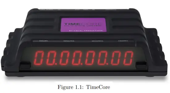
TimeCore Time Code Display
Revision History
| Revision | Date | Author(s) | Description |
| 5 | 17.12.2024 | FL | Updated monitors and installation pages. Added modes page. Fixed missing references. |
| 4 | 05.07.2023 | ME | FCC declaration. |
| 3 | 07.06.2018 | ME | Updated vManager chapter to reflect app-store distribution. Moved majority of Kiosc information to a dedicated Kiosc manual. Added discussion on password and share analytics. |
| 2 | 10.11.2017 | ME | Added: RTP-MIDI, Rackmount accessory, MSC API & password protection feature. Replaced VisualTouch info by Kiosc. |
| 1 | 10.05.2016 | ME | Initial version. |
©2024 Visual Productions BV. All rights reserved.
No parts of this work may be reproduced in any form or by any means – graphic, electronic, or mechanical, including photocopying, recording, taping, or information storage and retrieval systems – without the written permission of the publisher.
While every precaution has been taken in the preparation of this document, the publisher and the author assume no responsibility for errors or omissions, or for damages resulting from the use of information contained in this document or from the use of programs and source code that may accompany it. In no event shall the publisher and the author be liable for any loss of profit or any other commercial damage caused or alleged to have been caused directly or indirectly by this document.
Due to the dynamic nature of product design, the information contained in this document is subject to change without notice. Revisions of this information or new editions may be issued to incorporate such changes.
Products that are referred to in this document may be either trademarks and/or registered trademarks of the respective owners. The publisher and the author make no claim to these trademarks.
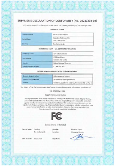
![]() Declaration of Conformity
Declaration of Conformity
We, manufacturer Visual Productions BV, herby declare under sole responsibility, that the following device:
TimeCore
Conforms to the following EC Directives, including all amendments:
EMC Directive 2014/30/EU
And the following harmonized standards have been applied:
NEN-EN-IEC 61000-6-1:2019
The object of the declaration is in conformity with the relevant Union harmonisation Legislation.
Full name and identification of the person responsible for product quality and accordance with standards on behalf of the manufacturer
VISUAL PRODUCTIONS BV
IZAAK ENSCHEDEWEG 38A
NL-2031CR HAARLEM
THE NETHERLANDS
TEL +31 (0)23 551 20 30
WWW.VISUALPRODUCTIONS.NL
INFO@VISUALPRODUCTIONS.NL
ABN-AMRO BANK 53.22.22.261
BIC ABNANL2A
IBAN NL18ABNA0532222261
VAT NL851328477B01
COC 54497795
![]() QPS Evaluation Services Inc
QPS Evaluation Services Inc
Testing, Certification and Field Evaluation Body
Accredited in Canada, the USA, and Internationally
File
LR3268
CERTIFICATE OF COMPLIANCE
(ISO TYPE 3 CERTIFICATION SYSTEM)
| Issued to | Visual Productions BV |
| Address | Izaak Enschedeweg 38A 2031 CR Haarlem The Netherlands |
| Project Number | LR3268-1 |
| Product | Lighting Control System |
| Model Number | CueCore3, CueCore2, QuadCore, loCore2, TimeCore |
| Ratings | 9-24V DC, 0.5 A Powered by an approved LPS power supply, I/P:100-240Vac, 1.0A max 5060Hz, O/P: 12Vdc, 1A, 12W max |
| Applicable Standards | CSA C22.2 No 62368-1:19 Audio/Video, Information and communication technology equipment- Part 1 and UL62368-1- Audio/Video, Information and communication technology equipment- Part 1 |
| Factory/Manufacturing Location | Same as above |
Statement of Compliance: The product(s)/equipment identified in this Certificate and described in the Report covered under the above referenced project number have been investigated and found to be compliant with the relevant requirements of the above referenced standard(s) and versions. As such, they are eligible to bear the QPS Certification Mark shown below, in accordance with the provisions of QPS’s Service Agreement.
IMPORTANT NOTE
In order to maintain integrity of the QPS Mark(s), this certification will be revoked if:
- Compliance with the above-mentioned Standard(s) – including any, informed through QPS Standard Update Notice (QSD 55) issued in future – is not maintained, or
- The product/equipment is modified after certification is granted, without prior written consent from QPS.

Introduction
The TimeCore is a solid-state device for handling timecode. It is intended to be used for entertainment shows at events, concerts, festivals and in themed environments. The TimeCore will help in keeping the various show elements like sound, lighting, video, laser and special FX synchronised.
The TimeCore can generate timecode, it can convert it between different protocols and it can display any received timecode on its display. The unit features inbuilt web-server; this web-interface allows the user to configure the unit. The web-interface also enables other non-timecode protocols like UDP, OSC and sACN to be linked to certain timecode events. The TimeCore can be the bridge between timecode and other non-timecode show equipment such as video players, relays and dimmers. The TimeCore features a rich suite of protocols that include the two most popular timecodes in show business SMPTE and MTC. Furthermore, it has Art-Net timecode implemented, which has the advantage of being network-based.
This document discusses setting up the device and programming its internal software functions. At the time of writing this manual the TimeCore’s firmware was at version 1.14.
1.1 Compliance
This device is in compliance with the following regulations:
- CE
- UKCA
- FCC
- UL 62368-1
- CSA C22.2 62368-1:19
- EAC
1.2 Features
The feature set of the TimeCore includes:
- Ethernet port
- Programming via web-interface
- SMPTE
- MTC
- MIDI, MSC, MMC
- RTP-MIDI
- OSC, UDP, TCP
- Art-Net (data & timecode)
- sACN
- Large 7-segment LED display
- 2x user-definable push-button
- 9-24V DC 500mA (PSU included)
- Power over Ethernet (class I)
- Desktop or DIN Rail mounted (optional adapter)
- Operating temperature -20º C to +50º C (-4º F to 122º F)
- Compliance EN55103-1 EN55103-2
- Bundled with vManager and Kiosc software
1.3What’s in the box?
The TimeCore packaging contains the following items (see figure 1.2):
- TimeCore
- Power supply (inc. international plug set)
- Network cable
- Info card

1.4 Saving data to memory
This manual will describe how to configure the TimeCore and actions, tasks, etc. The unit’s web-interface is used for editing these kinds of elements. When changes are made, these changes are directly stored in the RAM memory of the TimeCore and the programming will directly influence the behaviour of the unit. RAM memory is, however, volatile and its content will be lost through a power cycle. For this reason the TimeCore will copy any changes in the RAM memory to its onboard flash memory. Flash memory retains its data even when not powered. The TimeCore will load all its data back from the flash memory upon startup.
This memory copy process is conducted automatically by the TimeCore and should not be of any concern of the user. One point of consideration is, however, that after making a change the unit should be given time to perform the copy to flash. As a rule of thumb, do not disconnect the power from the device within 30 seconds from making a programming change.
1.5 Further Help
If, after reading this manual, you have further questions then please consult the online forum at https://forum.visualproductions.nl for more technical support.
Protocols
The TimeCore is fitted with several communication ports and supports various protocols. This chapter describes these protocols and to which extent they are implemented in the TimeCore
2.1 SMPTE
SMPTE is a timecode signal which can be used to synchronise audio, video, lighting and other show equipment. The TimeCore supports receiving SMPTE that is transferred as an audio signal, also know as LTC timecode. The TimeCore can send and receive SMPTE.
2.2 MIDI
The MIDI protocol is intended for inter-connecting musical devices such as synthesisers and sequencers. Furthermore, this protocol is also very suitable to send triggers from one device to another and is often used to synchronise audio, video and lighting equipment. There is also a large collection of MIDI control surfaces available; user-interface consoles with knobs, (motorised-)faders, rotary-encoders, etc.
The TimeCore is fitted with both a MIDI input and a MIDI output port. It supports receiving and sending MIDI messages like NoteOn, NoteOff, ControlChange and ProgramChange.
2.2.1 MTC
MIDI Timecode (MTC) is the timecode signal which is embedded into MIDI.
The TimeCore supports receiving and transmitting MTC. It is not recommended to combine the use of MTC with ordinary MIDI as MTC consumes the bandwidth of the MIDI connection.
2.2.2MMC
MIDI Machine Control (MMC) is part of the MIDI protocol. It defines special messages for controlling audio equipment such as multi-track recorders. The TimeCore supports the sending of MMC commands; please refer to page 61.
2.2.3MSC
MIDI Show Control (MSC) is an extension of the MIDI protocol. It comprises of commands for synchronising show equipment like lighting, video and audio devices.
2.3RTP-MIDI
RTP-MIDI is an Ethernet-based protocol for transferring MIDI messages. It is part of the RTP (Real-time Protocol) protocol suite. RTP-MIDI is natively supported by the macOS and iOS operating systems. Through installing a driver, it is also supported on Windows.
Once the RTP-MIDI connection is established between the TimeCore and the computer, then software running on the computer will see the TimeCore s MIDI ports as if it was a USB connection MIDI interface.
2.4Art-Net
The Art-Net protocol primarily transfers DMX-512 data over Ethernet. The high bandwidth of an Ethernet connection allows Art-Net to transfer up to 256 universes.
The data sent out for Art-Net does put a certain load on the network, therefore it is recommended to disable Art-Net when not in use.
Additional to transmitting DMX-512 data, Art-Net can also be used for transferring timecode information for equipment synchronisation.
The TimeCore supports sending and receiving of Art-Net timecode as well as one universe of Art-Net data.
2.5sACN
The streaming Architecture of Control Networks (sACN) protocol uses a method of transporting DMX-512 information over TCP/IP networks. The protocol is specified in the ANSI E1.31-2009 standard.
The sACN protocol supports multi-cast in order to take efficient use of the network’s bandwidth.
The TimeCore supports sending and receiving of one sACN universe.
2.6TCP
The Transmission Control Protocol (TCP) is a core protocol of the Internet Protocol Suite. It is used for its reliable, ordered and error checked delivery of a stream of bytes between applications and hosts over IP networks. It is considered ’reliable’ because the protocol itself checks to see if everything that was transmitted was delivered at the receiving end. TCP allows for the retransmission of lost packets, thereby making sure that all data transmitted is received.
The TimeCore supports receiving TCP messages.
2.7UDP
User Datagram Protocol (UDP) is a simple protocol for sending messages across the network. It is supported by various media devices like video projectors and Show Controllers. It does not incorporate error checking, therefor it is faster than TCP but less reliable.
There are two ways how to have the TimeCore respond to incoming UDP messages. The API (see page 69) makes typical TimeCore functions available through UDP. Furthermore, custom messages can be programmed in the Show Control page (see page 26). This is also the place where to program outgoing UDP messages.
2.8OSC
Open Sound Control (OSC) is a protocol for communicating between software and various multi-media type devices. OSC uses the network to send and receive messages, it can contain various information.
There are apps available for creating custom-made user interfaces on iOS (iPod, iPhone, iPad) and Android. These tools allow to program fool-proof userinterfaces for controlling the device. E.g. Kiosc from Visual Productions.
There are two ways how to have the TimeCore respond to incoming OSC messages.
Firstly, the API (see page 68) makes typical TimeCore functions available through OSC. Secondly, custom messages can be programmed in the Show Control page (see page 26).
2.9DHCP
The Dynamic Host Configuration Protocol (DHCP) is a standardised network protocol used on Internet Protocol (IP) networks for dynamically distributing network configuration parameters, such as IP addresses.
The TimeCore is a DHCP client.
Installation
This chapter discusses how to set up the TimeCore.
3.1DIN Rail Mounting
The device can be DIN Rail mounted. The device is prepared for DIN Rail mounting by using the ’DIN rail holder TSH 35’ from Bopla (Product no. 22035000).
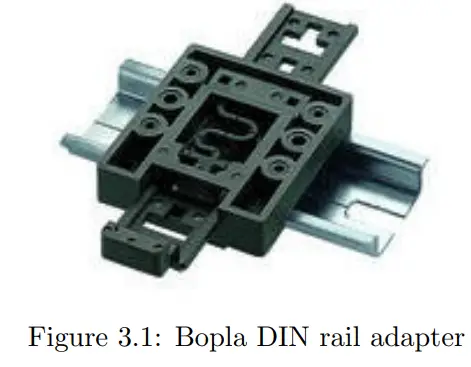
This adapter is – amongst others – available from:
- Farnell / Newark (order code 4189991)
- Conrad (order code 539775 – 89)
- Distrelec (order code 300060)
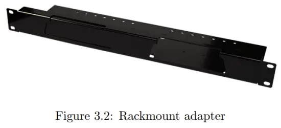
3.2Rackmount
There is an adapter available for mounting the TimeCore into a 19” rack . The rackmount adapter is 1U and is sold separately. It fits two units, however, it is supplied with one position closed by a blind panel, see figure 3.2.
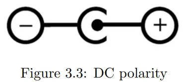
3.3Power
The TimeCore requires a DC power supply between Volt with a minimum of 500mA. The 2,1 mm DC connector is center-positive. The TimeCore is also Power-over-Ethernet (PoE) enabled. It requires PoE Class I.
Network
The TimeCore is a network capable device. A network connection between a computer and the unit is required to configure and program the TimeCore, however, once the device is programmed it is no longer necessary for the TimeCore to be connected to an Ethernet network.
There are multiple arrangements possible for connecting the computer and the TimeCore. They can be connected peer-to-peer, via a network switch or via Wi-Fi. Figure 4.1 illustrates these different arrangements.
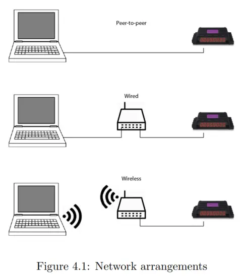
The Ethernet port on the TimeCore is auto-sensing; it does not matter whether a cross or straight network-cable is being used. Although the Ethernet port is classified as 100 Mbps, buffer limits may apply for specific tasks, such as API messages.
4.1 IP Address
The TimeCore supports both static IP addresses and automatic IP addresses.
By default, the TimeCore is set to ’DHCP’ in which it will be automatically assigned an IP address by the DHCP server in the network. The ’DHCP server’ is typically part of a network router’s functionality.
Static IP addresses are useful when there is no DHCP server in the network, for instance when there is a direct peer-to-peer connection between a TimeCore and a computer. It is also useful in permanent installations where the IP address of the TimeCore is known by other equipment and therefor should not change.
When using DHCP there is often the risk of automatically being given a new IP address in the event that the DHCP server is replaced. When using static IP addresses make sure that all equipment on the network have unique IP addresses within the same subnet.
The TimeCore’s LED helps to determine which kind of IP address is set. The LED will indicate red when using DHCP and it will indicate white in the case of a static IP address.
There are three ways to change the IP address setting of the TimeCore.
- vManager can be used to detect a TimeCore on the network. Once found, the vManager software (figure chapter 10) allows for changing the IP address, subnet mask and DHCP settings.
- If the IP address is already known then browsing to this address using the computer’s browser will show the TimeCore’s web-interface. The Settings page on this web-interface enables changing the same network related settings.
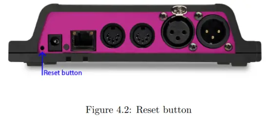
- By briefly pressing the reset button on the device it toggles between static and automatic IP addresses. By pressing and holding the reset button (see figure 4.2) on the device for 3 seconds, it will reconfigure the unit to the factory default IP address and subnet mask. No other settings will be changed. The default IP address is 192.168.1.10 with the subnet mask set to 255.255.255.0.
4.2Web-interface
The TimeCore features an inbuilt web-server. This web-interface can be accessed via a standard browser. It is recommended to use any of the following browsers:
- Microsoft Edge
- Google Chrome (v102 or higher)
- Apple Safari (v15 or higher)
- Mozilla Firefox (v54 or higher)
The web-interface enables you to configure and program the TimeCore. When browsing to the unit the home page (figure 4.3) will appear first. The home page is read-only; it provides information but does not allow for changing any setting. The other pages present many settings that can be edited. These pages will be discussed in the subsequent chapters.

4.2.1Uptime
This field indicates how long the unit has been alive since its last reboot.
4.2.2Last Server Poll
Indicates the last time the time & date was fetched from an NTP time server.
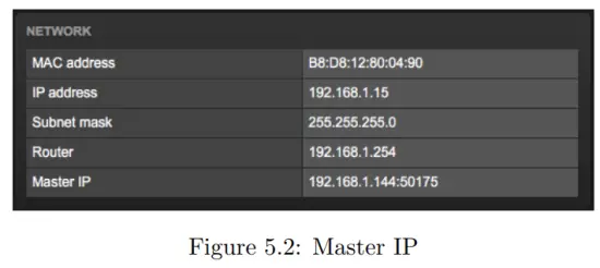
4.2.3Master IP
When the unit is not in Stand Alone mode, then this field displays the IP address of the system that is mastering this TimeCore. Refer to chapter 5 for more information on operating modes.
4.3Access via Internet
The TimeCore can be accessed through the Internet. There are two ways to achieve this: Port Forwarding and VPN.
- Port Forwarding Is relatively easy to setup in the router. Each router is different so it is advised to consult the router’s documentation (sometimes it is referred to as NAT or Port-Redirecting). Please note that port forwarding is not secure, since anybody could access the TimeCore this way.
- Accessing via a Virtual Private Network (VPN) tunnel requires more setup efforts, also the router needs to support the VPN feature. Once set up, this is a very secure way to communicate with the TimeCore. A VPN is a network technology that creates a secure network connection over a public network such as the Internet or a private network owned by a service provider. Large corporations, educational institutions, and government agencies use VPN technology to enable remote users to securely connect
to a private network. For further information about VPN please refer to http://whatismyipaddress.com/vpn.
Operating Modes
A TimeCore can operate in three modes, each mode resulting in a different behaviour of the device.
- Stand-alone
- Slave
- CueluxPro
By default the TimeCore operates in the Stand-alone mode.

The status bar at the bottom of the web-interface (figure 5.1) indicates the current operating mode. When mastered by CueluxPro the home page of the web-interface shows the IP address of the CueluxPro system (figure 5.2).
5.1Stand-alone mode
In this mode the TimeCore is an autonomous device for controlling lighting.
Typically it is loaded with lighting content and programmed to respond to external triggers and/or internal scheduling. This is the default behaviour of a TimeCore; the stand-alone mode is active whenever the TimeCore is not in the slave or CueluxPro mode.
5.2Slave Mode
Some demanding lighting designs can require more than four universes of DMX.
When multiple TimeCore units are combined to create a large multi-universe system there is the need for synchronisation of those TimeCore devices. The Slave mode facilitates this. See figure 5.3.
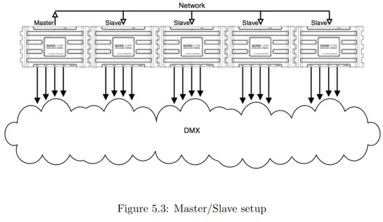
When in Slave mode the TimeCore is taken over by a master-TimeCore and is no longer responsible for its playbacks and scheduling; the master takes care of this. All the slave requires is to contain the lighting content in its tracks.
The master-TimeCore will control all its slaves to activate the same tracks and keep the playback of those tracks synchronised.
It is necessary to put all action-programming in the master-TimeCore. In fact, the playback information inside the slaves will be overwritten by the master.
The master does this because it stores a copy of its playback-data in each slave to enable the slave to continue autonomously in case the communication between master and slave is interrupted.
The logical place for the action lists and action for a master/slave system is also inside the master, however, it is allowed to place actions in a slave and they will get executed.
5.3CueluxPro Mode
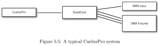
CueluxPro (see figure 5.4) is a software-based lighting console that is bundled with the TimeCore. The purpose of the TimeCore in this mode is to be an interface between CueluxPro and the DMX lighting fixtures. Therefore the TimeCore will forward the data received from the CueluxPro software to its DMX outlets. During this mode all internal playback and scheduling within the TimeCore is suspended. Figure 5.5 illustrates a typical CueluxPro/TimeCore system.

The TimeCore enters the CueluxPro mode as soon as it is patched to one or more universes within the CueluxPro software. This mode is exited by unpatching the TimeCore or closing down the CueluxPro software.
Using the CueluxPro software in combination with the TimeCore results in a lighting control system with a larger feature set than using the TimeCore on its own in the stand-alone mode. CueluxPro features:
- Personality library with 3000+ fixtures
- FX Generator
- Matrix Pixel-mapping
- Groups
- Palettes
- Timeline editor
CueluxPro can also be used for generating the lighting content that can be uploaded to the TimeCore. After uploading, the TimeCore can continue to be used stand-alone. For information on how to use CueluxPro please refer to the CueluxPro manual on the Visual Productions website. This manual provides instructions for connecting to CueluxPro and uploading content to the TimeCore.
Show Control
The TimeCore can interact with the outside world; it can receive messages and values through various protocols and it can send out many protocols. It is possible to automate the TimeCore by having it respond automatically to incoming signals. An example of this would be to start the time-code clock upon receiving a specific UDP network message. The Show Control page (See figure 6.1) enables this kind of programming to be made.

The Show Control page presents a system of ’actions’. A signal that the TimeCore needs to respond to or perhaps convert into some other signal, needs to be expressed in an actions. Converting timecode protocols is the exception; this can be done in the Settings page (see page 36).Before programming actions
please consider the Show Control structure in figure 6.2.
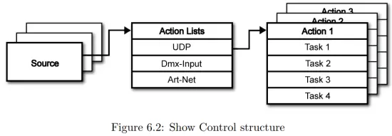
The TimeCore is capable of listening to various protocols. These available protocols are listed in Sources, however, the TimeCore can only actively listen to 8 protocols at once. The active protocols are listed in ’Action Lists’. Each action list can contain actions. Within a protocol/source each individual signal requires its own action. For example, when listening to channel 1 and 2 on the incoming DMX, the DMX action list needs two actions; one for each channel.
Inside the action we define the trigger and tasks. The trigger specifies for which signal to filter. In the above DMX example the trigger would be set to ’channel 1’ and ’channel 2’ respectively. The tasks determine what the TimeCore will do when this action is triggered. Several tasks can be placed in the action. There are tasks available for a wide range of TimeCore features and external protocols. Task types are detailed in Appendix C on page 60.
Please consult the API appendix on page 68 before implementing incoming OSC or UDP messages; the API already exposes typical functionality through OSC and UDP and therefor it might not be necessary to implement custom messages.
6.1Sources and Action Lists
The Sources listing presents all protocols that the TimeCore is capable of receiving.
It also includes internal features that can create events that can be used for triggering actions, such as the power-up event. These sources are available, however, they will only be actively listened to once moved to the action-list table.
| Buttons | One of the two front side buttons is pushed |
| MIDI | MIDI messages |
| RTP-MIDI | RTP-MIDI network messages |
| UDP | UDP network messages |
| TCP | TCP network messages |
| OSC | OSC network message |
| Art-Net | Art-Net DMX data |
| sACN | sACN DMX data |
| Timecode | Timecode signal, specify the incoming timecode protocol on the Settings page. |
| Kiosc | Triggers from Kiosc. For each Action various controls can be chosen such as buttons and sliders, colour picker etc. The order of the actions will control the arrangement in Kiosc. |
| Randomiser | The randomiser can generate a random number |
| System | Events such as ’Power on’ |
| Variable | The Variable source works in combination with the variable task (For more information about the Variable task please refer to Task Types). The Variable task will set a value of which an enabled action-list type with Variable as Source will use as a trigger. The TimeCore will not keep the values of the 8 variables between power-cycles. |
| Timer | There are 4 internal timers in the TimeCore. An event will be raised when a timer expires. Timers are set and activated by the Timer tasks. |
| User List 1-4 | These action-lists will never trigger an event, however, they are useful for advanced programming. |
Action-lists can be temporarily suspended by disabling their checkbox in the Show Control page. There is also a task available to automate changing the state of this checkbox.
6.2Actions
Actions are executed when a certain signal is received. This signal is defined by the trigger. A trigger is always relative to the action-list the action belongs to.
For example, when the trigger-type is set to ’Channel’ then it refers to a single DMX channel if the action is placed inside a ’DMX Input’ list and it means a single Art-Net channel if the action resides in an Art-Net action-list.
A trigger is determined by the trigger-type, trigger-value and trigger-flank fields.
Although these fields are not applicable for all action-lists and are therefor sometimes omitted in the web GUI. The trigger-type field specifies what kind of signal the action will be triggered by. For example, when making an action in the Button list there is the choice between ’Short press’ and ’Long press’ trigger-types. The trigger-value specifies the actual signal value. In the Button example the trigger-value denotes which button.
In some action-lists actions do also need to specify the trigger-flank. The flank further specifies the value that the signal should have before triggering the action. For example, when an action is triggered from a Kiosc list and it is linked to a button in the Kiosc software, the flank will determine whether to trigger only when the button goes down or only when it goes up. Appendix B provides an overview of the available trigger-types.
An action-list can have up to 48 actions, system-wide there is a maximum of 64 actions.
6.3Tasks
Tasks are added to an action in order to specify what to do when it gets executed.
Up to 8 tasks can be included in an action, system-wide there is a maximum of 128 tasks. The tasks are executed in the order of the list. There is a wide selection of tasks available to choose from, they include altering any of the internal software features like time-code clock and the LED display, also sending out messages through any of the supported protocols.
The tasks are organised in categories. Once a task is chosen from these categories each task allows for further choice between several Features and Functions.
Tasks contain up to two parameters that might be required for its execution.
A task can be tested by selecting it and pressing the ’execute’ button in the action-edit dialog. The complete action can also be tested; go to the Show Control page, select the action and press the ’execute’ button.
Appendix B provides a detailed overview of the available tasks, features, functions and parameters.
6.4Templates
The Show Control page presents a list of templates. A template is a set of actionlist, actions and task. These templates configure the TimeCore to perform typical functions; for example control the time-code clock with the two pushbuttons or show the time-code status on the LED display.
The templates thus save time; otherwise actions should have been set up manually.
They can also function as a guide to soften the learning curve on actions; a lot can be learned from adding a template and then exploring the actions and tasks it created. Please note that some templates require settings to changed in the settings page. Appendix A gives an overview of the available templates.
6.5Variables
Variables are internal memories that can hold a value; a number in the range of [0,255]. There are 8 variables and they are typically used for advanced show control programming. In the IoCore2, the content of the variable is not stored between power cycles.
Variables can be set by tasks. Variables can be added as sources in order to have actions triggered when a variable changes value.
6.6Randomizer
The randomizer is an internal software feature that can generate a (pseudo)random number. This is useful for having an event trigger a random lighting scene in a themed environment. The randomizer is activated by the Randomizertask. The result of the randomizer’s calculation can be obtained by catching the event in the Randomizer-actionlist.
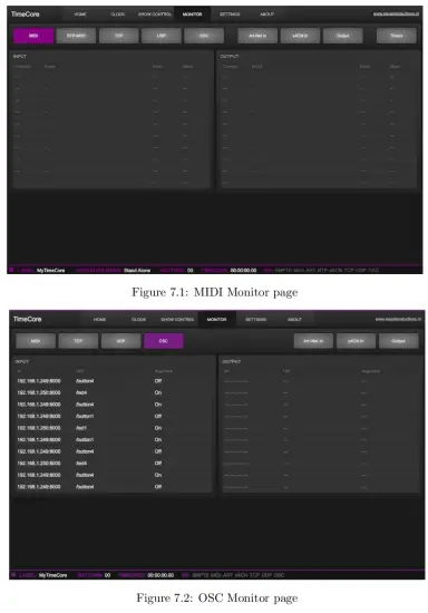
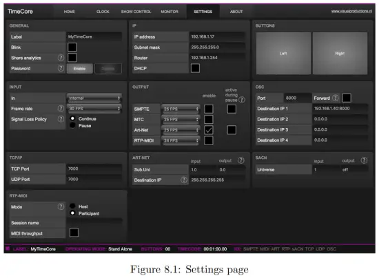
Monitors
This page allows the user to inspect the incoming and outgoing data, both MIDI-type data (See figure 7.1) as well as control messages (See figure 7.2).
Monitoring incoming and outgoing data can help the user troubleshoot during programming.
In the Monitor page four different sources of input can be found (MIDI, RTPMIDI, Art-Net and sACN), along with the control input and output sources (TCP, UDP and OSC).As well as access to the data stored in the 4 timers and 10 variables.
Settings
The TimeCore’s settings are organised into sections, see the Settings page figure 8.1. This chapter will discuss each section.
8.1General
You can change the TimeCore’s label. This label can be used to distinguish the unit in a set-up with multiple devices.
By enabling the Blink checkbox the device’s LED will blink to help to identify it amongst multiple devices.
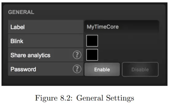
The API commands discussed in appendix D start with a prefix that is set to core by default. When using multiple devices from Visual Productions it can be useful to assign unique labels to these prefix, especially when using broadcasted messages. Read more about feedback loops in paragraph D.4.
Unauthorised users can be prevented from making changes to the TimeCore by enabling the Password protection. Once enabled, the password can be disabled via the web-interface (using the Disable button) and the reset button (see figure 4.2). Long-press the reset button to disable the password protection; this will also revert the unit’s static IP back to the default factory settings.
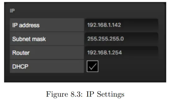
8.2 IP
The IP fields are for setting up the IP address and subnet mask of the TimeCore.
The Router field is only required when Port Forwarding is used. You can also enable or disable the DHCP feature (For more information see chapter 4 at page 18).
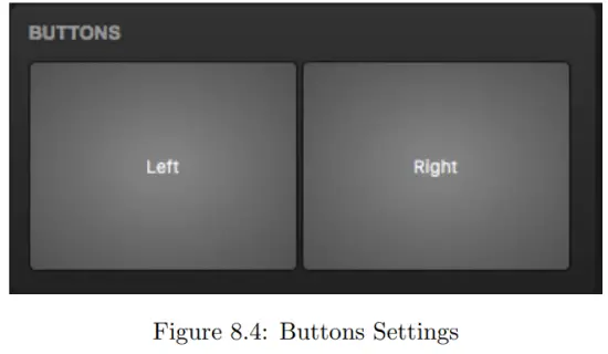
8.3Buttons
The two buttons in the web-interface mimic the two push-buttons on the physical device. These software buttons are useful for testing or controlling the unit when it is placed out of your reach.
8.4 Input
This section determines the timecode source for the TimeCore. The options are:
| Source | Description |
| Internal | Timecode will be generated internally by the TimeCore |
| SMPTE | LTC signal received on SMPTE IN connector |
| MTC | MTC signal received on MIDI IN connector |
| Art-Net | Art-Net timecode received via the network port |
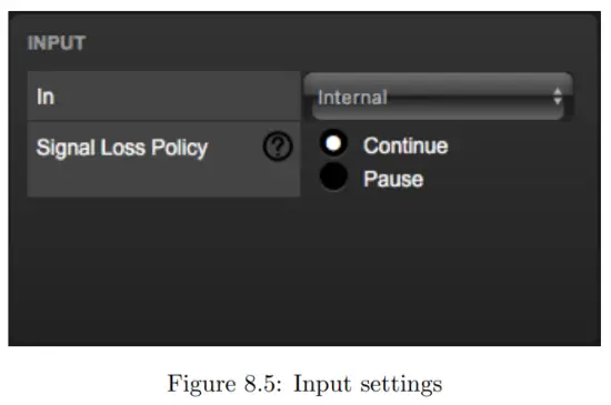
The SMPTE and Art-Net protocol do not offer means to distinguish a signal loss from a ’pause’ of the time. Therefor, the ’Signal Loss Policy’ allows you to control a drop in the timecode signal should be interpreted.
| Policy | Description |
| Continue | In the case of a signal loss the TimeCore will continue the timecode by using its internal clock. When the signal reappears the TimeCore will sync again to it. |
| Pause | The TimeCore will pause the timecode when the signal is lost. It will continue the timing as soon as the signal is restored. |
8.5Output
This section controls if any timecode protocol is transmitted from the TimeCore.
Each timecode protocol has its own frame-rate setting.
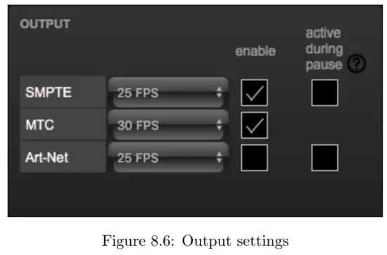
The SMPTE and Art-Net protocol do not offer means to indicate a ’pause’ of the timecode signal. Therefor, the TimeCore offers an ’active during pause’ checkbox to control the behaviour of the SMPTE and Art-Net signal during a pause state.
When disabled, both SMPTE and Art-Net signal will cease; no signal will be generated. In this case it is hard for the recipient to determine the difference between a ’pause’ and ’signal loss’.
When ’active during pause’ is enabled for SMPTE then the TimeCore will generate invalid SMPTE frames during the pause. This enabled the recipient to still detect activity on the SMPTE line (this would not be the case during a signal loss). When the checkbox is enabled for Art-Net then the TimeCore will continue repeating the last timecode frame during the pause.
8.6OSC
External equipment sending OSC messages to the TimeCore need to be aware of the number specified in the ’Port’ field. This is the port the TimeCore listens to for incoming messages.
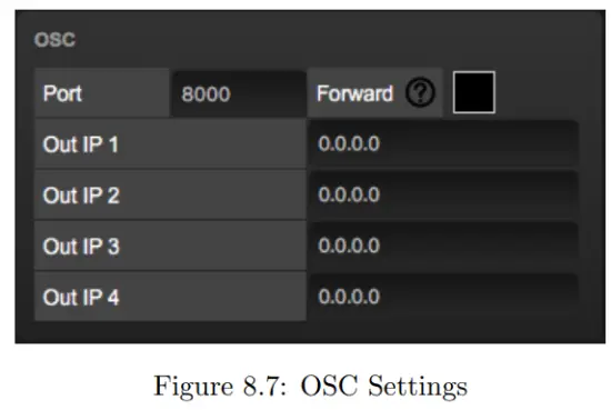
The TimeCore will send its outgoing OSC messages to the IP addresses specified in the ’Out IP’ fields. Up to four IPs can be specified here. Use the ’ipaddress:port’ format in these fields, e.g. ”192.168.1.11:9000”. If a field should not be used then it can be filled with IP 0.0.0.0:0. It is possible to enter a broadcast IP address like 192.168.1.255 in order to reach more than four recipients.
Enabling the Forward checkbox will have the TimeCore copy every incoming OSC message and send it the addresses specified in the ’Out IP’ fields.
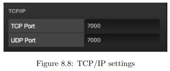
8.7TCP/IP
Defines the listening ports for TCP and UDP messages. External systems intending to send TCP or UDP message to the TimeCore need to know the unit’s IP address and this port number. By default both ports are set to 7000.
8.8Art-Net
The Art-Net (DMX data) feature in the TimeCore supports one universe out and one universe in. These universes can be mapped to any of the 256 available universes in the Art-Net protocol. The universe is entered in the ’subnet.universe’ format, i.e. the lowest universe number is written as ’0.0’ and the highest universe number is denoted as ’15.15’. The outgoing Art-Net transmission can be disabled by entering ’off’ in the output field.
The destination IP determines where the outgoing Art-Net data will be send to.
Typically, this field contains a broadcast address like 2.255.255.255 which will send the Art-Net data to the 2.x.x.x IP range. Another typical Art-Net broad-
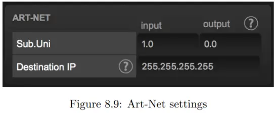
cast address is 10.255.255.255. When using broadcast address 255.255.255.255 then all the devices on the network will receive the Art-Net data.
It is also possible to fill in a unicast address like 192.168.1.11; in this case the Art-Net data will be send to one IP address only. This keeps the rest of the network clean of any Art-Net network messages.
8.9sACN
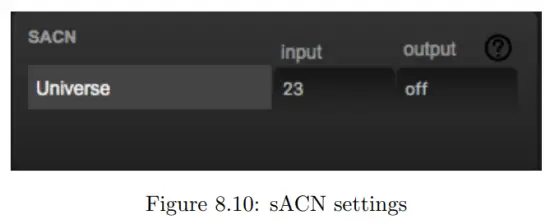
The TimeCore supports one incoming sACN universe and 1 outgoing universe.
Each universe field should hold a number in the range of [1,63999]. Outgoing sACN transmission can be disabled by entering ’off’ into the sACN output field.
8.10RTP-MIDI
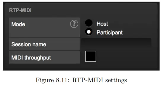
Refer to chapter 9 for a detailed discussion on how to setup a RTP-MIDI connection.
RTP-MIDI
The TimeCore supports RTP-MIDI. It is a protocol for sending MIDI messages over Ethernet. This chapter discussed how to setup the connection between the TimeCore and a computer.
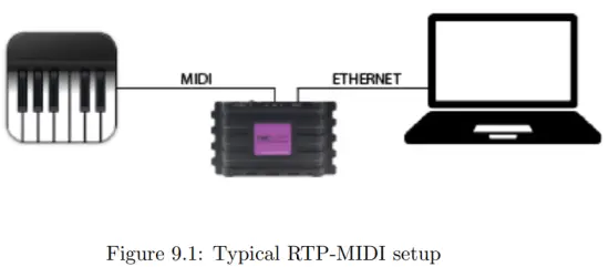
Figure 9.1 illustrates a typical RTP-MIDI setup. The computer connects to the TimeCore via Ethernet. This allows the computer to send MIDI messages to the TimeCore. These messages can be used to control the TimeCore internally.
Alternatively, the messages can be forwarded to the physical MIDI port on the TimeCore, using the TimeCore as a MIDI interface.
Likewise, MIDI messages generated by the TimeCore internally can be received at the computer via RTP-MIDI. As well as MIDI messages received on the physical MIDI port.
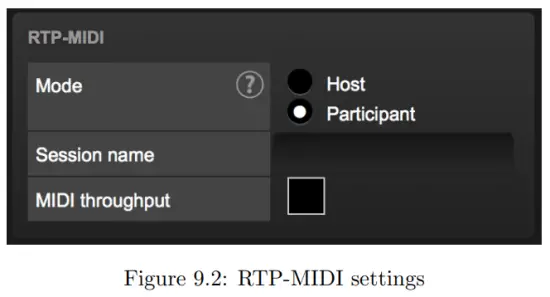
The MIDI Throughput checkbox in figure 9.2 enables the RTP-MIDI forwarding to the TimeCore’s physical MIDI port. When disabled, the RTP-MIDI messages received from the computer can only be used internally in the TimeCore.
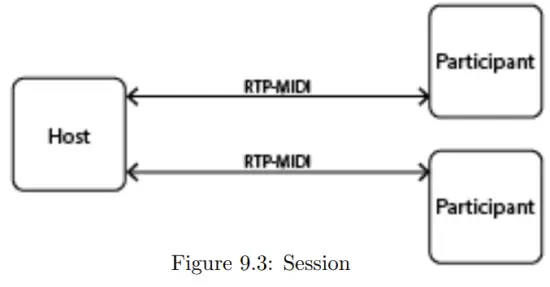
9.1Sessions
In order to communicate via RTP-MIDI a ’session’ is required. A RTP-MIDI session is made up by one host and one or more participants. A participant connects to a host. This host should therefor already be made available on the network.
The TimeCore can act either as host or as participant. This choice is made in the settings page (see figure 9.2).
9.1.1Host
When configured as host the TimeCore will create a session. The name of this session is derived from the TimeCore’s label plus its serial number. For example a TimeCore with label ’MyTimeCore’ and serial 201620001 will result in session name mytimecore201620001.
When a TimeCore sends a message via RTP-MIDI, this message will be send to all participants. The TimeCore is capable of maintaining a connection with up to 4 participants at the same time.
9.1.2Participant
If the TimeCore is configured as participant it will attempt to connect to a session with the name as defined in the ’Service name’ field (see figure 9.2).
9.2Setting up the computer
The computer also needs to either host a session or join an existing session.
This paragraph describes how to set it up on macOS and Windows.
9.2.1macOS
RTP-MIDI is natively supported by the macOS operating system. Please follow the next steps to set it up.
- Open Application/Utilities/Audio Midi Setup
- Click ’Window’ and choose ’Show Midi Studio’
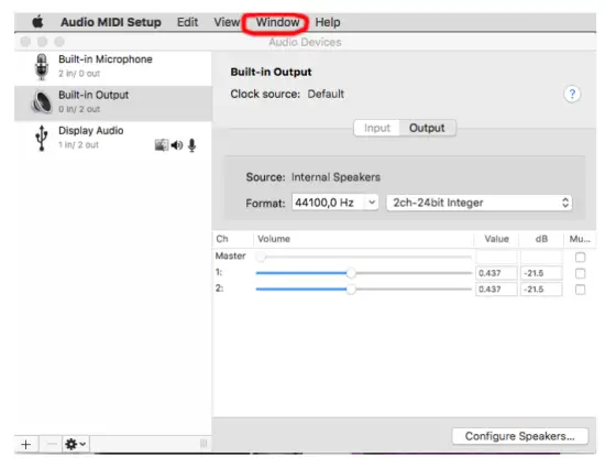
- Double-click on ’Network’

- Continue with ’Host’ setup on page 42 or ’Participant’ setup on page 43.
9.2.2Windows
The Windows OS supports RTP-MIDI with the aid of a driver. We recommend the rtpMIDI driver from Tobias Erichsen. It can be downloaded from http://www.tobias-erichsen.de/software/rtpmidi.html. Install the driver and open it. Then continue with ’Host’ setup on page 42 or ’Participant’ setup on page 43
9.2.3Host + Participant
Follow the next steps for either setting up your computer as host or as participant.
- If there are no sessions already, then add a session using the + button underneath the My Sessions section.

- Choose a local name and a Bonjour name.

- Enable the session.
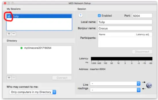
- Set ’Anyone’ in the ’Who may connect to me’ field.

9.2.4Participant
To join a session created by another host, select the session in the Directory list and click on the Connect button.
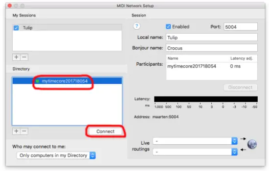
In case the TimeCore does not automatically become visible in the Directory listing then it is possible to add it manually. Click on the + button underneath the Directory section.
You are free to give it any name you like. The Host field should contain the TimeCore’s IP address. The Port field should be 65180. On Windows the host and port are combined, separated by a ’:’ character (e.g. 192.168.1.10:65180).
vManager
A free-of-charge software tool called vManager has been developed to manage the devices. vManager allows for:
- Setup the IP address, subnet mask, router and DHCP
- Backup and restore the device’s internal data and settings
- Perform firmware upgrades
- Identify a specific device (in a multi device set-up) by blinking its LED
- Revert to factory defaults

The following section explain the buttons in the vManager, as seen in figure 10.1.
10.1Backup
Backups of all the programming data inside the device can be made. This backup file (an XML) is saved on the computer’s hard-disk and can be easily transferred via e-mail or USB stick. The data of the backup can be restored via the Restore button.
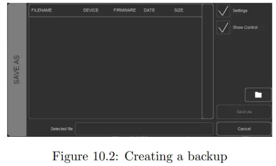
Apps distributed by app stores are not allowed to access files outside this designated location. It is important to know where vManager is storing its files, in case you wish transfer a backup file to memory stick or dropbox.
The designated file location differs per operating system and is likely to be a long and obscure path. For this reason, vManager provides you with a shortcut to the correct file location. A Folder button can be found in the file related dialogs. Clicking this button will open a file browser at appropriate folder.
10.2Upgrade Firmware
To upgrade the firmware, first select the device and press the Upgrade Firmware button. The dialogue allows for selecting from the list of firmware versions available.
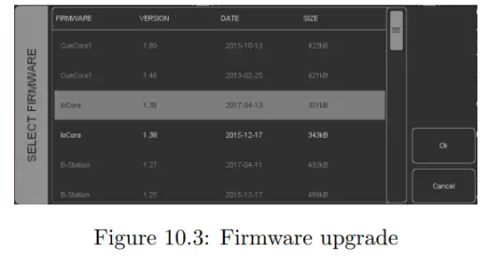
Warning: Make sure the power to the device is not interrupted during the upgrade process.
10.3Set Date & Time
The computer’s date and time can be quickly copied to the unit by selecting a device and clicking the Set Date & Time button. Not all Visual Productions devices feature an internal real-time clock. The TimeCore does not have such a RTC.
10.4Blink
The device’s LED can be set to Blink fast for identifying the particular unit amongst multiple devices. The blinking is enabled by double-clicking on a device in the Devices list or by selecting a device and then clicking the Blink button.
10.5Factory Defaults
All the user data like cues, tracks and actions are stored in the on-board flash memory. They will be completely erased and all settings will reverted to their defaults by pressing the Factory Defaults button. This action does not affect the device’s IP settings.
10.6Reboot
The Reboot button allows you to remotely restart the device. This is useful for testing the unit’s behaviour after a power-cycle.
10.7Installing vManager
The vManager app is available on a wide range of operating systems, both mobile and desktop.
The softwares is distributed through app-stores to take advantage of receiving future software updates automatically.
10.7.1iOS
vManager can be downloaded from the Apple iOS app-store at https://itunes.apple.com/us/app/vman/id1133961541.
10.7.2Android
vManager can be found on the Google Play store at https://play.google.com/store/apps/details?id=org.visualproductions.manager.
Android 5.0 or higher is required.
10.7.3Windows
Visit the Microsoft store at https://www.microsoft.com/en-us/p/vmanager/9nblggh4s758.
Windows 10 is required.
10.7.4macOS
Visit the Apple macOS app store at https://apps.apple.com/us/app/vmanager/id1074004019.
macOS 11.3 is recommended.
10.7.5Ubuntu
You can acquire the vManager from Snapcraft at https://snapcraft.io/vmanager.
Alternatively, it can be installed by using the command-line:
snap find vmanager
snap install vmanager
To update the apps later on via the command-line type: snap refresh vmanager
Ubuntu 22.04 LTS is recommended. The software is only available for the amd64 architecture.
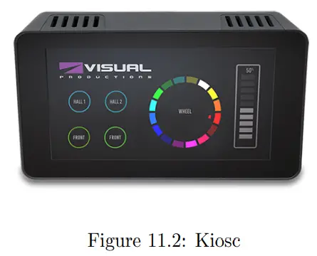
Kiosc
Kiosc is an application for creating custom touch screen user-interfaces for the range of lighting controllers from Visual Productions. Kiosc is designed to have no editing capability, making it a fool-proof interface that can safely be presented to non-technical operators.
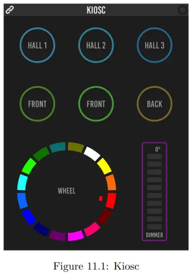
Kiosc is the ideal way to remote control our solid-state lighting controllers like CueluxPro, CueCore1, CueCore2, QuadCore, IoCore1, IoCore2, LPU-2, DaliCore, B-Station1 and the TimeCore. Kiosc enables you to choose scenes or presets, set intensity levels or choose RGB colours.
You can also use it to control third-party AV equipment. Kiosc speaks OSC, UDP and TCP.
Kiosc is available as software app and as a physical product. The hardware version of Kiosc is a wall-mount 7” touch screen with Kiosc pre-installed. It is powered by PoE and requires only a RJ-45 connection.
 Please read the Kiosc manual, available from https://www.visualproductions.nl/downloads for more details.
Appendices
Templates
This appendix discusses the templates provided in the Show Control page.
| Template | Description |
| Buttons ->timecode | Left push-button will start/stop. Right push-button will reset timecode. |
| Timecode state ->display | Timecode events like start, pause and stop will printed on the display. |
Trigger Types
The following tables list the different types of triggers that can be used in the CueluxPro. The different types are accompanied with values and flanks.
B.1Button
Two push-buttons at the front of the unit.
| Trigger Type | Trigger Value | Flank | Description |
| Button | Button number | Change | Button state changes |
| Button | Button number | Down | Button is depressed |
| Button | Button number | Up | Button is released |
| Short press | Button number | – | Button is depressed momentary |
| Long press | Button number | – | Button is depressed for long time |
B.2MIDI
| Trigger Type | Trigger Value | Flank | Description |
| Message | Address | Change | Receive a message that matches the address |
| Message | Address | Down | Receive a message that matches the address and the value non-zero |
| Message | Address | Up | Receive a message that matches the address and the value is zero |
| Receiving | – | – | Receive any message |
MIDI address can be any note-on, note-off, control-change, program-change and machine-control.
B.3RTP-MIDI
| Trigger Type | Trigger Value | Flank | Description |
| Message | Address | Change | Receive a message that matches the address |
| Message | Address | Down | Receive a message that matches the address and the value non-zero |
| Message | Address | Up | Receive a message that matches the address and the value is zero |
| Receiving | – | – | Receive any message |
MIDI address can be any note-on, note-off, control-change, program-change and machine-control.
B.4UDP
| Trigger Type | Trigger Value | Flank | Description |
| Message | String | – | Receive a message that matches the trigger-value |
| Receiving | – | – | Receive any message |
The user can define his own string as the trigger value of a message. Please note that this string has a maximum length of 31 characters.
| B.5 | TCP | |||
|
Trigger Type |
Trigger Value |
Flank |
Description |
|
| Message | String | – | Receive a message that matches the trigger-value | |
| Receiving | – | – | Receive any message | |
The user can define his own string as the trigger value of a message. Please note that this string has a maximum length of 31 characters.
| B.6 | OSC | |||
|
Trigger Type |
Trigger Value |
Flank |
Description |
|
| Message | URI | Change | Receive a message that matches the URI | |
| Message | URI | Down | Receive a message that matches the URI and the value non-zero | |
| Message | URI | Up | Receive a message that matches the URI and the value is zero | |
| Receiving | – | – | Receive any message | |
The user can define his own URI as the trigger value of a message, however, the OSC specification dictate this string must start with a ’/’ sign. Please note that this string has a maximum length of 31 characters, including the ’/’.
B.7Art-Net
| Trigger Type | Trigger Value | Flank | Description |
| Channel | DMX address | Change | Channel changes |
| Channel | DMX address | Down | Channel becomes non-zero |
| Channel | DMX address | Up | Channel becomes zero |
| UniverseA | – | – | A DMX level change in the universe |
| Receiving | – | Change | Start receiving or loose Art-Net signal |
| Receiving | – | Down | Lost Art-Net signal |
| Receiving | – | Up | Start receiving Art-Net signal |
B.8sACN
| Trigger Type | Trigger Value | Flank | Description |
| Channel | DMX address | Change | Channel changes |
| Channel | DMX address | Down | Channel becomes non-zero |
| Channel | DMX address | Up | Channel becomes zero |
| UniverseA | – | – | A DMX level change in the universe |
| Receiving | – | Change | Start receiving or loose sACN signal |
| Receiving | – | Down | Lost sACN signal |
| Receiving | – | Up | Start receiving sACN signal |
B.9Timecode
| Trigger Type | Trigger Value | Flank | Description |
| Timecode | Frame | – | Incoming timecode frame reached |
| Playing | – | Change | Playing state changed |
| Playing | – | Play | Timecode started |
| Playing | – | Not play | Timecode stopped |
| Paused | – | Change | Paused state changed |
| Paused | – | Pause | Timecode halted |
| Paused | – | Not pause | Timecode resumed |
| Stopped | – | Change | Stopped state changed |
| Stopped | – | Stop | Timecode stopped |
| Stopped | – | Not stop | Timecode started |
| Receiving SMPTE | – | Change | Receiving changed |
| Receiving SMPTE | – | Start | Start receiving |
| Receiving SMPTE | – | Stop | No longer receiving |
| Receiving MTC | – | Change | Receiving changed |
| Receiving MTC | – | Start | Start receiving |
| Receiving MTC | – | Stop | No longer receiving |
| Receiving RTP-MTC | – | Change | Receiving changed |
| Receiving RTP-MTC | – | Start | Start receiving |
| Receiving RTP-MTC | – | Stop | No longer receiving |
| Receiving Art-Net timecode | – | Change | Receiving changed |
| Receiving Art-Net timecode | – | Start | Start receiving |
| Receiving Art-Net timecode | – | Stop | No longer receiving |
B.10Kiosc
| Trigger Type | Trigger Value | Flank | Description |
| – | – | Change | Button/Fader goes up or down |
| – | – | Down | Button is pressed |
| – | – | Up | Button is released |
When editing the Kiosc actionlist it will be possible to add different kind of actions such as Button, Fader and Colour Picker. These elements will be displayed in the Kiosc app which is available from Visual Productions.
B.11Randomizer
| Trigger Type | Trigger Value | Flank | Description |
| Result | – | – | The Randomizer made a new value |
| Specific Value | Number in the range of [0,255] | – | The Randomizer made a value that matches |
B.12 System
| Trigger Type | Trigger Value | Flank | Description |
| Startup | – | – | The IoCore2 has been power up |
| Network Connection | – | Change | Network connection established or lost |
| Network Connection | – | Stop | Network connection lost |
| Network Connection | – | Start | Network connection established |
| ReleasedByMaster | – | Change | Master (e.g. CueluxPro) released or obtained connection |
| ReleasedByMaster | – | Stop | Master released connection |
| ReleasedByMaster | – | Start | Master obtained connection |
B.13Variable
| Trigger Type | Trigger Value | Flank | Description |
| Channel | Variable Index | – | The specified variable changes |
| Variable 1 | Number [0,255] | Change | Variable 1 becomes = or # to the value |
| Variable 1 | Number [0,255] | Down | Variable 1 becomes = to the value |
| Variable 1 | Number [0,255] | Up | Variable 1 becomes # to the value |
| Variable 2 | Number [0,255] | Change | Variable 2 becomes = or # to the value |
| Variable 2 | Number [0,255] | Down | Variable 2 becomes = to the value |
| Variable 2 | Number [0,255] | Up | Variable 2 becomes # to the value |
| Variable 3 | Number [0,255] | Change | Variable 3 becomes = or # to the value |
| Variable 3 | Number [0,255] | Down | Variable 3 becomes = to the value |
| Variable 3 | Number [0,255] | Up | Variable 3 becomes # to the value |
| Variable 4 | Number [0,255] | Change | Variable 4 becomes = or # to the value |
| Variable 4 | Number [0,255] | Down | Variable 4 becomes = to the value |
| Variable 4 | Number [0,255] | Up | Variable 4 becomes # to the value |
| Variable 5 | Number [0,255] | Change | Variable 5 becomes = or # to the value |
| Variable 5 | Number [0,255] | Down | Variable 5 becomes = to the value |
| Variable 5 | Number [0,255] | Up | Variable 5 becomes # to the value |
| Variable 6 | Number [0,255] | Change | Variable 6 becomes = or # to the value |
| Variable 6 | Number [0,255] | Down | Variable 6 becomes = to the value |
| Variable 6 | Number [0,255] | Up | Variable 6 becomes # to the value |
| Variable 7 | Number [0,255] | Change | Variable 7 becomes = or # to the value |
| Variable 7 | Number [0,255] | Down | Variable 7 becomes = to the value |
| Variable 7 | Number [0,255] | Up | Variable 7 becomes # to the value |
| Variable 8 | Number [0,255] | Change | Variable 8 becomes = or # to the value |
| Variable 8 | Number [0,255] | Down | Variable 8 becomes = to the value |
| Variable 8 | Number [0,255] | Up | Variable 8 becomes # to the value |
B.14Timer
| Trigger Type | Trigger Value | Flank | Description |
| – | Timer Index | Change | The timer starts or stops |
| – | Timer Index | Stop | The timer stops |
| – | Timer Index | Start | The timer starts |
B.15Actionlist
| Trigger Type | Trigger Value | Flank | Description |
| – | Actionlist Index | Change | Enabled checkbox has changed |
| – | Actionlist Index | Disabled | Checkbox has been disabled |
| – | Actionlist Index | Enabled | Checkbox has been enabled |
B.16User List (1-4)
User lists have no triggers. Actions inside user lists can only be activated by other actions through ’Action’ task with the ’Link’ feature.
Task Types
Tasks allow you to automate the functionality in the IoCore2. All this functionality is categorized in task-types. This appendix provides a listing of the various task-types. The tables present an overview of all available features and functions per task-type.
C.1Action
Trigger another action.
| Feature | Function | Parameter 1 | Parameter 2 |
| Link | Set | Action | – |
C.2Actionlist
Manipulate an actionlist.
| Feature | Function | Parameter 1 | Parameter 2 |
| Enable | Set | Action-list | On or Off |
| Enable | Toggle | Action-list | – |
| Enable | Control | Action-list | – |
| Enable | Inverted Control | Action-list | – |
C.3Button
Force the Button actions to be triggered.
| Feature | Function | Parameter 1 | Parameter 2 |
| Refresh | Set | – | – |
C.4DMX
Manipulate the DMX levels. These are the levels that can also be send out via Art-Net or sACN.
| Feature | Function | Parameter 1 | Parameter 2 |
| Universe | Control HTP | Universe # | – |
| Universe | Control LTP | Universe # | – |
| Universe | Control Priority | Universe # | – |
| Universe | Clear | Universe # | – |
| Channel | Set | DMX Channel | DMX Value |
| Channel | Toggle | DMX Channel | – |
| Channel | Control | DMX Channel | – |
| Channel | Inverted Control | DMX Channel | – |
| Channel | Decrement | DMX Channel | – |
| Channel | Increment | DMX Channel | – |
| Bump | Set | DMX Channel | DMX Value |
| Bump | Control | DMX Channel | – |
| Clear | Set | – | – |
| RGB | Set | DMX Address | RGB Colour Value |
| RGB | Control | DMX Address | – |
| RGBA | Control | DMX Address | – |
| XY | Control | DMX Address | – |
| XxYy | Control | DMX Address | – |
C.5MIDI
Send an MIDI message.
| Feature | Function | Parameter 1 | Parameter 2 |
| Send | Set | MIDI Address | MIDI Value |
| Send | Control | MIDI Address | – |
C.6MMC
Send an MMC (MIDI Machine Control) message via the MIDI port.
| Feature | Function | Parameter 1 | Parameter 2 |
| Send | Start | MIDI Channel | – |
| Send | Stop | MIDI Channel | – |
| Send | Restart | MIDI Channel | – |
| Send | Pause | MIDI Channel | – |
| Send | Record | MIDI Channel | – |
| Send | Deferred Play | MIDI Channel | – |
| Send | Record Exit | MIDI Channel | – |
| Send | Record Pause | MIDI Channel | – |
| Send | Eject | MIDI Channel | – |
| Send | Chase | MIDI Channel | – |
| Send | Fast Forward | MIDI Channel | – |
| Send | Rewind | MIDI Channel | – |
| Send | Goto | MIDI Channel | Time |
C.7MSC
Send an MSC (MIDI Show Control) message via the MIDI port.
| Feature | Function | Parameter 1 | Parameter 2 |
| Send | Set | Control Number | Control Value |
| Send | Start | Q Number | Q List |
| Send | Stop | Q Number | Q List |
| Send | Resume | Q Number | Q List |
| Send | Load | Q Number | Q List |
| Send | Fire | – | – |
| Send | All Off | – | – |
| Send | Restore | – | – |
| Send | Reset | – | – |
| Send | Go Off | Q Number | Q List |
C.8RTP-MIDI
Send an MIDI message via RTP-MIDI.
| Feature | Function | Parameter 1 | Parameter 2 |
| Send | Set | MIDI Address | MIDI Value |
| Send | Control | MIDI Address | – |
C.9RTP-MMC
Send an MMC (MIDI Machine Control) message via RTP-MIDI.
| Feature | Function | Parameter 1 | Parameter 2 |
| Send | Start | MIDI Channel | – |
| Send | Stop | MIDI Channel | – |
| Send | Restart | MIDI Channel | – |
| Send | Pause | MIDI Channel | – |
| Send | Record | MIDI Channel | – |
| Send | Deferred Play | MIDI Channel | – |
| Send | Record Exit | MIDI Channel | – |
| Send | Record Pause | MIDI Channel | – |
| Send | Eject | MIDI Channel | – |
| Send | Chase | MIDI Channel | – |
| Send | Fast Forward | MIDI Channel | – |
| Send | Rewind | MIDI Channel | – |
| Send | Goto | MIDI Channel | Time |
C.10OSC
Send an OSC message via the network. The OSC recipients are specified in the Settings page.
| Feature | Function | Parameter 1 | Parameter 2 |
| Send Float | Set | URI | floating point number |
| Send Float | Control | URI | – |
| Send Unsigned | Set | URI | positive number |
| Send Unsigned | Control | URI | – |
| Send Bool | Set | URI | true or false |
| Send Bool | Control | URI | – |
| Send String | Set | URI | String of characters |
| Send String | Control | URI | – |
| Send Colour | Set | URI | RGB colour |
| Send Colour | Control | URI | – |
Please note that string in parameter 1 has a maximum length of 25 characters, including the compulsory leading ’/’ sign.
C.11Randomiser
Trigger the Randomizer to generate a new random number.
| Feature | Function | Parameter 1 | Parameter 2 |
| Refresh | Set | Minimum value | Maximum value |
C.12System
Miscellaneous tasks.
| Feature | Function | Parameter 1 | Parameter 2 |
| Blink | Set | On or Off | – |
| Blink | Toggle | – | – |
| Blink | Control | – | – |
C.13Timecode
Control timecode related functions.
| Feature | Function | Parameter 1 | Parameter 2 |
| Playstate | Start | – | – |
| Playstate | Stop | – | – |
| Playstate | Restart | – | – |
| Playstate | Pause | – | – |
| Playstate | Toggle Start Pause | – | – |
| Playstate | Toggle Start Stop | – | – |
| Time | Set | Frame | – |
| Source | Set | Source | – |
| Source | Toggle | Source | Source |
| Source | Increment | – | – |
| Autonoom Pause | Set | On/Off | – |
| Enable | Set | Source | On/Off |
C.14Timer
Manipulate on of the four internal timers.
| Feature | Function | Parameter 1 | Parameter 2 |
| Playstate | Start | Timer # | – |
| Playstate | Stop | Timer # | – |
| Playstate | Restart | Timer # | – |
| Time | Set | Timer # | Time |
C.15UDP
Send an UDP message via the network. Specify the recipient in Parameter 2.
For example ”192.168.1.11:7000”.
| Feature | Function | Parameter 1 | Parameter 2 |
| Send Float | Set | floating point number | IP address & port |
| Send Float | Control | – | IP address & port |
| Send Unsigned | Set | positive number | IP address & port |
| Send Unsigned | Control | – | IP address & port |
| Send Bool | Set | true or false | IP address & port |
| Send Bool | Control | – | IP address & port |
| Send String | Set | text string | IP address & port |
| Send String | Control | – | IP address & port |
| Send String Hex | Set | hex string | IP address & port |
| Send String Hex | Control | String | IP address & port |
| Wake On Lan | Set | MAC Address | IP address & port |
Please note that string in parameter 1 has a maximum length of 25 characters.
The Send Bytes features allows for sending ASCII codes. For example, in order to send the string ’Visual’ followed by a line feed parameter 1 should be ’56697375616C0A’.
When using the Wake On Lan feature parameter 1 should contain the MAC Address of system’s NIC (Network Interface Controller) you wish to wake up.
The recommended value for parameter 2 is 255.255.255.255:7. This broadcasts the message to the whole network at port 7 which is most commonly used for Wake On Lan.
C.16Variable
Manipulate one of the eight variables.
| Feature | Function | Parameter 1 | Parameter 2 |
| Set Value | Set | Variable [1,8] | Value [0,255] |
| Set Value | Toggle | Variable [1,8] | Value [0,255] |
| Set Value | Control | Variable [1,8] | – |
| Set Value | Inverted Control | Variable [1,8] | – |
| Set Value | Decrement | Variable [1,8] | – |
| Set Value | Increment | Variable [1,8] | – |
| Set Value | Continuous Decrement | Variable [1,8] | Delta [1,255] |
| Set Value | Continuous Increment | Variable [1,8] | Delta [1,255] |
| Set Value | Stop Continuous | Variable [1,8] | – |
| Set Value | Control Scaled | Variable [1,8] | Percentage [0%,100%] |
| Set Value | Control Offset | Variable [1,8] | Offset [0,255] |
| Refresh | Set | Variable [1,8] | – |
| Single Dimmer | Control | Variable # | Delta |
Variables are further explained on page 29.
The Single Dimmer feature is used to increase or decrease a level by using only one switch. When controlling this task via GPI action, then closing the GPI will increase or decrease the level. Opening the GPI port will freeze on the current level. This feature is useful for controlling an intensity will just one button.
API
The TimeCore is pre-programmed to make its internal functionality available via OSC and UDP. There is a simple API implemented for each protocol. Notwithstanding these API’s, it is possible to create your own OSC and UDP implementation in the Show Control page.
D.1OSC
The following table uses actionlist #1 as an example. The number ’1’ can be replaced by any number in the range of [1,8]. The table also uses action #2 as an example. The number ’1’ can be replaced by any number in the range of [1,48].
| URI | Parameter | Description |
| /core/al/1/2/execute | bool/float/integer | Execute action #2 inside action list #1 |
| /core/al/1/enable | bool | Set the ’enable’ checkbox for action list #1 |
| The following table shows how to manipulate the internal timecode. | ||
| URI | Parameter | Description |
| /core/tc/start | – | Start timecode |
| /core/tc/stop | – | Stop timecode |
| /core/tc/restart | – | Restart timecode |
| /core/tc/pause | – | Pause timecode |
| /core/tc/set | time-string | Set the timecode frame at the specified string. For example ”23:59:59.24” |
The following table uses timer #1 as an example. The number ’1’ can be replaced by any number in the range of [1,4].
| URI | Parameter | Description |
| /core/tm/1/start | – | Start timer #1 |
| /core/tm/1/stop | – | Stop timer #1 |
| /core/tm/1/restart | – | Restart timer #1 |
| /core/tm/1/pause | – | Pause timer #1 |
| /core/tm/1/set | time-string | Set timer #1 at the time-string |
The following table uses variable #1 as an example. The number ’1’ can be replaced by any number in the range of [1,8].
| URI | Parameter | Description |
| /core/va/1/set | integer | Set the value of variable #1 |
| /core/va/1/refresh | – | Refresh variable #1; a trigger will be generated as if the variable changed value |
| /core/va/refresh | – | Refresh all variables; triggers will be generated |
The following table shows how to active miscellaneous functions.
| URI | Parameter | Description |
| /core/blink | – | Momentarily flashes the TimeCore’s LED |
D.2TCP & UDP
The following table uses actionlist #1 as an example. The number ’1’ can be replaced by any number in the range of [1,8]. The table also uses action #2 as an example. The number ’1’ can be replaced by any number in the range of [1,48].
| String | Description |
| core-al-1-1-execute=<arg> | Execute action #2 inside action list #1 |
| core-al-1-enable=<bool> | Set the ’enable’ checkbox for action list #1 |
The following table shows how to manipulate the internal timecode.
| String | Description |
| core-tc-start | Start timecode |
| core-tc-stop | Stop timecode |
| core-tc-restart | Restart timecode |
| core-tc-pause | Pause timecode |
| core-tc-set=<text> | Set the timecode frame at the specified string. For example ”23:59:59.24” |
The following table uses timer #1 as an example. The number ’1’ can be replaced by any number in the range of [1,4].
| String | Description |
| core-tm-1-start | Start timer #1 |
| core-tm-1-stop | Stop timer #1 |
| core-tm-1-restart | Restart timer #1 |
| core-tm-1-pause | Pause timer #1 |
| core-tm-1-set=<text> | Set timer #1 at the time-string |
The following table uses variable #1 as an example. The number ’1’ can be replaced by any number in the range of [1,8].
| String | Description |
| core-va-1-set=<integer> | Set the value of variable #1 |
| core-va-1-refresh | Refresh variable #1; a trigger will be generated as if the variable changed value |
| core-va-refresh | Refresh all variables; triggers will be generated |
The following table shows how to active miscellaneous functions.
| String | Description |
| core-blink | Momentarily flashes the TimeCore’s LED |
D.3Feedback
The TimeCore is able to send feedback to external equipment using its API, so called ’clients’. The TimeCore keeps a memory of the last four OSC clients and last four UDP clients. The clients will automatically receive updates on several playback related state changes. Below is a table listing the messages the TimeCore will send back to its clients. The hello command is ideal for polling the device; it allows you to verify that the TimeCore is online at the IP address and port that you expect. A power-cycle will clear the internal client lists. Send /core/goodbye or core-goodbye to explicitly be removed from the client list. Consider programming custom action in the show control when additional feed- back functionality is required.
D.4Peventing a feedback loop
Feedback is automatically send to a device which uses the OSC or UDP API. If the external device is also a Visual Productions unit then the feedback message could be interpreted by the external unit a new command. This can result in another feedback message being generated. An endless stream of feedback messages can stall the units involved. This feedback loop can be prevented by assign a unique label the device’s API prefix. This setting is discussed on page 8.1.
![]() QSD 34
QSD 34
The SCC and IAS Accreditation Symbols are official symbols of the respective accreditation bodies, used under license
81 Kelfield St., Unit 8, Toronto, ON, M9W 5A3, Canada Tel: 416-241-8857; Fax: 416-241-0682
www.qps.ca
Rev 05
![]()
![]()
Documents / Resources
 |
VISUAL PRODUCTIONS TimeCore Time Code Display [pdf] Instruction Manual TimeCore Time Code Display, TimeCore, Time Code Display, Code Display, Display |