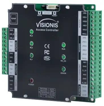
VISIONIS VIS-AXESS-2D-ETL-PCB Two-Door Network Access Control PCB Board Controller
Product Information
The device is designed to operate on a DC 12V working voltage with a non-loaded working current. It is built to provide efficient performance and functionality for various applications.
Product Usage Instructions
Power Connection
Ensure to connect the device to a DC power source with a voltage output of 12V. Use the appropriate cables and connectors to establish a secure connection.
Operating the Device
Once the power connection is established, switch on the device using the designated power button. Follow the specific instructions related to the device’s functionality or settings.
Maintenance
Regularly check the power source and connections to ensure the proper functioning of the device. Keep the device clean and free from dust or debris that may affect its performance.
Device Parameter
- Working Voltage: DC 12V
- Working Current: Non-loaded <200mA
- Working Temperature: -20°C – 50°C (-4°F – 122°F) Working Humidity: 10° – 90°
- Power Consumption: <3W
- Size: 123 x 120 x 20mm (4.84 x 4.72 x 0.79in.) Communication Mode: TCP/IP
- Communication Rate: 10/100M (TCP/IP) Extension Communication: RS485
- User Capacity: 20.000
- UUserCapacity: 70.000 records
- Max. Doors: 2
- Dry Contact Input: 6
- Dry Contact Output: 3
- Access Group: 200 Groups
- Default IP Address: 192.168.0.245
- Default Communication Password: NULL
IMPORTANT: These access control panels (Version 2.0) are only compatible with access control panels (Version 2.0) and with the Titan VSAxess software. They are not compatible with access control panels (Version 1.0) nor with VSAxess software.
Basic Function
- FiThe first and open
- Multi-card open
- Anti-passback
- Multi-door interlock
- Card, password, card+password, card or password open mode
- Different times different open mode
- Transmission encryption setup
- Self-checking function
- Remote control
- Wiegand format can be self-defined
- Add card without software
- Multi-channel connection(max. 3 channels)
- Real-time events active or passive upload
- Arm/disarm by card
- Arm/disarm by software
- Relieve alarm by software
- Multi-event linkage alarm
- One event related to multi-relay trigger
- Alarm delay turn off
- Capacity can be expanded
- Self-defined door lock relay
- Self-defined control door quantity
- Door latch mode
- Active door normal open mode by card
- Timed automatic normal open mode
- Timed invalid for the exit button
- Normal open time
- Normal open holiday forbidden schedule
- Access schedule
- Forbid access holiday schedule
- Door lock delay setup
- Access group set up
- Threaten code setup
- Force open/close door
- Open door by software
- Relieve normalopeningn by card
- Relieve card and card valid date setup
- Expand RS485 communication
- Real-time monitoring of door and relay state
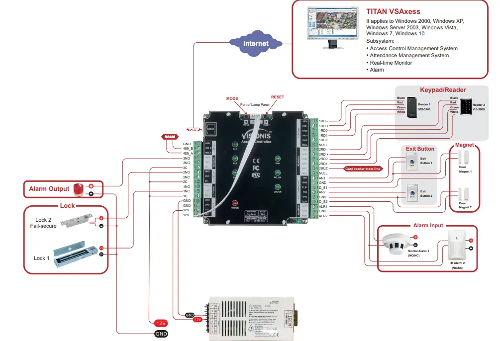
Wiring Introduction
| Wiring Position | Wire Model | Remark |
| Power Supply – Access Controller | RVV2*1.0 | Distance < 100M |
| Access Controller – Reader | RVV4*0.5 | Distance 60M, max. can not be over 100M. |
| Access Controller – Electric Lock | RVV4*1.0
(Door-magnet feedback) |
Distance < 150M |
| Access Controller – Exit Button | RVV2*0.5 | Distance < 200M |
| Access Controller – IR Alarm | RVV2*1.0 | Distance < 200M |
| Access Controller – Sound-light Alarm | RVV2*1.0 | Distance < 150M |
| RS485 Communication Cable | RVVP2*1.0 | Distance < 1000M, shield layer connected to ground |
| TCP/IP Communication Cable | CAT-5 | Distance < 100M |
Disclaimer
The document provides information according to product specifications. Visionis does not undertake any type of guarantee, express or implied warranties, including any implied merchantability, specific purposes, or infringement. The information in the document is changed without prior notice. Visionis and its associated sales agents special statement do not assume the result of the use of Visionis equipment of any direct, indirect, special, in general, by chance, inevitably, punitive damages. For any user’s improper operation or use of the environment problem caused by direct or indirect losses, the user pays full responsibility, and equipment manufacturers and related sales agents do not undertake any responsibility.
Connection
| I/O | Device | Standard | Quantity | Setup |
| Input | Reader | Wiegand 26-40 | 2 | as function |
| Output | Electric Lock | Switch Signal | 1/2 | as doors |
| Input | Door-magnet | Switch Signal | 1/2 | Support |
| Output | Sound-light alarm | Switch Signal | 1/2 | |
| Input | IR Sensor/Smoke Sensor/Others | Switch Signal | 2 | |
| Input | Exit button | Switch Signal | 1/2 | Support |
| Input | RS485 device | Communication | 1 |
LED&Button Instruction
| LED | RL1 | RL2 | RL3 |
| One-door | Lock1 | Magnet Alarm1 | Alarm Output1 |
| Two-door | Lock1 | Lock2 | Magnet Alarm1 |
- Power: 12V power LED
- RUN: Device run LED
- RDOK: Read card status LED
- 2DOOR: The status LED of 2 doors
- RDOK + RUN: Device enters online upgrade mode.
- RESET Key: It is used to rebootthe the device and clear the communication password. After powering off, power on the device
Wiring Diagram of Access Controller
Quick Start
Search Controller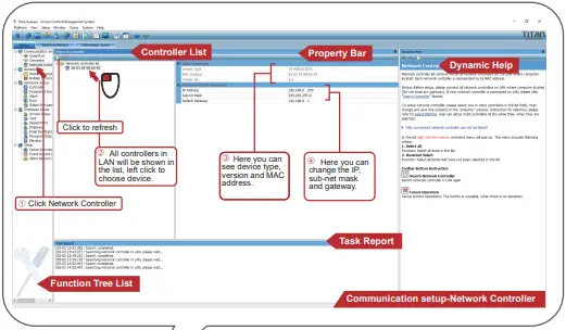 Add Controller
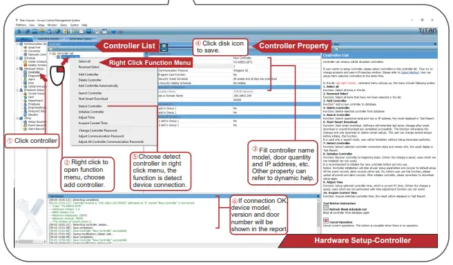 Notice:
- The controller IP must be the same as you set.
- CThe controller model must be the same as the device type. You can detect the controller and check the device type in the task report.
- Usually, we can use the ping command to test the device’s physical connection.
- Controller Address is only valid when using MS series controller or TCP/IP to RS485 connector, otherwise, the default is 0.
- The wrong time may have no access and can correct the access record. Please adjust the time.
- Initializing the controller will clear the device records, please make sure the records are saved.
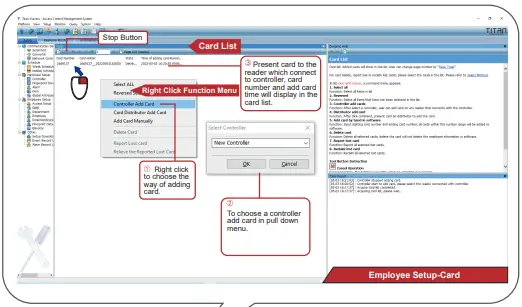
Add Card
 Notice:
- Three ways to add a card, a card distributor adds a card, a controller adds a card, and adds a card manually. Card distributor adds card need to choose our card distributor.
- The same card can only be added once.
- Please note that deleting the card will clear the card related to the employee.
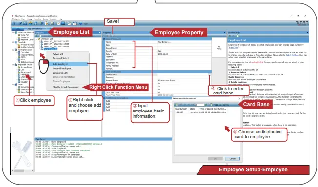
4. Add Employee
 Notice:
- If there are employees with the same name, you can separate them by code. The code is unique.
- The card number is decimal.
- The default administrator access group can pass anywhere anytime, it is the top authority.
- Each employee can access it with a separate 6-digit password.
- IImportfrom Excel can quickly register employees.
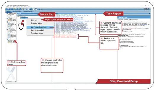
Download Setup
 Notice:
- Three download setup ways: Download setup, download all setups, and smart download. Download setup refers to the current device, download all setups and smart download refers to all devices. Smart download only downloads updated content. The other two are to download all setups.
- When adopting smart download and downloading all setups, if there is a device offline, it will prompt an error.
- The default administrator access group can pass anywhere anytime, it is the top authority.
Notice:
- The search function is only valid in the same LAN, as adopting the UDP communication protocol, across the gateway will forbid communication.
- When connecting the network cable to the device, the Ethernet port green light is on, yellow light flashes.
- Please note that the IP address can not be the same.
- Domain names can be used in the software.
Notice:
Once installed the Titan Vsaxess Login information is: Username: Administrator Password:
There is no default Password. Just click OK and you can log in. You can set a Password under “Platform” and “Change password”.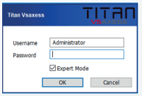
The manual is a quick stafo thethe r system, the user can refer to the software help file or other technical files for details.
Important Notices
- Power off when wiring.
- Power on when wiring the power supply output current must be 1.3 times bigger than thedevice’se work current.
- The lock should better use a separate power.
- All devices must be connected to a common GND.
- RS485 communication must use a hand-to-hand connection.
- Between different readers should have 10cm to avoid interference.
- As it is a currently weak system, strong and weak isolation must be done.
- The wiring of strong and weak should not be parallel and the distance at least 20cm.
- RS485 line should connect the cable shield to GND to avoid interference.
- When the RS485 line interfaces more devices, the user can add a 120Ω resistance between 485+ and 485- of the last device.
- The reader can not be installed on the metal directly.
FAQs
Q: What should I do if the device does not power on?
A: Check the power connection to ensure it is properly secured and the voltage output is correct. If the issue persists, contact customer support for further assistance.
Q: Can I use a power source with a different voltage?
A: No, it is recommended to only use a DC 12V power source as using a different voltage may damage the device and void the warranty.
Documents / Resources
 |
VISIONIS VIS-AXESS-2D-ETL-PCB Two Door Network Access Control PCB Board Controller [pdf] User Guide VIS-AXESS-2D-ETL-PCB, VS-AXESS-2D-ETL-PCB-version2, VIS-AXESS-2D-ETL-PCB Two Door Network Access Control PCB Board Controller, Two Door Network Access Control PCB Board Controller, Network Access Control PCB Board Controller, Control PCB Board Controller, Board Controller, Controller |