![]()
 Sổ tay hướng dẫn sử dụng lập trình viên CH341A (Phiên bản đèn màu)
CH341A Programmer Instructions
(Color Light Version v1.5, v1.6, v1.7 Universal)
2023/8/18 Contents Table of Contents
Giới thiệu về bộ lập trình CH341A
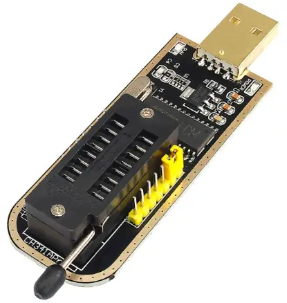
Our compact ch341a programmer is only 22mm*50mm in length and width, easy to carry around, with integrated level shifter circuitry, supporting 1.8v minimum. Based on the compact and convenient design considerations, so through the toggle switch K1 to change the voltage, can support 5v, 3.3v, 2.5v, 1.8v, also supports ttl output (minimum support 1.8v standard) It can be described as compact and multi-functional, burn 8-pin chip and not fall down the serial port brush, while integrated infrared code module. spi interface output support for low-voltage, cũng thông qua nút chuyển đổi K1 để đạt được.
Tải xuống phần mềm: http://198.11.174.230/ch341a-Software.zip
This is what our programmer looks like
Plug directly into the usb port and try to avoid grabbing space with other usb devices.
Meanwhile, in order to adapt to most of the 8-pin chips, we have also equipped with simple adapter boards for 25xx, 24xx, 93xx, 45xx and other packages, in order to fulfill the needs in one step. We will also design adapter boards for the packages you need later.
We have labeled the interface and voltage bật bảng, vì vậy bạn không còn phải lo lắng về việc không tìm thấy hướng dẫn nữa.
Differences between v1.5, v1.6 and v1.7:
*Locking Block 25xx, 24xx No Resistor Pull-Up and Down
*v1.6 Locking Block 25xx Partial Resistor Pull-Up
*v1.7 Locking Block 25xx partial resistor pull-up, 24xx partial resistor pull-down
Tuyên bố:
The ch341a programmer hardware is designed and developed by us and is copyrighted.
The software is open source or shareware and the copyright (authorship) belongs to them, please respect the fruits of their labor and thank them for their dedication and contribution to the programmer industry.
Phần cứng của lập trình viên
Thiết kế bộ lập trình tương đối nhỏ gọn, có thể cắm trực tiếp vào cổng USB để sử dụng, mỗi giao diện và chức năng jumper đều có hướng dẫn sử dụng trên bo mạch, hầu hết các trường hợp đều có thể hiểu mà không cần xem hướng dẫn. Bộ lập trình được tích hợp mạch dịch chuyển mức và hỗ trợ mức âm lượng tối thiểu.tage of 1.8v. Based on the compact and convenient design considerations, so through the toggle switch KI to change the voltage, can support 5v, 3.3v, 2.5v, 1.8v, also supports ttl output (minimum 1.8v low level) Directly support most of the 1.8v 24, 25 chips without the need for level shifter boards, such as w25q64fw, w25q128fw and so on. 1. Chip placement method
Please refer to the diagram below for placement of the chips, noting the orientation of the chips
Chúng tôi sử dụng đế khóa 16 chân, mỗi chân 8 chân sẽ thực hiện một loạt lần ghi chip, bo mạch đã đặt theo hướng logo. Chip 45xx và 93xx sử dụng đế giữ, nhưng bạn không thể đặt chip trực tiếp vào đế giữ khóa, vì nó sẽ làm cháy chip. Vui lòng lưu ý điều này, bạn chỉ có thể sử dụng bộ chuyển đổi đặc biệt mà chúng tôi cung cấp để thực hiện. Xin lưu ý rằng có hướng dẫn trên bo mạch chuyển đổi để đặt chip vào phần đế giữ đó.
2. Đầu ra voltagvà Vout
Xem ký hiệu K1 trong sơ đồ và hướng dẫn sử dụng cầu nối ở mặt sau của bộ lập trình. Đây là chip đọc/ghi và chân spi đầu ra voltage, tất cả thông qua nút chuyển đổi K1 để đạt được âm lượng khác nhautagvị trí công tắc chuyển đổi trở lại tương ứng với âm lượngtage nhận dạng
 The programmer K1 position is normally issued for 3.3v.
**Toggle switch K1 increases the voltage all the way from the latch to the usb port.
**Please adjust the voltage trước khi đốt chip để tránh cháy chip do vol caotage, công tắc K1 không thể hoạt động trong bộ lập trình khi đang bật nguồn, vui lòng rút phích cắm bộ lập trình ra để quay số rồi cắm lại!
The toggle position is shown below:
a) 1.8v toggle switch position reference
b) Tham chiếu vị trí công tắc bật tắt 2.5v
c) Tham chiếu vị trí công tắc bật tắt 3.3v (mặc định)
 d) Tham chiếu vị trí công tắc bật tắt 5v

3. spi output (programmer mode)
Programmer J1 pin numbering, with corresponding description on the back
Cài đặt mặc định của bộ lập trình là nối tắt chân 1-2 của đầu ra spi J1. Sau đây là danh sách các chức năng của chân đầu ra J1
| J1 | 112 | 3 | 4 | 5 | 6 | 7 | 8 | 9 | 10 | 11 | 12 |
| function ality | SPI/TTL | IR | 2 | TXD | CLK | 6 | DAWDLE | MISO | GND | vout | 5v |
Here we only use pin 6~ 11. Refer to entry 1 for the Vout voltage mô tả.
Through the spi interface to read and write chips on the board, please note that the wiring should not be too long, there will be interference or speed drop or can not recognize the chip, the reference line length of 10cm or so, depending on the circumstances of the set.
4. TTL output
Số chân J1 của lập trình viên được dán nhãn với mô tả tương ứng ở mặt sau. Mức ttl có thể nhận ra nhiều mức âm lượng khác nhautagchế độ e, được thực hiện bằng cách thiết lập Vout voltage của J2. Ví dụampVâng, nếu bạn cần mức 5v, chỉ cần nhảy Vout lên 5v; đối với mức 3.3v, Vout nhảy lên 3.3v; đối với mức 1.8v, Vout nhảy lên 1.8v. Chức năng này là chức năng cổng nối tiếp của bộ lập trình, đầu ra ở mức TTL, có thể được gắn trực tiếp vào giao tiếp cổng nối tiếp của CPU, tham chiếu jumper theo biểu đồ sau
 J1 pins 1 and 2 are unplugged from the jumper The following is a description of the function of J1
| J1 | 1 | 2 | 3 | 4 | 5 |
| chức năng | SPI/TTL | IR | ĐỒNG HỒ | TXD | |
When flashing, you can directly connect J1’s 4,
5, 10 will work 5, TTL self test
To test if the TTL interface is working properly, short J1 pins 4 and 5 as shown below. Available general-purpose serial port software to test whether the serial port can send and receive data, we here to provide a simple test tool, test multiple rates at a time to finish
The software is in the root directory of the package, please run “USB-TTL Detection.exe” and set your serial port number.
Nhấp vào bắt đầu để bắt đầu kiểm tra Nếu bạn nhận được thông báo NG, vui lòng kiểm tra xem vị trí bán khống có chính xác không.
6. Infrared code measurement
Using the ttl function of the programmer to realize infrared code measurement, together with the special code measurement software can realize the code measurement of remote control and other infrared devices.
Sau đây là mô tả chức năng của J1
| J1 | 1 | 2 | 3 | 4 | 5 |
| chức năng | SPI/TTL | IR | ĐỒNG HỒ | TXD | |
Here we need to short pin 3 and 4 of J1 to realize code measurement, and K1 should be switched to 3.3v or 5v at the same time. Run the “RC Analyzer Fix.exe” software in the package.  Select the serial port number of the 341 and open the serial port.
 Nhấn điều khiển từ xa để hiển thị mã đo lường, kèm theo lời nhắc giải mã. Nhớ nhấn để đóng cổng nối tiếp trước khi rút phích cắm bộ lập trình sau khi sử dụng.
Mô tả đèn màu
Colorful light version has 3 main colors Power red, plug in the usb is always on
Read/Write 24 Chip, Green, Flashes When Reading/Writing
Read/write 25, 93, 45 chips, blue, flashing mixed colors when reading/writing is colored
TTL is also flashing when brushing or testing.
IR code measurement, the light will also flash, but not so obvious, code measurement jump connection after plugging in the usb light will be on!
Sử dụng bảng mạch điều hợp đơn giản và khối ghi
1. Universal adapter plate
Universal 8pin adapter board can be used for 24xx, 25xx, but the sop16 pads on the board can only be used for 25 chips, and there is also a chip clip interface, please correspond to the pin wiring, the pin number is the same as the chip pin number.  Nếu bạn cần hàn các chân của ổ quayamp, vui lòng hàn các chân trước, nếu không chúng sẽ bị ghim bởi các chân khác, sau đó mới hàn các chân vào giá đỡ.
2. 93xx chip placement method diagram
The 93xx chips are read/written using Block 25, so you need to put the adapter board into that position. Please note that you cannot put the 93 chip directly into the locking seat, the pins do not correspond to each khác.
Ghi chú: The adapter board is only suitable for general-purpose 93 series chips, such as special chips such as br, you can not use the adapter board directly, you need to make your own according to the circuit diagram provided. Please contact the merchant or refer to the wiring diagram of asprogrammer software.
3. 45xx chip placement
The 45xx chip also reads and writes through the 25 holder, you cannot put the 45 chip directly into the locking holder, please use the adapter board. This chip has
There are two types of packages, long and short, the short one can be directly called out on the board, and the long one just needs to be soldered on the 1-pin side. Nếu bạn sử dụng các loại máy phát xung khác, xin lưu ý rằng hướng của chip phải giống với hướng của logo lập trình viên.
4. st95xxx series automotive memory chips
It is also possible to directly use the sop8 pad in the general-purpose sop adapter board and plug it directly into the programmer 25xx position. Because the chip does not support automatic search, you have to manually select the corresponding model to read and write. 5. KB901x class chip wiring diagram
Please use As Programmer, of course other software support is also available, here is just explain how to connect with this chip with our programmer.
kb9010/kb9012/kb9016/kb9018/kb9022 về cơ bản là gói LQFP128, do đó phương pháp nối dây về cơ bản là giống nhau. Chip pin diagram as above, each board layout are different, in the board brush wiring may also be different, it is best to correspond to the chip pins to find the best flying line point!
Flying line please try to shorten it to avoid interference, generally recommended at about 10cm kb9012 -> ch341a programmer
| kb901x foot number | Mô tả chức năng | Counterpart 25 | ch341 Programmer spi output J1 |
| 59 | EDI_CS | CS (RST) | 7 |
| 60 | EDI_CLK | SCK | 6 |
| 61 | EDI_DIN | DAWDLE | 8 |
| 62 | EDI_DO | MISO | 9 |
| 44 | TP_PLL_LOCK | GND | 10 |
| 33 | VCC | 3.3V | Chổi than trên bo mạch không được kết nối (11, cầu nối 3.3v) |
6, qfn8 adapter plate
The simple adapter board integrated qfn8 8mm * 6mm, 6mm * 5mm two packages of chips, in order to weld, the middle heat dissipation pad is not done, easy to disassemble, and at the same time lengthened pads, easy to direct soldering iron welding. The small white dot on the top is pin 1 of the chip, pay attention to it when soldering.
With this board soldering iron can be soldered, but remove it is best to use a hot air gun to blow down, otherwise it is easy to follow the bad pads
7, bga24 adapter board
This simple adapter plate can be applied to bga24 8mm*6mm 4*6 ball array, bga24 8mm*6mm 5*5 ball array at the same time, wlcsp16 ball, wclsp8 ball chip, wclsp8 directly soldered in the middle two columns can be.
Vì bo mạch này cần có súng nhiệt nên nó có lớp đồng Fu ở mặt sau và nhiệt sẽ làm đều các chip một chút.
8、bga24 8mm*6mm
Giá đỡ Flip-Flop mảng bi 4*6
Giá đỡ flip-flop làm bằng đầu dò tiện lợi hơn so với việc sử dụng tấm chuyển đổi đơn giản và rẻ hơn giá đỡ flip-flop chuyên nghiệp hơn 2/3, giá rẻ và tiện lợi, đồng thời là giá đỡ không thể thiếu để bảo trì. Cắm bga24 vào dip8 trực tiếp vào giá đỡ khóa của bộ lập trình 341 để sử dụng.
 Khi sử dụng, khuyến cáo nên rút phích cắm của bộ lập trình và đặt chip vào trước khi cắm vào cổng USB để đọc và ghi, tránh làm cháy chip hoặc bảo vệ cổng USB do đặt không đúng vị trí.
9, bga24 8mm*6mm
Giá đỡ Flip-Flop mảng bi 5*5
Giá đỡ flip-flop làm bằng đầu dò tiện lợi hơn so với việc sử dụng tấm chuyển đổi đơn giản và rẻ hơn giá đỡ flip-flop chuyên nghiệp hơn 2/3, giá rẻ và tiện lợi, đồng thời là giá đỡ không thể thiếu để bảo trì. Kết nối phổ biến bga24 với dip8, cũng có thể được sử dụng cho các lập trình viên khác
10. qfn8 8mm*6mm Flip-flop seat
Because the chip pad of qfn8 package is relatively small and close to the edge of the chip, it is difficult to design and the precision is quite high. Place the chip may need tweezers to put a good point, and at the same time with the hand to determine the elasticity of the pressure, and then cover the top cover, cover can not be used with brute force, if you can not completely cover, finger pressure resistance, please turn over to check whether the chip runs! 11. qfn8 6mm*5mm Flip-Top Stand
Because the chip pad of qfn8 package is relatively small and close to the edge of the chip, it is difficult to design and the precision is quite high. Place the chip may need tweezers to put a good point, and at the same time with the hand to determine the elasticity of the pressure, and then cover the top cover, cover can not be used with brute force, if you can not completely cover, finger pressure resistance, please turn over to check whether the chip runs! 12. 93xx adapter plate improved (optional)
There are many manufacturers of 93 series chips, the wiring is mostly the same, but the main difference lies in pins 6and 7. The adapter boards distributed are generally universal, but may not work for some chips.
Ví dụample, it can only be used in 16-bit mode, and st m93c46 which requires pin 7 to be grounded, etc. Others that I haven’t come across are not listed.
In order to be adapter board to adapt to a wider range, so the design of a more versatile adapter board, but the demand fotheir own soldering of different resistors to achieve!
The resistor will be soldered to R1R3 by default Chip pin 6, corresponding to the mark org R3R4 two resistors, R3 pull-up vcc for 16-bit mode, R4 pull-down GND for 8-bit mode chip pin 7, corresponding to the mark pre R1R2 two resistors, R1 pull-up vcc, R2 pull-down GND, this depends on the specific chip to determine, in some cases, R1 can not be soldered can also be used, 93sxx chips need to be soldered to the R2 to work!
After soldering the following picture 13. BR93xx adapter plate (optional)
Such as: br9010F, br93c46F, 93CS46F, etc. can not be used directly with the default 93xx adapter board, the chip may appear hot, so specifically designed for such chips an adapter board, please see http://www.diybcq.com/thread-145554-1-1.html
Theo mặc định, điện trở được hàn sẵn.
Điện trở nối đất kéo xuống cho chế độ 16 bit Chip types without F are soldered in the way shown above, and sop packages are soldered with u3 pads.
 Models with F, dip inserts need to be soldered as shown above to work, sop uses U3F pads.
Cài đặt trình điều khiển
Generally the programmer software zip package with driver, if your system is win7, may also automatically install the driver, if not installed, please install.
There are driver installation files for the most recent ch341 in the latest driver directory of the packet.
1. Programmer driver
Normal programmer mode uses a parallel driver, so please run the CH341PAR.EXE file để cài đặt nó.
 2. TTL serial port driver
If you are using the TTL method, then run the CH341SER.EXE file để cài đặt nó.
Phần mềm lập trình
Tuyên bố:
The ch341a programmer hardware is designed and developed by us and is copyrighted (copyrighted) by us.
The software is open source or shareware, the copyright (authorship) belongs to them, please respect the fruits of their labor and thank them for their contribution to the programmer industry.
The programmer we designed strives for versatility, so as long as the programmer software developed based on the ch341a chip can be used, depending on which one you are familiar with. Here we recommend using Asprogrammer, neo programmer and Maple Leaf Online to write software for ch341 usb programmer. For more software and resources please visit
1. Asprogrammer (diy programmer.com optimized version)
The original version of the open source software, the original designer for tifa, mã nguồn, the original post URL, thank him for his selfless efforts.
Sự tiến bộtagƯu điểm của phần mềm này là bạn có thể dễ dàng thực hiện việc bổ sung mô hình chip, đồng thời sử dụng trình lập trình của chúng tôi để đọc và ghi chip 93, 45, 95. Chỉ có thể sử dụng phần mềm này. Chúng tôi cung cấp phần mềm ở phiên bản gốc dựa trên việc tối ưu hóa, sửa đổi giao diện và chức năng nhắc nhở, phù hợp với thói quen sử dụng của mọi người, thao tác đơn giản hơn. Đồng thời, chúng tôi cũng có video hướng dẫn thao tác đọc và ghi chip trên máy. webtrang web cho mọi người học hỏi tham khảo. Các website also has source code download (http://www.diybcq.com/thread-144069-1-1.html) .
Các lập trình viên và phần mềm trên website will be updated in real time, please pay attention to the CH341A programmer
 Specific use of the package, please see the “3. Tutorial”, which has text tutorials and video tutorials program to add their own chip model please move to the webĐịa điểm:.
How to add chip model number to AsProgrammer software http://www.diybcq.com/thread-144126-1-1.html
Làm thế nào để tìm thông tin bạn cần từ hướng dẫn sử dụng http://www.diybcq.com/thread-144154-1-1.html
1.1 Hướng dẫn cách sử dụng asprogrammer
Because the original software is not very convenient to use, so we do in order to adapt to the habits of everyone to do the layout adjustment, at the same time will be the function of the iconization, both easy to use at a glance. The following is the software after our revision, and optimize some functions, make the software interface.
Nhanh hơn và dễ sử dụng hơn.
Mainly introduces the operation of the toolbar, the following is the toolbar function description, as long as your mouse over the corresponding buttons will be prompted, here in order to intuitively do the identification of the software interface
a)The save function is turned on.
Đây là chức năng thường dùng, về cơ bản chúng ta chỉ nhìn biểu tượng là biết, không giải thích chi tiết. ![]() Mở chỉ hỗ trợ bin file định dạng, vì vậy mở sẽ tự động lọc thùng rác files, tất nhiên bạn có thể chọn tất cả files
Mở chỉ hỗ trợ bin file định dạng, vì vậy mở sẽ tự động lọc thùng rác files, tất nhiên bạn có thể chọn tất cả files ![]() Lưu cũng được lưu dưới dạng thùng rác file, automatically add the .bin extension.
Lưu cũng được lưu dưới dạng thùng rác file, automatically add the .bin extension.
b)Chip Selection
Sau đây là các chức năng chung của lập trình viên, được đơn giản hóa để dễ hiểu hơn.
![]() Chìa khóa để xác định chức năng, chủ yếu dành cho 25 chip có mã số nhận dạng ID, chỉ cần bạn tìm đúng nguyên nhân của danh sách tự động lựa chọn tổng thể người dùng. Nhiều model có cùng ID, nên việc nhiều model có thể được nhận dạng là bình thường.
Chìa khóa để xác định chức năng, chủ yếu dành cho 25 chip có mã số nhận dạng ID, chỉ cần bạn tìm đúng nguyên nhân của danh sách tự động lựa chọn tổng thể người dùng. Nhiều model có cùng ID, nên việc nhiều model có thể được nhận dạng là bình thường.
![]() Chức năng lựa chọn mô hình, đối với 25 mô hình chip không thể nhận dạng hoặc các mô hình khác có thể nhanh chóng tìm thấy thông qua chức năng này, chỉ cần nhập các từ khóa tương ứng có thể nhanh chóng lọc ra để lựa chọn, nhấp đúp vào mô hình tương ứng có thể được.
Chức năng lựa chọn mô hình, đối với 25 mô hình chip không thể nhận dạng hoặc các mô hình khác có thể nhanh chóng tìm thấy thông qua chức năng này, chỉ cần nhập các từ khóa tương ứng có thể nhanh chóng lọc ra để lựa chọn, nhấp đúp vào mô hình tương ứng có thể được.
c) Chức năng đọc/ghi
Sau đây là các chức năng vận hành chính của bộ lập trình, chủ yếu là đọc, ghi, xóa, kiểm tra giá trị null, xác minh, khóa và mở khóa, lập trình một phím, v.v. Đối với các mẫu chip khác nhau, một số chức năng có thể không khả dụng, đây là điều bình thường.
![]() Chức năng lập trình tự động chỉ bằng một cú nhấp chuột, nhấp một lần để tự động thực hiện một số chức năng mở khóa, xóa, ghi và xác minh, lỗi sẽ được nhắc bằng phông chữ màu đỏ.
Chức năng lập trình tự động chỉ bằng một cú nhấp chuột, nhấp một lần để tự động thực hiện một số chức năng mở khóa, xóa, ghi và xác minh, lỗi sẽ được nhắc bằng phông chữ màu đỏ.
![]() Check empty common energy, check whether the chip is empty, generally check whether the FF is empty flag
Check empty common energy, check whether the chip is empty, generally check whether the FF is empty flag ![]() read out function, read out the data in the chip, can be saved as a file thông qua chức năng lưu
read out function, read out the data in the chip, can be saved as a file thông qua chức năng lưu
![]() Erase function, clear the data in the chip and restore the ff state
Erase function, clear the data in the chip and restore the ff state ![]() Write function, write the cached data to the chip
Write function, write the cached data to the chip
![]() Calibration function, will read out the data and cache data comparison, found to be different will red prompt Cation.
Calibration function, will read out the data and cache data comparison, found to be different will red prompt Cation.
![]() Mở khóa chức năng mở khóa, mặc định là nút mở khóa có mũi tên nhỏ có các chức năng khác, khóa cũng nằm trong số đó, điều này chủ yếu dành cho 25 con chip hiệu quả, các chip khác cần được xác minh!
Mở khóa chức năng mở khóa, mặc định là nút mở khóa có mũi tên nhỏ có các chức năng khác, khóa cũng nằm trong số đó, điều này chủ yếu dành cho 25 con chip hiệu quả, các chip khác cần được xác minh!
d)Cancel operation
![]() Chức năng tạm dừng, ở đây chủ yếu là một tập hợp các tính năng bổ sung, thường chỉ dành cho việc đọc ra tổng kiểm tra chức năng kiểm tra trống có hiệu lực, ghi xóa không bị hủy
Chức năng tạm dừng, ở đây chủ yếu là một tập hợp các tính năng bổ sung, thường chỉ dành cho việc đọc ra tổng kiểm tra chức năng kiểm tra trống có hiệu lực, ghi xóa không bị hủy
1.2 Danh sách hỗ trợ chip
Các dòng chip cơ bản thường dùng là 24xx, 25xx, 93xx, 45xx, v.v. đều được hỗ trợ và một số chip dòng M35xx, M95xx, v.v. cũng được hỗ trợ, vui lòng sử dụng chức năng Truy vấn chip hoặc kiểm tra xem có chức năng nào trong danh sách hỗ trợ không. file. Chip Support
The DeviceList.txt file is already available in the programmer software directory, so you can open it and check it yourself. You can also re-generate the latest one: Help – “Generate Chip List – “Yes
After generating the file, nó sẽ tự động mở file trong Notepad và ghi đè lên cùng file in the program directory.
(See the video tutorial “Generate Support List.avi” for details) 1.3Add Chip Support Models
Tại đây stage, không có giao diện tốt để thêm mô hình chip, nó chỉ có thể được thực hiện bằng cách chỉnh sửa thủ công hỗ trợ chip file. Để biết chi tiết, vui lòng tham khảo webđăng bài trên trang web.
MộtAsProgrammer software to add the chip model number method
B)AsProgrammer software to add chip model number method – how to find the required information from the manual
C) Asprogrammer own add model number support video tutorials
2. neoprogrammer
This one is also based on asprogrammer revision, the usage is similar to our optimized version, but the chip support maintenance is slightly troublesome, can’t add it very friendly. But the good thing is that it fixes a lot of bugs of the original version, and adds spin and chip support at the same time. 3, ch341 usb programmer software
This is now the ch341 programmer commonly used software, what the dirt gold board, green board, basically use this software. Our programmer can also be used directly. Cách sử dụng phương pháp riêng của Baidu, sẽ không nhắc lại ở đây.
Các vấn đề thường gặp và phương pháp xử lý
The problems found are listed here with solutions, and the problems are as of the date of the document release.
- The software of the Tudor Gold Edition does not read or write the 32M chip properly.
This is a possible problem with the data processed by the software, not the programmer, please use the AsProgrammer software to solve the problem or change to a newer version of the software. The version 1.34 that came in our packet also has problems. - AsProgrammer can’t read/write microchip’s 93LC46A, 93LC66A.
The suffix A is 8bit mode, you need to remove resistor r3 on the adapter board and solder it to r4 position.
asprogrammer has address length bug, please use neoprogrammer software. For the old version of adapter board, please refer to the delivery of the 93xx adapter board to the new version of 93xx adapter board method.
If there are other chips with similar distinctions, please follow the above.  is reading and writing operation, the operating software will appear to read and write the status light off
This is mainly the host computer software using single-threaded design, in response to other operations caused by reading and writing pause operation, normal. Stop the operation will continue.- AsProgrammer reads out smaller files than professional programmers such as Acme.
This is mainly because AsProgrammer did not read the data in the otp area, in the chip list file, many chip models have this otp area, but there is no setup, so they are not read out, this is normal. - AsProgrammer read and write w25q64fw not normal
Vui lòng kiểm tra xem voltagJumper được đặt ở mức 1.8v. Chip này có yêu cầu về mức rất nghiêm ngặt và các vấn đề ngẫu nhiên có thể xảy ra nếu voltage không đúng. Vui lòng tham khảo phần 2.1 Tập.tage Output vout for settings. - AsProgrammer read/write may not be normal under win10 system.
I tested Win10 Enterprise Edition in a virtual machine without any problem, but are still many versions of Win10 or other software interfering with it. Please try a different system. - the same chip model how to read and write slower than your
This is mainly 341 hardware determines the way he works, mainly determined by the fast and slow computer hardware system. At the same time 341 programmer in read and write the best not to operate other, which will lead to read and write time is extended. - the programmer plugged into the computer can sometimes recognize and sometimes not
Đây chủ yếu là giao diện USB trên máy tính để bàn cắm và chạy thường xuyên, có thể có vấn đề về tiếp xúc cổng USB hoặc lỏng lẻo, dẫn đến vấn đề về nguồn điện hoặc tiếp xúc giao diện USB, nên sử dụng cáp mở rộng USB để kết nối USB trên bo mạch chủ hoặc thay thế bảng USB phía trước để giải quyết. - Voltagcông tắc đã được kéo đến 5V, nhưng âm lượngtage chỉ là 4.2v.
Tập nàytage là bình thường. Bởi vì vol của chúng tatagđầu ra đi qua voltagbộ điều chỉnh điện tử. Nhưng âm lượng đầu vàotage to the regulator must be greater than 5.7v.
Vol tối đatage of usb power supply is only 5.1v. Don’t worry, it can be programmed normally.
This problem has been solved in v1.5, but only appeared in previous versions. - USB-TTL detection always fails
a) Please make sure that J1 pins 4-5 are shorted.
b) Please make sure you set the right port number, the software only supports com1~ com12
c) The port number may be occupied by other devices, please change another port number. Please see the video tutorial “ttl test to change port number”. - USB-TTL detection prompts cannot open port error
a) Vui lòng tham khảo Bài toán 10 để giải quyết.
b) If you use usb hub expansion port, please remove it and then test c) Please try to modify other port number to test, still not work, please restart the computer and try again! - Automatic programming always checksum address 00000000 error
a) Please make sure the chip type is correct.
b ) Please make sure the voltage ở mức chip tương ứngtagvị trí e (chip 3.3v vol của bạntage K1 is set to 1.8v may not be normal) - infrared code sometimes can be measured sometimes not
a) Please check if the voltage switch K1 is in the 3.3v or 5v position, below 3.3v may be unstable
b) Make sure your remote control battery voltage is normal or if the remote control is normal
c) Please remove the obstacles near the IR receiver head. - point the automatic programmer after going to the protection link stuck not to go
If the chip is placed in the wrong position or the contact of the chip is bad, tap the stop button to exit the programming state. After repositioning the chip, tap the question mark button to confirm whether the chip can read out the id, if it can read out, it means the contact is OK. - “Error connecting to CH341 programmer (-1)” appears
a) Please install the driver, refer to 3.1 Programmer Driver.
b) Check that the jumper of J1 is in the 1-2 shorted position and re-plug the programmer.
c) Programmer hardware is not selected correctly. Menu bar–>Hardware–>ch341av1.5, the settings are automatically saved after closing the software. - Connection USB Asp programmer error (3)” appears.
Programmer hardware is not selected correctly. Menu bar–>Hardware–>ch341av1.5, the settings are automatically saved after closing the software. - reading and writing SST’s chip is so slow
This is normal, mainly because this type of chip is relatively special, software processing this piece to be optimized. - win10, asprogrammer interface is messed up.
This is the win10 system font size or zoom caused, set the standard or 100% can be solved. - to find a new device, can not install the driver or driver exclamation mark
a) When installing the driver prompts the driver signature problem whether to continue to install, please select OK
b) in the device manager to see the “external interface” under the item with an exclamation mark, please reboot and then try again
c) may be a problem with the system, please change the computer to try or to change the usb port try - “Possible encryption, please press the de-protect button.
"Mẹo
a) This often occurs in the case of burning on the clipboard, please remove the chip to read and write
b) Some of the chip removed to read and write will also appear, this is to see if the calibration is prompted by an error, to not pass on all right, you can try on the machine!
c) If the calibration does not work, the chip may be bad, we suggest to change the chip and try. - Directly using the clip on the board chip read and write can not be
Programmer read and write chip are put on the programmer by chip read and write, this is a trick operation, there may be uncertainty, there may be some boards can be, some boards can not be the case, this is not a programmer problem. If there is an abnormal situation, it is recommended to remove the chip to read and write. Or have the ability to refer to the following link to exclude themselves:
Một số khả năng và giải pháp cho lỗi bảng kẹp lập trình ch341a (trên kẹp hoặc trên bảng flywire)
![]()
Tài liệu / Tài nguyên
 |
Electronation CH341A EEPROM Flash BIOS USB Programmer [tập tin pdf] Hướng dẫn sử dụng CH341A EEPROM Flash BIOS USB Programmer, CH341A, EEPROM Flash BIOS USB Programmer, Flash BIOS USB Programmer, BIOS USB Programmer, USB Programmer |