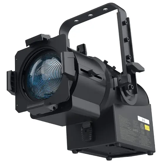
VARI-LITE VL600 Full Color LED Ellipsoidal Profile
Product Specifications
- Product Name: VL600 ACCLAIM PLE WW
- Manufacturer: Vari-Lite
- Model: VL600
- Color: Warm White (WW)
Product Usage Instructions
Introduction and Customer Support:
Welcome to the VL600 ACCLAIM PLE WW User Manual. Our goal is to provide you with exceptional customer service to ensure your business succeeds. Technical support is available for online assistance, repairs, maintenance contracts, and more. For customer service inquiries, visit our website or refer to the contacts in the back cover of this manual.
Additional Documentation and Resources:
- Additional product documentation, such as DMX maps and software downloads, can be accessed on our website.
- For detailed information on DMX512 control systems, consider purchasing the Recommended Practice for DMX512 guide from USITT.
Safety Warnings and Notices:
- Before installing or operating the VL600 fixture, read the user manual thoroughly to understand safety precautions.
- Only qualified personnel should handle installation and operation. Basic safety measures must be followed at all times to prevent injuries.
FAQ
- Q: Where can I find spare parts quotations and order spare parts?
- A: Customer Service manages spare parts quotations, order entry, and fulfillment. You can contact a customer service agent in your region through our website.
- Q: How can I access additional product documentation?
- A: Additional product documentation, including DMX maps and software downloads, can be found on our website for easy access.
- Q: What safety precautions should I follow when using the VL600 fixture?
- A: Always read and follow all safety instructions provided in the user manual. Avoid staring into the beam as the fixture is categorized as Risk Group 2 (RG2).
INTRODUCTION
OUR GOAL
We are committed to providing you the highest quality in customer service. Our comprehensive resources are available to help your business succeed and ensure you get the full benefit of being a Vari-Lite customer.
TECHNICAL SUPPORT
Our Service and Support team is tasked with online and field support, repair, demo, commissioning, mainte-nance contracts, and technical training for fixtures and systems. In addition, this team plays a large role in a Systems sales, responsible for administering final commissioning, record-keeping, and organizing services. Refer to the back cover of this User Manual for contacts in your region or visit www.vari-lite.com/support
CUSTOMER SERVICE
Customer Service is responsible for boxed goods and spare parts quotations, order entry and fulfilment, project delivery, lead times, and general account management. They also manage all after sales warranty fulfillment, RGA, and repairs invoicing in tandem with our After Sales Service & Support team. Visit our website to find a customer service agent in your region.
ADDITIONAL DOCUMENTATION
Additional product documentation, including DMX maps, software, and photometric reports, are available for download on our website.
For more information on installing DMX512 control systems, the following publication is available for purchase from the United States Institute for Theatre Technology (USITT), “Recommended Practice for DMX512: A Guide for Users and Installers, 2nd edition” (ISBN: 9780955703522).
USITT Contact Information:
- USITT
- 315 South Crouse Avenue, Suite 200 Syracuse, New York 13210-1844 USA
- Phone: 800-938-7488 or +1-315-463-6463
- Fax: 866-398-7488 or +1-315-463-6525
- Website: www.usitt.org
ABOUT THIS DOCUMENT
Read all instructions before installing or using this product. Retain this User Manual for future reference.
Additional product information and descriptions may be found on the product data sheet(s) which can be downloaded from the website at www.vari-lite.com.
This User Manual provides necessary information regarding safety, installation, operation and routine maintenance for VL600 Acclaim PLE WW. Familiarizing yourself with this information will help you to get the most out of your product.
WARNING: It is important to read ALL accompanying safety and installation instructions to avoid damage to the product and potential injury to yourself or others.
SAFETY INFORMATION
SAFETY WARNINGS AND NOTICES
Read this user manual in full before attempting to install, operate or maintain the fixture to which it relates. This user manual is intended to provide general guidance to such suitably qualified personnel. Installation and operation of the fixture are to be performed by qualified personnel only.
When using electrical equipment, basic safety precautions should always be followed including the following:
READ AND FOLLOW ALL SAFETY INSTRUCTIONS
- For indoor, dry location use only. Do not use outdoors unless fixture is suitably IP-rated.
- Use safety tether when mounting.
- Equipment should be mounted in locations and at heights where it will not be readily subjected to tampering by unauthorized personnel.
- Not for residential use. Do not use this equipment for other than intended use.
- Note distance requirement(s) from combustible materials or illuminated objects. Do not mount near gas or electric heaters.
- Install only in locations with adequate ventilation. Ensure sure that ventilation slots are not blocked.
- Ensure that the voltage and frequency of the power supply match the power requirements of the fixture.
- The fixture must be earthed/grounded to the appropriate conductor.
- Do not operate fixture outside the specified ambient temperature range.
- Do not connect the fixture to any dimmer pack.
- The use of accessory equipment not recommended by the manufacturer may cause an unsafe condition and void warranty.
- Refer service to qualifi ed personnel. This fixture contains no user serviceable parts.
- Prior to first use, carefully inspect fixture to ensure no damage has occurred during shipping.
- Materials used in the manufacturing process can cause strong odors when the product is new. These odors dissipate over time.
- Prior to each use, carefully inspect power cables and replace any damaged cables.
- Exterior surfaces of the luminaire will be hot during operation. Take appropriate precautions.
- Continuous use of the fixture may shorten the lifespan. Power down the fixture when not in use.
- Do not cycle power on and off repeatedly. Disconnect mains power if the fixture is not used for an extended period.
- Clean fixtures regularly, particularly when working in a dusty environment.
- Never touch power cables or wires while the fixture is powered on.
- Avoid entangling power wires with other cables.
- In the event of a serious operating problem, immediately discontinue using the fixture.
- It is hazardous to operate luminaires without lens or shield. Shields, lenses, or ultraviolet screens shall be changed if they have become visibly damaged to such an extent that their effectiveness is impaired, for example, by cracks or deep scratches.
- Original packing materials can be reused for transporting the fixture.
- Do not look directly at the LED light beam while the fixture is on.
- This is a Class A product. In a domestic environment this product may cause radio interference, in which case, the user may be required to take adequate measures.
- The light source contained in this luminaire shall only be replaced by the manufacturer or service agent or similarly qualified person.
SAVE THESE INSTRUCTIONS
WARNING: Refer to National Electrical Code® and local codes for cable specifications. Failure to use proper cable can result in damage to equipment or danger to personnel. Caution Against Direct Sunlight Through Front Lens Assembly
CAUTION! Do not stare into the beam. This fixture is categorized as Risk Group 2 (RG2).

FCC STATEMENT
FCC DECLARATION OF CONFORMITY
This equipment has been tested and found to comply with the limits for a Class A digital device pursuant to Part 15 of FCC Rules. These limits are designed to provide reasonable protection against harmful interference when this equipment is operated in a commercial environment. This equipment generates, uses, and can radiate radio frequency energy and, if not installed and used in accordance with the Vari-Lite system, service, and safety guidelines, may cause harmful interference to radio communications.
As tested under this standard:
FCC 47CFR 15B clA*CEI
Issued:2009/10/01 Title 47 CFR Part 15 Subpart B Unintentional Radiators Class A
Operation of this equipment in a residential area is likely to cause harmful interference, in which case the user will be required to correct the interference at his/her own expense.
EU DECLARATION OF CONFORMITY
We, Vari-Lite LLC., 10911 Petal Street, Dallas, Texas 75238, declare under our responsibility for the products contained herein are in conformity with the essential requirements of the following European Directives and harmonized standards:
Low Voltage Director (LVD), 2006/95/EC
- EN 60589-2-17:1984+A1:1987+A2:1990 used in conjunction with 60598-1:2008/A11:2009
Electromagnetic Compatibility Directive (EMC), 2004//108/EC
- EN 55022:2010, EN55024:2010
WARRANTY SERVICE
HOW TO OBTAIN WARRANTY SERVICE
A copy of the Limited Warranty card was included in the shipping package for this product.
To obtain warranty service, please contact customer service at 1-214-647-7880, or entertainment.service@signify.com and request a Return Material Authorization (RMA) for warranty service. You will need to provide the model and serial number of the item being returned, a description of the problem or failure and the name of the registered user or organization. If available, you should have your sales invoice to establish the date of sale as the beginning of the warranty period. Once you obtain the RMA, pack the unit in a secure shipping container or in its original packing box. Be sure to clearly indicate the RMA number on all packing lists, correspondence, and ship-ping labels. If available, please include a copy of your invoice (as proof of purchase) in the shipping container.
With the RMA number written legibly on or near the shipping address label, return the unit, freight prepaid, to:
- Vari-Lite LLC
- Attention: Warranty Service (RMA# ________) 10911 Petal Street
- Dallas, Texas 75238 USA
As stated in the warranty, it is required that the shipment be insured and FOB our service center.
IMPORTANT! When returning products to Vari-Lite for repairs (warranty or out-of-warranty) from a country other than the USA, “Vari-Lite LLC”, must appear in the address block as the Importer of Record (IOR) on all ship-ping documentation, Commercial Invoices, etc. This must be done in order to clear customs in a timely manner and prevent returns.
DESCRIPTION
FEATURES
- 500 W/650 W-equivalent LED profile engine – cost effective profile from the original name in theatrical lighting.
- Supports SPX lens system – works perfectly with industry standard lens system with a wide range of available beam angles.
- Four-blade manual shutter system –superior control to position light exactly where you need it.
- Optional angle-adjusting size B metal gobo holder – add depth and texture using industry-standard gobos. Easily adjust gobo angle within holder to get the perfect look.
- Adjustable yoke – mount fixture where you want it even when headroom is limited.
- Available in black or white – the perfect body color for your application.
COMPONENTS
The document provides installation and operation instructions for the following products:
- VL600 Acclaim PLE WW
Read all instructions before installing or using this product. Retain this manual for future reference. Additional product information and descriptions may be found on the product specification sheet.
INCLUDED ITEMS
Each VL600 Acclaim PLE WW luminaire includes the following items:
- VL600 Acclaim PLE WW
- Quick Start Guide
INSTALLATION
MOUNTING
The unit should be mounted via its screw holes on the bracket. Always ensure that the unit is firmly fixed to avoid vibration and slipping while operating. Always ensure that the structure to which you are attaching the unit is secure and is able to support 10 times the unit’s weight. Always use a safety cable that can hold up to 12 times the weight of the unit when installing the fixture. The luminaire must be mounted by professionals.

NOTE: Lens tube sold separately.
LENS INSTALLATION
To install lens:
- Step 1. Pull the locking lever on the lens tube toward the front of the lens.

- Step 2. Slide the lens tube down into the body until the locking lever can latch. Loosen focus lock knob and adjust focus as desired. Tighten to lock. Reverse process to remove.
- Visit www.vari-lite.com for a complete list of compatible lens tubes.

- Visit www.vari-lite.com for a complete list of compatible lens tubes.
NOTE
- Lens tube may need to be moved foward (away from the body) to install or remove. Loosen focus lock knob to adjust.
GOBO HOLDER INSTALLATION
| VL600 acclaim gobo holder (B-size) | 912400576897 | 64511-012 |
To install the gobo holder:
- Step 1. Loosen the two screws at A and move the shading plate backward Tighten the two screws to fix it.

- Step 2. Snap the gobo holder into the luminaire.

IRIS INSTALLATION
| VL600 acclaim 16-leaf iris | 912400576949 | 64511-013 |
Install the iris:
- Step 1. Loosen the two screws at A and move the shading plate backward. Tighten the two screws.

- Step 2. Snap the iris into the luminaire as shown.

CONNECTING DATA AND POWER
- A maximum of 32 luminaires may be connected in any one DMX data link.
- A maximum of 9 luminaires may be connected in 120V, 60Hz.
- A maximum of 16 luminaires may be connected in 230V, 50Hz.
NOTE
- This maximum limit applies to the luminaire “daisy chain” only.
- Your system or console may require fewer luminaires on a single data link path. Consult your console documentation for more information.
To connect power and data:
- Step 1. Connect data cable from console to first luminaire in chain at DATA IN connector.
- Step 2. If required, connect additional data cables from DATA THRU connectors to DATA IN connectors of remaining luminaires in link.
- Step 3. At last luminaire in link, install male termination connector at DATA THRU connector. (Luminaires and other devices on the same DMX chain may not function properly without termination.)

- Step 4. Connect AC Input Cable connector to power input source.
- Step 5. Dress AC input and data cables and secure them so that they will not interfere with luminaire head and yoke movement.
CONTROL PANEL

- LCD display – shows menu and selected function
- Buttons:
- MENU – to select programming functions
- DOWN – to go forward in selected functions
- UP – to go backward in selected functions
- ENTER – to confirm the selected function
- FUSE (T 3.15A) – protects the unit from overcurrent damage
- POWER IN – connects to power supply
- POWER OUT – connects to next fixture
- DMX IN – 5-pin XLR cable to link the DMX console
- DMX OUT – 5-pin XLR cable to link next fixture
Press the MENU button to select any functions, until the required function is shown in the display. Select the desired function by pressing ENTER, which will cause the display to blink. Use the UP and DOWN button to change the mode. Once the required mode has been selected, press the ENTER button to accept the selection, otherwise after a period of one minute wait, the menu will return automatically to the main functions, without any changes having been made. Return to the main functions without making any changes by pressing the MENU button.
| BUTTON
COMBINATION |
FUNCTION |
| Menu + Enter | Factory defaults |
| Enter + UP | Turns the fixture on at full output |
| Enter + Down | Toggles through standard, studio, and Whisper modes |
| UP + Down | Inverts display |
MENU UI STRUCTURE
| MENU UI STRUCTURE | |||||||||
| LEVEL 1 | LEVEL 2 | LEVEL 3 | LEVEL 4 | LEVEL 5 | LEVEL 6 | DEFAULT | RDM ACTIVATION | DESCRIPTION | RESET TO DEFAULT UI |
|
DMX |
address | 001~512 | Get status & Change – lTP | set DMX address | set address to 001 | ||||
|
DMX Mode |
8 – Bit | (Default) | Get status & Change – lTP |
set Dmx Mode |
reset to Default |
||||
| 16 – Bit | |||||||||
|
Data |
Ch 1 – Intensity XXX (Value) |
Get status |
Check incoming DMX data value |
reset to Default |
|||||
| Ch 2 – Intensity Fine XXX (Value) | |||||||||
| ……all functions | |||||||||
|
Dmx Fail |
DMX Hold | (Default | Get status & Change – lTP | set choice on DMX fail |
reset to Default |
||||
| Blackout | |||||||||
|
Manual |
Dimmer |
0-255 |
(Default – 0) |
n/a |
Manual control of leD (will hold if active on power cycle)
exiting manual mode drops control |
reset to Default |
|||
|
settings |
leD |
Dimming Curve |
square law | (Default) |
Get status & Change – lTP |
Dimmer curve selection – Dimming smoothness remain active at all times there is no Dim snap off fucntion, with the exception of using the strobe channel when strobing the fixture shall always snap on/off with no smoothing |
reset to Default |
||
| s Curve | |||||||||
|
linear |
|||||||||
|
Output Mode |
standard | (Default) |
Get status & Change – lTP |
Output mode – standard Max output highest fan speed |
reset to Default |
||||
| studio | |||||||||
| Whisper | |||||||||
|
Fan Mode |
On |
Get status & Change – lTP |
On – Fan runs continuously auto – Fan ramps up and down as required by leD output |
reset to Default |
|||||
|
auto |
(Default) |
||||||||
|
refresh rate |
500Hz |
Get status & Change – lTP |
leD Frequency adjustment * reduce the number to smaller feasible list |
reset to Default |
|||||
| 1000Hz | |||||||||
| 1500Hz | (Default) | ||||||||
| 2000Hz | |||||||||
| 2500Hz | |||||||||
| 3000Hz | |||||||||
| 3500Hz | |||||||||
| 4000Hz | |||||||||
| Display On Time | auto (30 seconds since last press) | (Default ) | Get status & Change – lTP | UI screen time / no Orientation required at this level |
reset to Default |
||||
| On | |||||||||
| reset Defaults |
Are you sure? |
Get status & Change – lTP | Menu/excape = no enter = Yes Factory reset | ||||||
|
service |
status |
(no errors… or displays a list of errors) | Give list of fixture errors | Get status |
Fixture service area |
excluded |
|
Diagnostics |
Fan Check | Give fans speeds | Get status | excluded | ||
| Temp | Give leD / Fixture temperatures | Get status | excluded | |||
| Version | VXXX (MM/DD/YY | Get status | excluded | |||
| Fixture Hours | Gives Fixture run time hours / leD hours | Get status | excluded | |||
| Cross load (software) | Are you sure? send | n/a | excluded | |||
NOTE
- Not all menu options are available for every fixture.
DMX MENU
- Choose DMX, press the ENTER button to confirm, use the UP/DOWN button to choose from options listed.
ADDRESS
- Choose Address, press the ENTER button to confirm. Use the UP/DOWN button to select range of values.
- Press the ENTER button to store. Press the MENU button to return to previous menu or let the unit idle one minute to exit.
DMX MODE
- Choose DMX Mode, press the ENTER button to confirm. Use the UP/DOWN button to select mode.
- Press the ENTER button to store. Press the MENU button to return to previous menu or let the unit idle one minute to exit.
DATA
- Choose Data, press the ENTER button to confirm. Use the UP/DOWN button to select option.
- Choose Ch1 – Intensity xxx(value), Ch2 – Intensity Fine xxx(Value), …. All functions, press the ENTER button to store. Press the MENU button to return to previous menu or let the unit idle one minute to exit menu mode.
DMX FAIL
- To select DMX Fail, press the ENTER button to confirm. Use the UP/DOWN button to select DMX Hold or Blackout, press the ENTER button to store. Press the MENU button back to the last menu or let the unit idle one minute to exit menu mode.
MANUAL MENU
To select Manual, press the ENTER button to confirm, use the UP/DOWN button to select Red, Green, Blue and Lime. Use the UP/DOWN button to adjust the value from 0 to 255, press the ENTER button to store. Press the MENU button back to the last menu or let the unit idle one minute to exit menu mode.
SETTINGS MENU
- Choose Settings, press the ENTER button to confirm, use the UP/DOWN button to choose from options shown on screen.
LED
- Choose LED, press the ENTER button to confirm. Use the UP/DOWN button to select an option. Press the ENTER button to store. Press the MENU button to return to previous menu or let the unit idle one minute to exit menu mode.
DIMMING CURVE
- To Choose Dimming Curve, press the ENTER button to confirm. Use the UP/DOWN button to Choose Square Law Curve, S Law Curve or Linear Law Curve, press the ENTER button to store.
- Press the MENU button to return to previous menu or let the unit idle one minute to exit menu mode.

OUTPUT MODE
- Choose Output Mode, press the ENTER button to confirm. Use the UP/DOWN button to select Standard, Studio, or Whisper. Press the MENU button to return to previous menu.
COlOR CALIBRATION
- Choose Color Cal, press the ENTER button to confirm. Use the UP/DOWN button to Choose ON or OFF. Press the MENU button to return to previous menu.
Fan MODE
- Select Fan Mode, press the ENTER button to confirm. Use the UP/DOWN button to select On or Auto, press the ENTER button to store.
- Press the MENU button back to the last menu or let the unit idle one minute to exit menu mode.
REFRESH RATE
- Select Refresh Rate, press the ENTER button to confirm. Use the UP/DOWN button to select 500Hz, 1000Hz, 1500Hz, 2000Hz, 2500Hz, 3000Hz, 3500Hz, 4000Hz, press the ENTER button to store.
- Press the MENU button back to the last menu or let the unit idle one minute to exit menu mode.
DISPLAY ON TIME
- To select Display On Time, press the ENTER button to confirm. Use the UP/DOWN button to select Auto(30 seconds since last press) or On, press the ENTER button to store.
- Press the MENU button back to the last menu or let the unit idle one minute to exit menu mode.
RESET DEFAULTS
- To select Reset Defaults, press the ENTER button to confirm, Are You Sure? will show on the display, press the ENTER button to store.
- Press the MENU button back to the last menu or let the unit idle one minute to exit menu mode.
SERVICE
SERVICE MENU
- To select Service, press the ENTER button to confirm, use the UP/DOWN button to select Status, Diagnostics, Version, Fixture Hours, Crossload(Software) and Password(2606).
STATUS
- To select Status, press the ENTER button to confirm, No Errors or a list of errors will show on the display, press the MENU button back to exit.
DIAGNOSTICS
- To select Diagnostics, press the ENTER button to confirm. Use the UP/DOWN button to select Fan Check or Temp, press the ENTER button to store. Press the MENU button back to the last menu or let the unit idle one minute to exit menu mode.
VERSION
- To select Version, press the ENTER button to confirm, Version will show on the display, press the MENU button back to exit.
FIXTURE HOURS
- To select Fixture Hours, press the ENTER button to confirm, Fixture Hours will show on the display, press the MENU button back to exit.
CROSSLOAD(SOFTWARE)
- Select Crossload(Software), press the ENTER button to confirm, Are You Sure? will show on the display, press the
- ENTER button to store. Press the MENU button back to the last menu or let the unit idle one minute to exit menu mode.
NOTE
- Incoming DMX must be removed from the fixture or software crossload will not be activated.
PASSWORD
- Select Password(2606), press the ENTER button to confirm. Use the UP/DOWN button to select White Balance or Change Mode, press the ENTER button to store.
- Press the MENU button back to the last menu or let the unit idle one minute to exit menu mode.
WHITE BALANCE
- To select White Balance, press the ENTER button to confirm. Use the UP/DOWN button to select Red, Green, Blue, Lime or Reset to Defaults (Reset to White Balance), press the ENTER button to store.
- Press the MENU button back to the last menu or let the unit idle one minute to exit menu mode.
CHANGE MODE
- To select Change Mode, press the ENTER button to confirm. Use the UP/DOWN button to select Zoomspot, PLE, Fresnel or Cyc, press the ENTER button to store. Press the MENU button back to the last menu or let the unit idle one minute to exit menu mode.
DMX MAPPING
The fixture can be operated by DMX controller. The following tables assumes a DMX start address of 1.
When a different starting address is used, this address becomes channel 1 function and other functions follow in sequence.
| DMX CHANNEL 8-BIT (DEFAULT) | DMX CHANNEL 16-BIT | PARAMETER | DEFAULT | RANGE | DESCRIPTION |
| 1 | 1 | Intensity (16-Bit High) | 0 | 0 – 255 |
intensity (Dimmer) control channel |
| 2 | Intensity (16-Bit Low) | 0 – 65535 (16Bit) | |||
|
2 |
3 |
Strobe |
0 |
0 | Open |
| 1 -255 | Strobe speed Slow>>>>>>>>>>>>>>>>>>>Fast |
RDM PARAMETER IDs
Remote Device Management (RDM) is a protocol enhancement to USITT DMX512 that allows bi-directional communication between a lighting or system controller and attached RDM compliant devices over a standard DMX line. This protocol will allow configuration, status monitoring, and management of these devices in such a way that does not disturb the normal operation of standard DMX512 devices that do not recognize the RDM protocol.
| ACCLAIM LED PLE WW RDM PRODUCT PARAMETER IDS | ||||
| Model ID | Manufacturer | Vendor ID | Model Description | Product Category |
| 0x0113 | Vari-lite | 0x564C | Vl600 aCClaIM Ple WW | 0x0101 |
The table on the following pages outlines and describes all the RDM parameters IDs associated with the VL600 ACCLAIM PLE WW.
| GET ALLOWED | SET ALLOWED | RDM PARAMETER IDS | VALUE | COMMENT | ESTA STANDARD | REQUIRED / | DMX / UI DESCRIPTION |
| Category – network Management | |||||||
| DIsC_UnIQUe_BranCH | 0x0001 | X | X | ||||
| DIsC_MUTe | 0x0002 | X | X | ||||
| DIsC_Un_MUTe | 0x0003 | X | X | ||||
| X | PrOXIeD_DeVICes | 0x0010 | |||||
| X | PrOXIeD_DeVICes_COUnT | 0x0011 | |||||
| X | X | COMMs_sTaTUs | 0x0015 | ||||
| Category – status Collection | |||||||
| X | QUeUeD_MessaGe | 0x0020 | |||||
| X | sTaTUs_MessaGes | 0x0030 | X | status | |||
| X | sTaTUs_ID_DesCrIPTIOn | 0x0031 | X | ||||
| X | Clear_sTaTUs_ID | 0x0032 | |||||
| X | X | sUB_DeVICe_sTaTUs_ rePOrT_THresHOlD | 0x0033 | ||||
| Category – rDM Information | |||||||
| X | sUPPOrTeD_ParaMeTers | 0x0050 | X | X | |||
| X | ParaMeTer_DesCrIPTIOn | 0x0051 | X | X | |||
| Category – Product Information | |||||||
| X | DeVICe_InFO | 0x0060 | X | X | |||
| X | PrODUCT_DeTaIl_ID_lIsT | 0x0070 | |||||
| X | DeVICe_MODel_ DesCrIPTIOn | 0x0080 | X | ||||
| X | ManUFaCTUrer_laBel | 0x0081 | X | ||||
| X | X | DeVICe_laBel | 0x0082 | X | |||
| X | X | FaCTOrY_DeFaUlTs | 0x0090 | X | reset Defaults | ||
| X | lanGUaGe_CaPaBIlITIes | 0x00a0 | |||||
| X | X | lanGUaGe | 0x00B0 | ||||
| X | sOFTWare_VersIOn_ laBel | 0x00C0 | X | X | Version | ||
| X | BOOT_sOFTWare_ VersIOn_ID | 0x00C1 | |||||
| X | BOOT_sOFTWare_ VersIOn_laBel | 0x00C2 | |||||
| Category – DMX512 setup | |||||||
| X | X | DMX_PersOnalITY | 0x00e0 | X | DMX Mode | ||
| X | DMX_PersOnalITY_ DesCrIPTIOn | 0x00e1 | X | ||||
| X | X | DMX_sTarT_aDDress | 0x00F0 | X | X | address | |
| X | slOT_InFO | 0x0120 | X | ||||
| X | slOT_DesCrIPTIOn | 0x0121 | X | ||||
| X | DeFaUlT_slOT_ValUe | 0x0122 | X | ||||
| Category – sensors 0x02xx Use | |||||||
| X | sensOr_DeFInITIOn | 0x0200 | X | ||||
| X | X | sensOr_ValUe | 0x0201 | Fan speed and | X | Diagnostics | |
| X | reCOrD_sensOrs | 0x0202 | |||||
| Category – Dimmer settings 0x03xx – FUTUre Use | |||||||
| X | X | Dimmer Curve | 0x0343 | X | |||
| X | Dimmer Curve Description | 0x0344 | X | ||||
| X | X | Modulation Frequency | 0x0347 | X | |||
| X | Modulation Frequency Description | 0x0348 | X | ||||
| Category – Power / lamp settings 0x04xx | |||||||
| X | X | DeVICe_HOUrs | 0x0400 | X | Fixture Hours | ||
| X | X | laMP_HOUrs | 0x0401 | ||||
| X | X | laMP_sTrIKes | 0x0402 | ||||
| X | X | laMP_sTaTe | 0x0403 | ||||
| X | X | laMP_On_MODe | 0x0404 | ||||
| X | X | DeVICe_POWer_CYCles | 0x0405 | ||||
| Category – Display settings 0x05xx | |||||||
| X | X | DIsPlaY_InVerT | 0x0500 | ||||
| X | X | DIsPlaY_leVel | 0x0501 | ||||
| Category – Configuration 0x06xx | |||||||
| X | X | Pan_InVerT | 0x0600 | ||||
| X | X | TIlT_InVerT | 0x0601 | ||||
| X | X | Pan_TIlT_sWaP | 0x0602 | ||||
| X | X | real_TIMe_ClOCK | 0x0603 | ||||
| Category – Control 0x10xx | |||||||
| X | X | IDenTIFY_DeVICe | 0x1000 | X | X | ||
| X | reseT_DeVICe | 0x1001 | X | ||||
| X | X | POWer_sTaTe | 0x1010 | ||||
|
X |
X |
PerFOrM_selFTesT |
0x1020 |
all Test, Pan/Tilt, encoder | |||
| X | selF_TesT_DesCrIPTIOn | 0x1021 | |||||
| X | CaPTUre PreseT | 0x1030 | see e1- 20_2010a | ||||
| X | X | PreseT PlaYBaCK | 0x1031 | Table a-7 defines | |||
| esTa reserved Future rDM | 0x7Fe0-
0x7FFF |
||||||
| Manufacturer-specific PIDs | 0x8000-
0xFFDF |
||||||
|
X |
X |
Output Power Mode |
0x8a97 |
Value range depends on options (standard, studio, etc) |
X |
led Output Mode | |
| X | X | Pan/Tilt Feedback (On/Off) | 0x8aD3 | ||||
|
X |
X |
Display On Time |
0x8aa0 |
Value range depends on options |
X |
Display On Time | |
|
X |
X |
Led Dimmer Curve |
0x8aa1 |
Value range depends on options | Led Dimming Curve | ||
| X | X | Pan Tilt Movement (On/Off) | 0x8aa2 | ||||
| X | X | Head Motor Movement (On/ Off) | 0x8aa3 | ||||
|
X |
X |
auto shutdown Mode |
0x8aa4 |
Value range depends on options | |||
| X | X | leD Hours | 0x8aa5 | ||||
| X | X | Dim snap (On/Off) | 0x8aa6 | ||||
| X | X | Color snap (On/Off) | 0x8aa7 | ||||
| X | X | auto Fan Mode (On/Off) | 0x8aa8 | Led Fan Mode | |||
|
X |
X |
Gamma shift |
0x8aa9 |
Value range depends on options | |||
| X | X | Tungsten Dimming (On/ Off) | 0x8aaa | ||||
| X | X | CTB Correction (On/Off) | 0x8aaB | ||||
|
X |
X |
led refresh rate |
0x8aaC |
Value range depends on options | led refresh rate | ||
| X | X | side Hang (On/Off) | 0x8aaD | ||||
| X | X | Focus Track (On/Off) | 0x8aae | ||||
| X | Control signel select DMX only/artneT (On/Off) | 0x8aaF | |||||
|
X |
Recalibrate fixture (level) |
0x8aB0 |
different levels (all, position, color, etc) | ||||
| X | X | DMX Fail (Hold, Blackout, GOTO Preset) | 0x8aB1 | DMX Fail | |||
| X | X | artnet Universe | 0x8aB2 | ||||
| X | X | artnet net | 0x8aB3 | ||||
| X | X | artnet sub-net | 0x8aB4 | ||||
| X | X | artnet ethernet IP | 0x8aB5 | ||||
| X | X | artnet ethernet sub-net Mask | 0x8aB6 | ||||
| X | X | Manual PreseT Playback Power Up Preset | 0x8aB7 | ||||
| X | X | Manual PreseT Playback Preset Intensity | 0x8aB8 | ||||
| X | X | Manual PreseT Playback Priority | 0x8aB9 | ||||
| X | X | Manual PreseT Playback Power Up? | 0x8aBa | ||||
|
X |
X |
Led Color Calibration (On/ Off) |
0x8aBB |
X |
Led Color Calibration |
Appendix A
CARE AND MAINTENANCE
TROUBLeSHOOTinG
The following are a few common problems that may occur during operation.
- Luminaire does not work; light and fan do not turn on.
- Check power connection and main fuse.
- Measure the mains voltage on the main connector.
- Not responding to DMX controller.
- If DMX LED is not illuminated, verify that the DMX cables are properly connected.
- If the DMX LED is illuminated and there is no response, verify DMX address settings and the DMX polarity.
- If you experience intermittent DMX signal problems, check the pins on the connectors or on the PCB.
- Test with a different DMX controller.
- Check if the DMX cables run near or alongside high voltage cables that may cause interference to the DMX interface circuit.
CLEANING
Cleaning the inside of the luminaire must be carried out periodically in order to optimize the light output. Cleaning frequency depends on the environment in which the fixture operates. Damp, smoky or particularly dusty surroundings can cause greater accumulation of dirt on the fixture’s optics.
- Clean with a soft cloth using glass cleaning fluid.
- Dry parts carefully.
- Clean the external optics at least every 30 days.
Appendix B
FAN SPEED AND CONTROL
FAN SPEED AND CONTROL
All Vari-lite luminaires will be governed by the same Fan speed v Noise levels v Maximum power output rules as details below. These noises related to these levels will confirm to Noise Criteria levels details of which are contained within the document.
There are 3 control parameters can be selected separately or in conjunction when permitted to manage Fan speed v Noise levels v Maximum power output.

NOTE: Not all features have all modes or functions refer to DMX map and User interface menu tree to see if you product has one of more of these functions. tem 1 – Fan ‘v’ Output Preset Modes
- These modes are selectable at either/or the fixture DMX control channel or via the fixture user interface screen. The section of the modes works in conjunction with Items 3 and will also active or deactivate the Item 2.
- Boost mode – LED output boosted to >120% of standard output fan speeds increased manage heat level of LED (may be limited to only run for XXhrs). Fixture will not exceed NC45 – NC55 sound levels in this mode
- Standard mode – Full LED Output + Fan Spin at top speed (loudest setting). The fixture will not exceed NC40 sound levels in this mode
- Studio Mode – Fan speed reduced to the appropriate amount to reduce dB levels >10% of full speed + LED @ max output approximately 80% of Standard output at appropriate level to ensure LED work at optimum temperature and output efficiency (fan speed remains at a constant speed and do not ramp up or down) NC35
- Whisper mode – Fan speed reduced to appropriate amount to reduce dB levels to >30% of the full speed + LED Max output approximately 60% of Standard output at an appropriate level to ensure LED work at optimum temperature and output efficiency (Fan speed remains at a constant speed and do not ramp up or down) NC25
- Silent Mode – ideally Fans do not spin + output is capped at an appropriate level to ensure LED work at optimum temperature and output efficiency (Fan should never switch on in this mode or change speed if they on) NC15 target level.
| Mode | Led OUTPUT | Fan Speed | Noise Criterion | Equivalent Sound Level dBA (@3M) |
| Boost Mode | >100% | Boosted fan speed constant | NC45 | 50 |
| Standard Mode | Full 100% | Full 100% constant | NC40 | 45 |
| Studio Mode | 80% | Appropriate speed to reduce dB levels >10% of full speed | NC35 | 40 |
| Whisper Mode | 60% | Appropriate speed to reduce dB levels >30% of full speed | NC25 | 35 |
| Silent Mode | TBC | Fan off | NC15 | 25 |
| Noise Criterion | OCTAVE BAND CENTER FREQUENCY (H7) | |||||||
| 63 | 125 | 250 | 500 | 1000 | 2000 | 4000 | 8000 | |
| SOUND PRESSURE LEVELS (DB) | ||||||||
| NC-15 | 47 | 36 | 29 | 22 | 17 | 14 | 12 | 11 |
| NC-20 | 51 | 40 | 33 | 26 | 22 | 19 | 17 | 16 |
| NC-25 | 54 | 44 | 37 | 31 | 27 | 24 | 22 | 21 |
| NC-30 | 57 | 48 | 41 | 35 | 31 | 29 | 28 | 27 |
| NC-35 | 60 | 52 | 45 | 40 | 36 | 34 | 33 | 32 |
| NC-40 | 64 | 56 | 50 | 45 | 41 | 39 | 38 | 37 |
| NC-45 | 67 | 60 | 54 | 49 | 46 | 44 | 43 | 42 |
| NC-50 | 71 | 64 | 58 | 54 | 51 | 49 | 48 | 47 |
| NC-55 | 74 | 67 | 62 | 58 | 56 | 54 | 53 | 52 |
| NC-60 | 77 | 71 | 67 | 63 | 61 | 59 | 58 | 57 |
| NC-65 | 80 | 75 | 71 | 68 | 66 | 64 | 63 | 62 |
| NC-70 | 83 | 79 | 75 | 72 | 71 | 70 | 69 | 68 |
TECHNICAL SUPPORT
GLOBAL 24HR TECHNICAL SUPPORT:
- Call: +1 214 647 7880
- entertainment.service@signify.com
NORTH AMERICA SUPPORT:
EUROPEAN CUSTOMER SERVICE CENTER:
- Call: +31 (0) 543 542 531
- entertainment.europe@signify.com
©2024 Signify Holding. All rights reserved.
All trademarks are owned by Signify Holding or their respective owners. The information provided herein is subject to change, without notice. Signify does not give any representation or warranty as to the accuracy or completeness of the information included herein and shall not be liable for any action in reliance thereon. The information presented in this document is not intended as any commercial offer and does not form part of any quotation or contract, unless otherwise agreed by Signify. Data subject to change.
Documents / Resources
 |
VARI-LITE VL600 Full Color LED Ellipsoidal Profile [pdf] User Manual VL600 Full Color LED Ellipsoidal Profile, VL600, Full Color LED Ellipsoidal Profile, LED Ellipsoidal Profile, Ellipsoidal Profile |