![]()
 CH341A پروگرامر صارف کا دستی (رنگین لائٹ ورژن)
CH341A Programmer Instructions
(Color Light Version v1.5, v1.6, v1.7 Universal)
2023/8/18 Contents Table of Contents
CH341A پروگرامر کا تعارف
Our compact ch341a programmer is only 22mm*50mm in length and width, easy to carry around, with integrated level shifter circuitry, supporting 1.8v minimum. Based on the compact and convenient design considerations, so through the toggle switch K1 to change the voltage, can support 5v, 3.3v, 2.5v, 1.8v, also supports ttl output (minimum support 1.8v standard) It can be described as compact and multi-functional, burn 8-pin chip and not fall down the serial port brush, while integrated infrared code module. spi interface output support for low-voltage، حاصل کرنے کے لیے K1 ٹوگل کے ذریعے بھی۔
سافٹ ویئر ڈاؤن لوڈ: http://198.11.174.230/ch341a-Software.zip
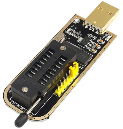
This is what our programmer looks like
Plug directly into the usb port and try to avoid grabbing space with other usb devices.
Meanwhile, in order to adapt to most of the 8-pin chips, we have also equipped with simple adapter boards for 25xx, 24xx, 93xx, 45xx and other packages, in order to fulfill the needs in one step. We will also design adapter boards for the packages you need later.
We have labeled the interface and voltagای بورڈ پر سوئچ کر رہا ہے، لہذا آپ کو مزید ہدایات نہ ملنے کے بارے میں فکر کرنے کی ضرورت نہیں ہے۔
Differences between v1.5, v1.6 and v1.7:
*Locking Block 25xx, 24xx No Resistor Pull-Up and Down
*v1.6 Locking Block 25xx Partial Resistor Pull-Up
*v1.7 Locking Block 25xx partial resistor pull-up, 24xx partial resistor pull-down
بیان:
The ch341a programmer hardware is designed and developed by us and is copyrighted.
The software is open source or shareware and the copyright (authorship) belongs to them, please respect the fruits of their labor and thank them for their dedication and contribution to the programmer industry.
پروگرامر کا ہارڈ ویئر حصہ
پروگرامر ڈیزائن نسبتاً چھوٹا ہے، استعمال کرنے کے لیے براہ راست USB پورٹ میں داخل کیا جا سکتا ہے، ہر انٹرفیس اور جمپر فنکشن میں آن بورڈ ہدایات ہوتی ہیں، زیادہ تر معاملات کو ہدایات کو دیکھے بغیر سمجھا جا سکتا ہے۔ پروگرامر نے لیول شفٹر سرکٹری کو مربوط کیا ہے اور کم از کم والیوم کو سپورٹ کرتا ہے۔tage of 1.8v. Based on the compact and convenient design considerations, so through the toggle switch KI to change the voltage, can support 5v, 3.3v, 2.5v, 1.8v, also supports ttl output (minimum 1.8v low level) Directly support most of the 1.8v 24, 25 chips without the need for level shifter boards, such as w25q64fw, w25q128fw and so on. 1. Chip placement method
Please refer to the diagram below for placement of the chips, noting the orientation of the chips
ہم 16 پن لاکنگ سیٹ استعمال کرتے ہیں، ہر 8 پن پر چپ جلانے کی ایک سیریز کرنے کے لیے، بورڈ نے لوگو کی سمت رکھی ہے۔ 45xx اور 93xx چپس ہولڈرز کا استعمال کرتی ہیں، لیکن آپ چپس کو براہ راست لاکنگ ہولڈرز میں نہیں ڈال سکتے، اس سے چپس جل جائیں گی، براہ کرم اس پر توجہ دیں، آپ اسے محسوس کرنے کے لیے صرف ہمارے فراہم کردہ خصوصی اڈاپٹر کا استعمال کر سکتے ہیں۔ براہ کرم نوٹ کریں کہ اڈاپٹر بورڈ پر چپ کو ہولڈر کے اس حصے میں ڈالنے کے لیے ہدایات موجود ہیں۔
2. آؤٹ پٹ جلدtagای ووٹ
آریھ میں K1 نشان زدہ اور پروگرامر کی پشت پر جمپر کی ہدایات دیکھیں۔ یہ ریڈ/رائٹ چپ اور سپی پن آؤٹ پٹ والیوم ہے۔tage، تمام K1 ٹوگل کے ذریعے مختلف والیوم حاصل کرنے کے لیےtages بیک ٹوگل سوئچ پوزیشن والیوم کے مطابقtagای شناخت
 The programmer K1 position is normally issued for 3.3v.
**Toggle switch K1 increases the voltage all the way from the latch to the usb port.
**Please adjust the voltage چپ کو جلانے سے پہلے ہائی والیوم کی وجہ سے چپ کو جلانے سے بچنے کے لیےtagای، پاور اپ ہونے کی حالت میں پروگرامر میں ٹوگل سوئچ K1 کو آپریٹ نہیں کیا جا سکتا، براہ کرم پروگرامر کو ڈائل اپ کرنے کے لیے ان پلگ کریں اور پھر پلگ ان کریں!
The toggle position is shown below:
a) 1.8v toggle switch position reference
b) 2.5v ٹوگل سوئچ پوزیشن کا حوالہ
c) 3.3v ٹوگل سوئچ پوزیشن کا حوالہ (پہلے سے طے شدہ)
 d) 5v ٹوگل سوئچ پوزیشن کا حوالہ

3. spi output (programmer mode)
Programmer J1 pin numbering, with corresponding description on the back
پروگرامر کی ڈیفالٹ ترتیب spi آؤٹ پٹ J1 کے 1-2 پن کو مختصر کرنا ہے۔ ذیل میں J1 آؤٹ پٹ پن فنکشنز کی فہرست ہے۔
| J1 | 112 | 3 | 4 | 5 | 6 | 7 | 8 | 9 | 10 | 11 | 12 |
| function ality | SPI/TTL | IR | 2 | TXD | سی ایل کے | 6 | موسی | ایم آئی ایس او | جی این ڈی | ووٹ | 5v |
Here we only use pin 6~ 11. Refer to entry 1 for the Vout voltage وضاحت.
Through the spi interface to read and write chips on the board, please note that the wiring should not be too long, there will be interference or speed drop or can not recognize the chip, the reference line length of 10cm or so, depending on the circumstances of the set.
4. TTL output
پروگرامر کے J1 پن نمبر کی پشت پر متعلقہ تفصیل کے ساتھ لیبل لگا ہوا ہے۔ ٹی ٹی ایل کی سطح مختلف والیوم کو محسوس کر سکتی ہے۔tagای موڈز، جن کا احساس Vout والیوم کو ترتیب دے کر کیا جاتا ہے۔tagJ2 کا ای۔ سابق کے لیےampلی، اگر آپ کو 5v لیول کی ضرورت ہے، تو صرف Vout کو 5v پر جائیں؛ 3.3v کی سطح کے لیے، Vout چھلانگ لگا کر 3.3v پر جاتا ہے۔ 1.8v کی سطح کے لیے، Vout چھلانگ لگا کر 1.8v تک پہنچ جاتا ہے۔ یہ فنکشن پروگرامر کا سیریل پورٹ فنکشن ہے، آؤٹ پٹ ٹی ٹی ایل لیول ہے، سی پی یو کے سیریل پورٹ کمیونیکیشن پر براہ راست ڈوک کیا جا سکتا ہے، مندرجہ ذیل چارٹ کا جمپر حوالہ
 J1 pins 1 and 2 are unplugged from the jumper The following is a description of the function of J1
| J1 | 1 | 2 | 3 | 4 | 5 |
| فعالیت | SPI/TTL | IR | آر ایکس ڈی | TXD | |
When flashing, you can directly connect J1’s 4,
5, 10 will work 5, TTL self test
To test if the TTL interface is working properly, short J1 pins 4 and 5 as shown below. Available general-purpose serial port software to test whether the serial port can send and receive data, we here to provide a simple test tool, test multiple rates at a time to finish
The software is in the root directory of the package, please run “USB-TTL Detection.exe” and set your serial port number.
ٹیسٹ شروع کرنے کے لیے اسٹارٹ پر کلک کریں۔ اگر آپ کو NG پیغام ملتا ہے، تو براہ کرم چیک کریں کہ آیا شارٹنگ کی پوزیشن درست ہے۔
6. Infrared code measurement
Using the ttl function of the programmer to realize infrared code measurement, together with the special code measurement software can realize the code measurement of remote control and other infrared devices.
ذیل میں J1 کی ایک فعال وضاحت ہے۔
| J1 | 1 | 2 | 3 | 4 | 5 |
| فعالیت | SPI/TTL | IR | آر ایکس ڈی | TXD | |
Here we need to short pin 3 and 4 of J1 to realize code measurement, and K1 should be switched to 3.3v or 5v at the same time. Run the “RC Analyzer Fix.exe” software in the package.  Select the serial port number of the 341 and open the serial port.
 پیمائش کوڈ ڈسپلے کو سمجھنے کے لیے اپنے ریموٹ کنٹرول کو دبائیں، اس کے ساتھ ڈی کوڈنگ پرامپٹ بھی۔ پروگرامر کو استعمال کرنے کے بعد ان پلگ کرنے سے پہلے سیریل پورٹ کو بند کرنے کے لیے ٹیپ کرنا یاد رکھیں۔
رنگین لائٹس کی تفصیل
Colorful light version has 3 main colors Power red, plug in the usb is always on
Read/Write 24 Chip, Green, Flashes When Reading/Writing
Read/write 25, 93, 45 chips, blue, flashing mixed colors when reading/writing is colored
TTL is also flashing when brushing or testing.
IR code measurement, the light will also flash, but not so obvious, code measurement jump connection after plugging in the usb light will be on!
سادہ اڈاپٹر بورڈز اور برن ان بلاکس استعمال کرتے ہیں۔
1. Universal adapter plate
Universal 8pin adapter board can be used for 24xx, 25xx, but the sop16 pads on the board can only be used for 25 chips, and there is also a chip clip interface, please correspond to the pin wiring, the pin number is the same as the chip pin number.  اگر آپ کو روٹری سی ایل کے پنوں کو سولڈر کرنے کی ضرورت ہے۔amp، براہ کرم پہلے پنوں کو سولڈر کریں، بصورت دیگر وہ دوسرے پنوں کے ذریعہ پن کیے جائیں گے، اور پھر پنوں کو ہولڈر پر سولڈر کریں۔
2. 93xx chip placement method diagram
The 93xx chips are read/written using Block 25, so you need to put the adapter board into that position. Please note that you cannot put the 93 chip directly into the locking seat, the pins do not correspond to each دوسرے
نوٹ: The adapter board is only suitable for general-purpose 93 series chips, such as special chips such as br, you can not use the adapter board directly, you need to make your own according to the circuit diagram provided. Please contact the merchant or refer to the wiring diagram of asprogrammer software.
3. 45xx chip placement
The 45xx chip also reads and writes through the 25 holder, you cannot put the 45 chip directly into the locking holder, please use the adapter board. This chip has
There are two types of packages, long and short, the short one can be directly called out on the board, and the long one just needs to be soldered on the 1-pin side. اگر آپ دوسرے باؤنسر استعمال کرتے ہیں، تو براہ کرم نوٹ کریں کہ چپ کی سمت وہی ہے جو پروگرامر کے لوگو کی سمت ہے۔
4. st95xxx series automotive memory chips
It is also possible to directly use the sop8 pad in the general-purpose sop adapter board and plug it directly into the programmer 25xx position. Because the chip does not support automatic search, you have to manually select the corresponding model to read and write. 5. KB901x class chip wiring diagram
Please use As Programmer, of course other software support is also available, here is just explain how to connect with this chip with our programmer.
kb9010/kb9012/kb9016/kb9018/kb9022 بنیادی طور پر LQFP128 پیکیج ہیں، لہذا وائرنگ کا طریقہ بنیادی طور پر ایک جیسا ہے۔ Chip pin diagram as above, each board layout are different, in the board brush wiring may also be different, it is best to correspond to the chip pins to find the best flying line point!
Flying line please try to shorten it to avoid interference, generally recommended at about 10cm kb9012 -> ch341a programmer
| kb901x foot number | فنکشنل تفصیل | Counterpart 25 | ch341 Programmer spi output J1 |
| 59 | EDI_CS | CS (RST) | 7 |
| 60 | EDI_CLK | ایس سی کے | 6 |
| 61 | EDI_DIN | موسی | 8 |
| 62 | EDI_DO | ایم آئی ایس او | 9 |
| 44 | TP_PLL_LOCK | جی این ڈی | 10 |
| 33 | وی سی سی | 3.3V | بورڈ پر برش منسلک نہیں ہے (11، جمپر 3.3v) |
6, qfn8 adapter plate
The simple adapter board integrated qfn8 8mm * 6mm, 6mm * 5mm two packages of chips, in order to weld, the middle heat dissipation pad is not done, easy to disassemble, and at the same time lengthened pads, easy to direct soldering iron welding. The small white dot on the top is pin 1 of the chip, pay attention to it when soldering.
With this board soldering iron can be soldered, but remove it is best to use a hot air gun to blow down, otherwise it is easy to follow the bad pads
7, bga24 adapter board
This simple adapter plate can be applied to bga24 8mm*6mm 4*6 ball array, bga24 8mm*6mm 5*5 ball array at the same time, wlcsp16 ball, wclsp8 ball chip, wclsp8 directly soldered in the middle two columns can be.
چونکہ اس بورڈ کو ہیٹ گن کی ضرورت ہوتی ہے، اس لیے اس کی پشت پر فو کاپر ہے، اور گرمی چپس کو تھوڑا سا باہر کر دے گی۔
8、bga24 8mm*6mm
4*6 بال اری فلپ فلاپ ہولڈر
پروبس سے بنا فلپ فلاپ ہولڈر سادہ اڈاپٹر پلیٹ استعمال کرنے سے زیادہ آسان ہے اور پیشہ ور فلپ فلاپ ہولڈرز کے مقابلے میں 2/3 سے زیادہ سستا ہے، جو کہ سستا اور آسان ہے، اور دیکھ بھال کے لیے ایک ناگزیر برن ہولڈر ہے۔ اسے استعمال کرنے کے لیے bga24 کو براہ راست 341 پروگرامر کے لاکنگ بریکٹ میں dip8 سے لگائیں۔
 اس کا استعمال کرتے وقت، یہ تجویز کیا جاتا ہے کہ پروگرامر کو ان پلگ کریں اور اسے پڑھنے اور لکھنے کے لیے USB پورٹ میں پلگ لگانے سے پہلے چپ رکھیں، تاکہ غلط جگہ کی وجہ سے چپ یا USB پورٹ کے تحفظ کو جلانے سے بچایا جا سکے۔
9، bga24 8mm*6mm
5*5 بال اری فلپ فلاپ ہولڈر
پروبس سے بنا فلپ فلاپ ہولڈر سادہ اڈاپٹر پلیٹ استعمال کرنے سے زیادہ آسان ہے اور پیشہ ور فلپ فلاپ ہولڈرز کے مقابلے میں 2/3 سے زیادہ سستا ہے، جو کہ سستا اور آسان ہے، اور دیکھ بھال کے لیے ایک ناگزیر برن ہولڈر ہے۔ bga24 سے dip8 یونیورسل کنکشن، دوسرے پروگرامرز کے لیے بھی استعمال کیا جا سکتا ہے۔
10. qfn8 8mm*6mm Flip-flop seat
Because the chip pad of qfn8 package is relatively small and close to the edge of the chip, it is difficult to design and the precision is quite high. Place the chip may need tweezers to put a good point, and at the same time with the hand to determine the elasticity of the pressure, and then cover the top cover, cover can not be used with brute force, if you can not completely cover, finger pressure resistance, please turn over to check whether the chip runs! 11. qfn8 6mm*5mm Flip-Top Stand
Because the chip pad of qfn8 package is relatively small and close to the edge of the chip, it is difficult to design and the precision is quite high. Place the chip may need tweezers to put a good point, and at the same time with the hand to determine the elasticity of the pressure, and then cover the top cover, cover can not be used with brute force, if you can not completely cover, finger pressure resistance, please turn over to check whether the chip runs! 12. 93xx adapter plate improved (optional)
There are many manufacturers of 93 series chips, the wiring is mostly the same, but the main difference lies in pins 6and 7. The adapter boards distributed are generally universal, but may not work for some chips.
سابق کے لیےample, it can only be used in 16-bit mode, and st m93c46 which requires pin 7 to be grounded, etc. Others that I haven’t come across are not listed.
In order to be adapter board to adapt to a wider range, so the design of a more versatile adapter board, but the demand fotheir own soldering of different resistors to achieve!
The resistor will be soldered to R1R3 by default Chip pin 6, corresponding to the mark org R3R4 two resistors, R3 pull-up vcc for 16-bit mode, R4 pull-down GND for 8-bit mode chip pin 7, corresponding to the mark pre R1R2 two resistors, R1 pull-up vcc, R2 pull-down GND, this depends on the specific chip to determine, in some cases, R1 can not be soldered can also be used, 93sxx chips need to be soldered to the R2 to work!
After soldering the following picture 13. BR93xx adapter plate (optional)
Such as: br9010F, br93c46F, 93CS46F, etc. can not be used directly with the default 93xx adapter board, the chip may appear hot, so specifically designed for such chips an adapter board, please see http://www.diybcq.com/thread-145554-1-1.html
مزاحموں کو بطور ڈیفالٹ سولڈر کیا جاتا ہے۔
16 بٹ موڈ کے لیے ریزسٹر پل ڈاؤن گراؤنڈ Chip types without F are soldered in the way shown above, and sop packages are soldered with u3 pads.
 Models with F, dip inserts need to be soldered as shown above to work, sop uses U3F pads.
ڈرائیوروں کی تنصیب
Generally the programmer software zip package with driver, if your system is win7, may also automatically install the driver, if not installed, please install.
There are driver installation files for the most recent ch341 in the latest driver directory of the packet.
1. Programmer driver
Normal programmer mode uses a parallel driver, so please run the CH341PAR.EXE file اسے انسٹال کرنے کے لیے۔
 2. TTL serial port driver
If you are using the TTL method, then run the CH341SER.EXE file اسے انسٹال کرنے کے لیے۔
پروگرامر سافٹ ویئر
بیان:
The ch341a programmer hardware is designed and developed by us and is copyrighted (copyrighted) by us.
The software is open source or shareware, the copyright (authorship) belongs to them, please respect the fruits of their labor and thank them for their contribution to the programmer industry.
The programmer we designed strives for versatility, so as long as the programmer software developed based on the ch341a chip can be used, depending on which one you are familiar with. Here we recommend using Asprogrammer, neo programmer and Maple Leaf Online to write software for ch341 usb programmer. For more software and resources please visit
1. Asprogrammer (diy programmer.com optimized version)
The original version of the open source software, the original designer for tifa, سورس کوڈ, the original post URL, thank him for his selfless efforts.
ایڈوانtagاس سافٹ ویئر کا ای یہ ہے کہ آپ آسانی سے چپ ماڈل کے اضافے کا احساس کر سکتے ہیں، اسی وقت ہمارے پروگرامر کو پڑھنے اور لکھنے کے لیے 93، 45، 95 چپس ہی اس سافٹ ویئر کو استعمال کر سکتے ہیں۔ ہم آپٹیمائزیشن کی بنیاد کے اصل ورژن میں سافٹ ویئر فراہم کرتے ہیں، انٹرفیس اور فوری فنکشن میں ترمیم کرتے ہیں، جو ہر ایک کے لیے عادت استعمال کرنے کے لیے موزوں ہے، آپریشن زیادہ آسان ہے، اسی وقت، ہمارے پاس پڑھنے اور لکھنے کے لیے ایک چپ بھی ہے۔ webسب کے لیے حوالہ سیکھنے کے لیے سائٹ۔ دی website also has source code download (http://www.diybcq.com/thread-144069-1-1.html)
پر پروگرامرز اور سافٹ ویئر website will be updated in real time, please pay attention to the CH341A programmer
 Specific use of the package, please see the “3. Tutorial”, which has text tutorials and video tutorials program to add their own chip model please move to the webسائٹ:.
How to add chip model number to AsProgrammer software http://www.diybcq.com/thread-144126-1-1.html
دستی سے اپنی مطلوبہ معلومات کیسے حاصل کریں۔ http://www.diybcq.com/thread-144154-1-1.html
1.1 asprogrammer استعمال کرنے کے طریقہ کے بارے میں ٹیوٹوریل
Because the original software is not very convenient to use, so we do in order to adapt to the habits of everyone to do the layout adjustment, at the same time will be the function of the iconization, both easy to use at a glance. The following is the software after our revision, and optimize some functions, make the software interface.
یہ تیز اور استعمال میں آسان ہے۔
Mainly introduces the operation of the toolbar, the following is the toolbar function description, as long as your mouse over the corresponding buttons will be prompted, here in order to intuitively do the identification of the software interface
a)The save function is turned on.
یہ عام طور پر استعمال ہونے والا فنکشن ہے، ہم بنیادی طور پر آئیکن کو جانتے ہیں، تفصیل سے وضاحت نہیں کرتے۔ ![]() اوپن صرف بن کو سپورٹ کرتا ہے۔ file فارمیٹ، تو اوپن خود بخود بن فلٹر کر دے گا۔ files، یقیناً آپ سب کا انتخاب کر سکتے ہیں۔ files
اوپن صرف بن کو سپورٹ کرتا ہے۔ file فارمیٹ، تو اوپن خود بخود بن فلٹر کر دے گا۔ files، یقیناً آپ سب کا انتخاب کر سکتے ہیں۔ files ![]() Save کو بھی بطور ڈبہ محفوظ کیا جاتا ہے۔ file, automatically add the .bin extension.
Save کو بھی بطور ڈبہ محفوظ کیا جاتا ہے۔ file, automatically add the .bin extension.
b)Chip Selection
یہاں پروگرامر کے عام کام ہیں، سادگی کے لیے آسان بنائے گئے ہیں۔
![]() فنکشن کی شناخت کے لیے ایک کلید، بنیادی طور پر شناختی نمبر کے ساتھ 25 چپس کے لیے مؤثر ہے، جب تک کہ آپ کو کل صارف کے انتخاب کی خودکار فہرست کی صحیح وجہ مل جائے۔ بہت سے ماڈلز کی شناخت ایک جیسی ہوتی ہے، اس لیے یہ معمول کی بات ہے کہ کئی ماڈلز کو پہچانا جا سکتا ہے۔
فنکشن کی شناخت کے لیے ایک کلید، بنیادی طور پر شناختی نمبر کے ساتھ 25 چپس کے لیے مؤثر ہے، جب تک کہ آپ کو کل صارف کے انتخاب کی خودکار فہرست کی صحیح وجہ مل جائے۔ بہت سے ماڈلز کی شناخت ایک جیسی ہوتی ہے، اس لیے یہ معمول کی بات ہے کہ کئی ماڈلز کو پہچانا جا سکتا ہے۔
![]() ماڈل کے انتخاب کی تقریب، دیگر ناقابل شناخت 25 یا چپس کے دیگر ماڈلز کے لیے فوری طور پر اس فنکشن کے ذریعے پایا جا سکتا ہے، صرف متعلقہ مطلوبہ الفاظ کو فوری طور پر انتخاب کے لیے فلٹر کیا جا سکتا ہے درج کریں، متعلقہ ماڈل پر ڈبل کلک کر سکتے ہیں۔
ماڈل کے انتخاب کی تقریب، دیگر ناقابل شناخت 25 یا چپس کے دیگر ماڈلز کے لیے فوری طور پر اس فنکشن کے ذریعے پایا جا سکتا ہے، صرف متعلقہ مطلوبہ الفاظ کو فوری طور پر انتخاب کے لیے فلٹر کیا جا سکتا ہے درج کریں، متعلقہ ماڈل پر ڈبل کلک کر سکتے ہیں۔
c) پڑھنے/لکھنے کا فنکشن
یہاں پروگرامر کے اہم آپریٹنگ افعال ہیں، بنیادی طور پر پڑھنا، لکھنا، مٹانا، چیک نال، تصدیق کرنا، لاک اور انلاک کرنا، ایک کلیدی پروگرامر وغیرہ۔ مختلف چپ ماڈلز کے لیے، ہو سکتا ہے کچھ فنکشنز دستیاب نہ ہوں، جو کہ عام بات ہے۔
![]() ایک کلک آٹو پروگرامنگ فنکشن، ان لاک کرنے، مٹانے، لکھنے، اور تصدیق کرنے کے کئی افعال خود بخود انجام دینے کے لیے ایک بار کلک کریں، اور سرخ فونٹ میں غلطیوں کا اشارہ کیا جائے گا۔
ایک کلک آٹو پروگرامنگ فنکشن، ان لاک کرنے، مٹانے، لکھنے، اور تصدیق کرنے کے کئی افعال خود بخود انجام دینے کے لیے ایک بار کلک کریں، اور سرخ فونٹ میں غلطیوں کا اشارہ کیا جائے گا۔
![]() Check empty common energy, check whether the chip is empty, generally check whether the FF is empty flag
Check empty common energy, check whether the chip is empty, generally check whether the FF is empty flag ![]() read out function, read out the data in the chip, can be saved as a file سیو فنکشن کے ذریعے
read out function, read out the data in the chip, can be saved as a file سیو فنکشن کے ذریعے
![]() Erase function, clear the data in the chip and restore the ff state
Erase function, clear the data in the chip and restore the ff state ![]() Write function, write the cached data to the chip
Write function, write the cached data to the chip
![]() Calibration function, will read out the data and cache data comparison, found to be different will red prompt Cation.
Calibration function, will read out the data and cache data comparison, found to be different will red prompt Cation.
![]() غیر مقفل تقریب کو غیر مقفل کریں، پہلے سے طے شدہ نقطہ ایک چھوٹے تیر کے ساتھ بٹن کھلا ہے دیگر افعال ہیں، تالا بھی ان میں سے ہے، یہ بنیادی طور پر 25 مؤثر کے لئے ہے، دیگر چپس کی تصدیق کی جائے!
غیر مقفل تقریب کو غیر مقفل کریں، پہلے سے طے شدہ نقطہ ایک چھوٹے تیر کے ساتھ بٹن کھلا ہے دیگر افعال ہیں، تالا بھی ان میں سے ہے، یہ بنیادی طور پر 25 مؤثر کے لئے ہے، دیگر چپس کی تصدیق کی جائے!
d)Cancel operation
![]() موقوف فنکشن، یہاں بنیادی طور پر خصوصیات کا ایک اضافی سیٹ ہے، عام طور پر صرف چیکسم سے باہر پڑھنے کے لیے خالی فنکشن کی جانچ پڑتال مؤثر ہے، لکھنا مٹانا منسوخ نہیں ہے۔
موقوف فنکشن، یہاں بنیادی طور پر خصوصیات کا ایک اضافی سیٹ ہے، عام طور پر صرف چیکسم سے باہر پڑھنے کے لیے خالی فنکشن کی جانچ پڑتال مؤثر ہے، لکھنا مٹانا منسوخ نہیں ہے۔
1.2 چپ سپورٹ کی فہرست
بنیادی طور پر استعمال ہونے والے 24xx، 25xx، 93xx، 45xx، وغیرہ سبھی تعاون یافتہ ہیں، اور کچھ M35xx، M95xx، وغیرہ سیریز کے چپس بھی تعاون یافتہ ہیں، براہ کرم Chip Query فنکشن استعمال کریں یا چیک کریں کہ آیا سپورٹ لسٹ میں کوئی ہے file. Chip Support
The DeviceList.txt file is already available in the programmer software directory, so you can open it and check it yourself. You can also re-generate the latest one: Help – “Generate Chip List – “Yes
After generating the file، یہ خود بخود کھل جائے گا۔ file نوٹ پیڈ میں اور اسی کو اوور رائٹ کریں۔ file in the program directory.
(See the video tutorial “Generate Support List.avi” for details) 1.3Add Chip Support Models
اس پر ایسtagای، چپ ماڈل کو شامل کرنے کے لیے کوئی اچھا انٹرفیس نہیں ہے، یہ صرف چپ سپورٹ کو دستی طور پر ترمیم کرکے ہی محسوس کیا جاسکتا ہے۔ file. تفصیلات کے لیے، براہ کرم ملاحظہ کریں۔ webسائٹ پوسٹنگ.
AAsProgrammer software to add the chip model number method
B)AsProgrammer software to add chip model number method – how to find the required information from the manual
C) Asprogrammer own add model number support video tutorials
2. neoprogrammer
This one is also based on asprogrammer revision, the usage is similar to our optimized version, but the chip support maintenance is slightly troublesome, can’t add it very friendly. But the good thing is that it fixes a lot of bugs of the original version, and adds spin and chip support at the same time. 3, ch341 usb programmer software
This is now the ch341 programmer commonly used software, what the dirt gold board, green board, basically use this software. Our programmer can also be used directly. ان کے اپنے Baidu کا طریقہ استعمال کرنے کا طریقہ، یہاں نہیں دہرائیں گے.
عام مسائل اور ان سے نمٹنے کے طریقے
The problems found are listed here with solutions, and the problems are as of the date of the document release.
- The software of the Tudor Gold Edition does not read or write the 32M chip properly.
This is a possible problem with the data processed by the software, not the programmer, please use the AsProgrammer software to solve the problem or change to a newer version of the software. The version 1.34 that came in our packet also has problems. - AsProgrammer can’t read/write microchip’s 93LC46A, 93LC66A.
The suffix A is 8bit mode, you need to remove resistor r3 on the adapter board and solder it to r4 position.
asprogrammer has address length bug, please use neoprogrammer software. For the old version of adapter board, please refer to the delivery of the 93xx adapter board to the new version of 93xx adapter board method.
If there are other chips with similar distinctions, please follow the above.  is reading and writing operation, the operating software will appear to read and write the status light off
This is mainly the host computer software using single-threaded design, in response to other operations caused by reading and writing pause operation, normal. Stop the operation will continue.- AsProgrammer reads out smaller files than professional programmers such as Acme.
This is mainly because AsProgrammer did not read the data in the otp area, in the chip list file, many chip models have this otp area, but there is no setup, so they are not read out, this is normal. - AsProgrammer read and write w25q64fw not normal
براہ کرم چیک کریں کہ آیا والیومtage جمپر 1.8v پر سیٹ ہے۔ اس چپ میں بہت سخت سطح کی ضروریات ہیں، اور بے ترتیب مسائل ہو سکتے ہیں اگر والیومtage درست نہیں ہے۔ براہ کرم سیکشن 2.1 والیوم کا حوالہ دیں۔tage Output vout for settings. - AsProgrammer read/write may not be normal under win10 system.
I tested Win10 Enterprise Edition in a virtual machine without any problem, but are still many versions of Win10 or other software interfering with it. Please try a different system. - the same chip model how to read and write slower than your
This is mainly 341 hardware determines the way he works, mainly determined by the fast and slow computer hardware system. At the same time 341 programmer in read and write the best not to operate other, which will lead to read and write time is extended. - the programmer plugged into the computer can sometimes recognize and sometimes not
یہ بنیادی طور پر ڈیسک ٹاپ USB انٹرفیس پلگ ہے اور کثرت سے چلتے ہیں، وہاں USB پورٹ سے رابطہ کرنے کے مسائل یا ڈھیلے ہو سکتے ہیں، جس کے نتیجے میں بجلی کی فراہمی یا USB انٹرفیس کے رابطے کے مسائل پیدا ہو سکتے ہیں، یہ سفارش کی جاتی ہے کہ USB ایکسٹینشن کیبلز کو مدر بورڈ USB سے کنیکٹ کرنے یا حل کرنے کے لیے سامنے والے USB پینل کو تبدیل کریں۔ - جلدtagای سوئچ کو 5V پر کھینچ لیا گیا ہے، لیکن والیومtage صرف 4.2v ہے۔
یہ جلدtage عام ہے. کیونکہ ہماری جلدtage آؤٹ پٹ والیوم سے گزرتا ہے۔tagای ریگولیٹر. لیکن ان پٹ والیومtage to the regulator must be greater than 5.7v.
زیادہ سے زیادہ والیومtage of usb power supply is only 5.1v. Don’t worry, it can be programmed normally.
This problem has been solved in v1.5, but only appeared in previous versions. - USB-TTL detection always fails
a) Please make sure that J1 pins 4-5 are shorted.
b) Please make sure you set the right port number, the software only supports com1~ com12
c) The port number may be occupied by other devices, please change another port number. Please see the video tutorial “ttl test to change port number”. - USB-TTL detection prompts cannot open port error
a) براہ کرم مسئلہ 10 سے نمٹنے کے لیے رجوع کریں۔
b) If you use usb hub expansion port, please remove it and then test c) Please try to modify other port number to test, still not work, please restart the computer and try again! - Automatic programming always checksum address 00000000 error
a) Please make sure the chip type is correct.
b ) Please make sure the voltage متعلقہ چپ والیوم پر ہے۔tagای پوزیشن (3.3v چپ اپنے والیمtage K1 is set to 1.8v may not be normal) - infrared code sometimes can be measured sometimes not
a) Please check if the voltage switch K1 is in the 3.3v or 5v position, below 3.3v may be unstable
b) Make sure your remote control battery voltage is normal or if the remote control is normal
c) Please remove the obstacles near the IR receiver head. - point the automatic programmer after going to the protection link stuck not to go
If the chip is placed in the wrong position or the contact of the chip is bad, tap the stop button to exit the programming state. After repositioning the chip, tap the question mark button to confirm whether the chip can read out the id, if it can read out, it means the contact is OK. - “Error connecting to CH341 programmer (-1)” appears
a) Please install the driver, refer to 3.1 Programmer Driver.
b) Check that the jumper of J1 is in the 1-2 shorted position and re-plug the programmer.
c) Programmer hardware is not selected correctly. Menu bar–>Hardware–>ch341av1.5, the settings are automatically saved after closing the software. - Connection USB Asp programmer error (3)” appears.
Programmer hardware is not selected correctly. Menu bar–>Hardware–>ch341av1.5, the settings are automatically saved after closing the software. - reading and writing SST’s chip is so slow
This is normal, mainly because this type of chip is relatively special, software processing this piece to be optimized. - win10, asprogrammer interface is messed up.
This is the win10 system font size or zoom caused, set the standard or 100% can be solved. - to find a new device, can not install the driver or driver exclamation mark
a) When installing the driver prompts the driver signature problem whether to continue to install, please select OK
b) in the device manager to see the “external interface” under the item with an exclamation mark, please reboot and then try again
c) may be a problem with the system, please change the computer to try or to change the usb port try - “Possible encryption, please press the de-protect button.
"ٹپ
a) This often occurs in the case of burning on the clipboard, please remove the chip to read and write
b) Some of the chip removed to read and write will also appear, this is to see if the calibration is prompted by an error, to not pass on all right, you can try on the machine!
c) If the calibration does not work, the chip may be bad, we suggest to change the chip and try. - Directly using the clip on the board chip read and write can not be
Programmer read and write chip are put on the programmer by chip read and write, this is a trick operation, there may be uncertainty, there may be some boards can be, some boards can not be the case, this is not a programmer problem. If there is an abnormal situation, it is recommended to remove the chip to read and write. Or have the ability to refer to the following link to exclude themselves:
ch341a پروگرامر کلپ بورڈ (کلپ پر یا بورڈ فلائی وائر پر) کی ناکامی کے کئی امکانات اور حل
![]()
دستاویزات / وسائل
 |
الیکٹرونیشن CH341A EEPROM فلیش BIOS USB پروگرامر [پی ڈی ایف] یوزر مینوئل CH341A EEPROM Flash BIOS USB پروگرامر, CH341A, EEPROM Flash BIOS USB پروگرامر, Flash BIOS USB پروگرامر, BIOS USB پروگرامر, USB پروگرامر |