
uponor X-148 Smatrix Base PRO Controller Instruction Manual

1 Installation
1.1 General
![]() Caution!
Caution!
Send all settings from BMS, such as set points, limits, override etc. cyclically. Max 30 minutes interval time is recommended.
Note
Basic knowledge and training on BMS and Modbus RTU is required for installation and setup of Base PRO with Modbus RTU.
Note
General setup handling, such as thermostat registration, can be found in the Quick Guide for Uponor Smatrix Base PRO (X-147).
The Uponor Smatrix Base PRO Controller X-148 Modbus RTU is preloaded with the correct software for connection and integration to a building management system (BMS) through a Modbus RTU connection over RS-485.
The BMS gets access to the following in the Base PRO system.
Read:
- Outdoor temperature
- Room temperature
- Floor temperature
- Humidity level
- Actuator status
- Pump or boiler status
- General purpose input (GPI) status
- Loss of thermostat connection
- Dynamic heat curve offset in integrated heat pump*
Read and write:
- Room setpoint
- Min/max levels for setpoint
- Activation of setpoint overrride for analog thermostats
- Min/max levels for floor temperature
- Heating/Cooling state
- Heating/Cooling offset
- Comfort/ECO
- Autobalancing on/off
- Cooling not allowed for a room
- Comfort setting
- Integrated heat pump defrost state*
- Relative humidity (RH) control
* Requires Heat Pump Integration via BMS to be activated in U_BMS.txt.
1.2 Preparation
![]() Caution!
Caution!
If an Uponor Smatrix Base PRO Interface I-147 is connected, it must be unregistered and disconnected.
![]() Caution!
Caution!
Do not remove the microSD card while the controller is powered on.
![]() Caution!
Caution!
Be careful when editing the configuration in the U_BMS.txt file.
Preferably use Notepad in Windows since other editors might add scrap and/or hidden characters to the file.
Note
Make sure that the thermostats are registered to consecutive channels so the BMS can read and write all channels in an efficient way. That is, addressing multiple channels in one message.
Note
Make sure the correct slave address is set (between 1 and 247, unique for each controller in the system), and that the other communication settings in the U_BMS.txt file match the Modbus RTU settings in the BMS.
To connect a BMS to the Uponor Smatrix Base PRO controller some preparations must be made.
- Connect and register thermostats and system device
 Connect and register thermostats, and system devices, to the
controllers.
See Uponor Smatrix Base PRO installation and operation
manual, or quick guide, for information registering devices to the
controller. - Software
The controller X-148 Modbus RTU is preloaded with the correct
software already when delivered. - Edit the U_BMS.txt file
 Edit the U_BMS.txt file, on the controller microSD card, to setup
the controller Modbus RTU interface.
Available settings (default in bold):
• BMS Slave address: 1 to 247
• BMS Baud rate: 19200 or 9600
• BMS Parity: even, odd, no (or none)
• Heat pump integration via BMS: off or on
on = enables dynamic heat curve offset in integrated heat pump, and integrated heat pump defrost state.
• Exclude zone from heat curve offset calculation: 0, or 1 through 12 (0 = no channel)
Select master channels of the zones (lowest numbered channel in the zone) to exclude.
The zone subchannels follow the state of the master channel.
Example: 3,5,12 = exludes channels with master channels 3, 5 and 12.
• Bypass zone: 0, or 1 to 12 (0 = no channel, example: 3,12)
Select master channels of the zones (lowest numbered channel in the zone) to bypass, MAXIMUM 2 channels.
The zone subchannels follow the state of the master channel.
Example: 4,12 = bypasses zones with master channels 4 and 12.
• Ceiling cooling channel: 0, or 1 to 12 (0 = no channel, example: 1,4,10)
Select the channels which controls ceiling cooling in the zones. The zone subchannels will not follow the state of the
master channel.
Example: 1,4,10 = set ceiling cooling to channels 1, 4 and 10.
• BMS Temperature format: c or f
c = Celsius, f = Fahrenheit
Repeat for each Base PRO controller in the system. - Connect the controllers
 Connect the controllers to each other using the Base PRO controller system device bus.
 - Connect the Base PRO system
 Connect the Base PRO system to the BMS.
1.3 Connecting to the BMS cable
![]() Caution!
Caution!
Depending on EMC conditions in the installation, and/or distance between the devices, the “-” connection on the Base PRO controller might be needed.


To connect a BMS to the controller:
- Ensure that the power is disconnected from the controller.
- Connect the BMS cable to the Base PRO controller system device bus.
Study the wiring diagrams of the controller to locate the connector position. - Connect power to the controller again.
See documentation from BMS supplier for more information about BMS integration.
1.4 Modbus RTU settings
Configure the Modbus RTU interface in the BMS to match the controller settings:
- Bitrate: 19200 or 9600 bps
- Data bits: 8
- Stop bits: 1
- Parity bit: even, odd, no (or none)
- Flow control: No
1.5 Cabling and topology

1.6 Channel allocation
Note
For multiple channel rooms, only operate on the first channel, i.e. the master channel.
1.7 Installation example, Modbus RTU
Caution!
The Uponor Smatrix Base PRO Interface I-147 cannot be used in Modbus RTU installations.

2 Supported Modbus RTU functions
The Base PRO controller supports the following functions for Modbus RTU communication.

- Discrete Inputs (read only) and Coils (read and write) are function codes consisting of 1 bit of data. Most often on or off.
- Input Registers (read only) and Holding Registers (read and write) are function codes consisting of 2 bytes (16 bit) of data. Most often temperature data or settings.
2.1 Frame format: Read Coil

Example:

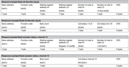
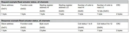
2.2 Frame format: Read Discrete Input
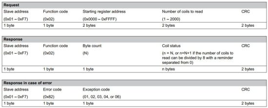
Example:
2.3 Frame format: Read Holding Registers

Example:


2.4 Frame format: Read Input Registers

Example:


2.5 Frame format: Write Single Coil

Example:

2.6 Frame format: Write Single Holding Register

Examples:


2.7 Frame format: Write Multiple Coils

Example:

2.8 Frame format: Write Multiple Holding Registers

Example:

3 Available variables
These variables are available when communicating with the Base PRO controller (with the Modbus RTU compatible software installed).
3.1 Temperature conversion
Note
If no data value is availabe the celcius value is set to 1802.6.
The Uponor Smatrix Base PRO controller uses Fahrenheit (default) to read and calculate temperatures. The temperature format can be changed in the U_BMS.txt file.
To convert the data value into celcius, use the following mathematical formula.
Celcius = ((data value – 320)/1.8)/10
Temperature (absolute value)

Temperature (relative value)

Humidity (absolute value)

3.2 Controller limitations
Cooling state
An ordinary Base PRO system (with touch screen, not connected to a BMS) uses an offset temperature to adjust the setpoints when switching between heating and cooling. This setting is only available via the touch screen interface (I-167), which is not installed when connected to a BMS.
When connected to a BMS, and the heating/cooling state is set to cooling, the cooling offset is set to 2 °C (2 °F), leaving the zone setpoints to be changed by the BMS.
ECO state
If the Base PRO system is set to ECO state the controller applies an ECO setback value of 4 °C (4 °F) to the setpoints (which is shown in the thermostats).
When the BMS reads the setpoint, when in ECO state, it will receive the actual setpoint (without the ECO setback value applied).

Zones
Caution!
When writing to a channel, address the lowest channel number (master channel) in the zone (if more chan one channel in the zone) in order to change the value/state for the whole zone.
The Base PRO controller can control a maximum of 6 actuator channels, 12 if a slave module is installed. These channels are then divided into zones which are linked to a thermostat.
A zone can consist of 1 to 12 channels, and not all channels must be connected to an actuator and linked to a thermostat.
Comfort setting
The Base PRO can set a basic level of comfort for a zone when there is no demand for heating. The value set is the percentage of time the actuators are opened.
It will shorten the heat up time for the room, which is useful in rooms where other heating sources, e.g. a fireplace, is present.
When the BMS reads the comfort setting it will recieve the actual percentage.
Max/min limitations
If the BMS writes a setpoint to a zone, the Base PRO controller applies maximum and minimum limitations before checking if there is a demand for heating or cooling. The limited setpoint is also shown on the thermostat.
The maximum and minumlimitations are also affected whether the controller is set to Comfort or ECO state.
When the BMS reads the setpoint it will recieve the actual setpoint (without limitation applied).

3.3 Coil data points


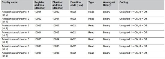
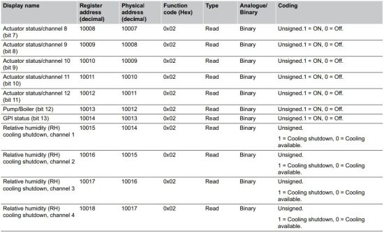
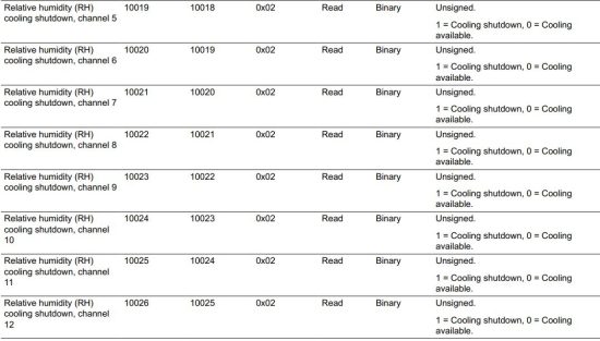
3.4 Discrete Input data points
These datapoints are read only and show the actuator, pump/boiler, and GPI status on the controller (binary, on/off).
3.5 Input Register data points


3.6 Holding Register data points
Note
All temperature data is sent in tenths of either Celsius or Fahrenheit, depending on the setting in U_BMS file.
Note
0x7FFF is returned if no data is available for the channel.
These datapoints can be both read or written, and contain temperature setpoint and max/min temperature limits for each channel (1 to 12) on the controller.


4 Troubleshooting
In case of problems and alarms in the Uponor Smatrix Base PRO system, check the table below.
Otherwise see Uponor Smatrix Base PRO installation and operation manual section 16 for more information.
4.1 No communication between
controller and BMS
Changes done in BMS are not carried out in the controller and/or thermostats
- Missing U_BMS.txt file
– Download the file from the Uponor website and copy it onto the microSD card
• U_BMS.txt file not configured correctly
– Configure the U_BMS.txt file correctly See Preparation, Page 3 step 3, for more information
• Incorrect software version in the controller
– Install the correct software in the controller See Preparation, Page 3 step 2, for more information
• Disconnected communication cable
– Check all wiring to make sure all communication cables are connected correctly
4.2 Slow communication, or high latency, between Uponor system and BMS
It takes a long time for Uponor parameters to change in the after being sent from the BMS
• The Uponor Smatrix Base PRO Interface I-147 is installed and registered in the system
– Unregister and disconnect the interface from the Uponor system
4.3 Wrong parameters changed in Uponor system compared to BMS settings
Wrong parameters are changed in the Uponor system after new values are sent from the BMS
• The Uponor Smatrix Base PRO Interface I-147 is installed and registered in the system
– Unregister and disconnect the interface from the Uponor system
Uponor GmbH
Industriestraße 56,
D-97437 Hassfurt, Germany
1090255 v5_08_2024_EN
Production: Uponor/SDE
Uponor reserves the right to make changes, without prior notification, to the specification of incorporated components in line with its policy of continuous improvement and development.

Read More About This Manual & Download PDF:
Documents / Resources
 |
uponor X-148 Smatrix Base PRO Controller [pdf] Instruction Manual X-148 Smatrix Base PRO Controller, X-148, Smatrix Base PRO Controller, Base PRO Controller, Controller |


