unitronics UG EX-A2X Input-Output Expansion Module Adapter

Introduction
The EX-A2X interfaces between a variety of I/O expansion modules and specific Unitrans’s’ OPLCs.
A single adapter can be connected to up to 8 expansion modules.
The EX-A2X may either be snap-mounted on a DIN rail, or screw-mounted onto a mounting plate.
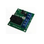
Component identification

- Status indicators
- COM port, EX-A2X to OPLC
- Power supply connection points
- EX-A2X to expansion module connection port
- Before using this product, it is the responsibility of the user to read and understand this document and any accompanying documentation.
- All examples and diagrams shown herein are intended to aid understanding, and do not guarantee operation. Unitronics accepts no
responsibility for actual use of this product based on these examples. - Please dispose of this product in accordance with local and national standards and regulations.
- Only qualified service personnel should open this device or carry out repairs.
User safety and equipment protection guidelines
This document is intended to aid trained and competent personnel in the installation of this equipment as defined by the European directives for machinery, low voltage, and EMC. Only a technician or engineer trained in the local and national electrical standards should perform tasks associated with the device’s electrical wiring.
Symbols are used to highlight information relating to the user’s personal safety and equipment protection throughout this document. When these symbols appear, the associated information must be read carefully and understood fully.
|
Symbol |
Meaning |
Description |
 |
Danger |
The identified danger causes physical and property damage |
 |
Warning |
The identified danger can cause physical and property damage |
|
Caution |
Caution |
Use caution. |
|
|
|
|
Environmental Considerations
|
▪ Do not install in areas with: excessive or conductive dust, corrosive or flammable gas, moisture or rain, excessive heat, regular impact shocks or excessive vibration. |
|
|
UL Compliance
The following section is relevant to Unitrans’s’ products that are listed with the UL.
The following models: IO-AI4-AO2, IO-AO6X, IO-ATC8, IO-DI16, IO-DI16-L, IO-DI8-RO4, IO-DI8-RO4-L, IO-DI8-TO8, IO-DI8-TO8-L, IO-RO16, IO-RO16-L, IO-RO8, IO-RO8L, IO-TO16, EX-A2X are UL listed for Hazardous Locations.
The following models: EX-D16A3-RO8, EX-D16A3-RO8L, EX-D16A3-TO16, EX-D16A3-TO16L, IO-AI1X-AO3X, IO-AI4-AO2, IO-AI4-AO2-B, IO-AI8, IO-AI8Y, IO-AO6X, IO-ATC8, IO-D16A3-RO16, IO-D16A3-RO16L, IO-D16A3-TO16, IO-D16A3-TO16L, IO-DI16, IO-DI16-L, IO-DI8- RO4,
IO-DI8-RO4-L, IO-DI8-RO8, IO-DI8-RO8-L, IO-DI8-TO8, IO-DI8-TO8-L, IO-DI8ACH, IO-LC1, IO-LC3, IO-PT4, IO-PT400, IO-PT4K, IO-RO16, IO-RO16-L, IO-RO8, IO-RO8L, IO-TO16, EX-A2X, EX-RC1 are UL listed for Ordinary Location.
UL Ratings, Programmable Controllers for Use in Hazardous Locations,
Class I, Division 2, Groups A, B, C and D
These Release Notes relate to all Unitrans’s products that bear the UL symbols used to mark products that have been approved for use in hazardous locations, Class I, Division 2, Groups A, B, C and D.
|
Caution |
|
Relay Output Resistance Ratings
The products listed below contain relay outputs:
Input/Output expansion modules, Models: IO-DI8-RO4, IO-DI8-RO4-L, IO-RO8, IO-RO8L
- When these specific products are used in hazardous locations, they are rated at 3A res, when these specific products are used in nonhazardous environmental conditions, they are rated at 5A res, as given in the product’s specifications.
Mounting the Module
DIN-rail mounting
Snap the device onto the DIN rail as shown below; the module will be squarely situated on the DIN rail.

Screw-Mounting
The following figure is not drawn to scale. Mounting screw type: either M3 or NC6-32.

Connecting the OPLC to the EX-A2X
Use the communication cable to connect the module’s PLC expansion port to the PLC.
Take care to connect the correct cable. The connectors of this cable are housed in yellow insulation. Note that one end is marked To PLC and the other To Adapter; insert accordingly.
The module is supplied with a 1-meter cable, part number EXL-CAB100. Other cable lengths are also available.
Use only an original Unitronics cable and do not make any changes to it.

Connecting Expansion Modules
An adapter provides the interface between the OPLC and an expansion module. To connect the I/O module to the adapter or to another module:
- Push the module-to-module connector into the port located on the right side of the device.
Note that there is a protective cap provided with the adapter. This cap covers the port of the final I/O module in the system.
- To avoid damaging the system, do not connect or disconnect the device when the power is on.
Component identification
- Module-to-module connector
- Protective cap

Wiring
|
|
|
|
Wiring Procedures
Use crimp terminals for wiring; use 26-12AWG wire (0.13 mm 2–3.31 mm2 ) for all wiring purposes
- Strip the wire to a length of 7±0.5mm (0.250–0.300 inches).
- Unscrew the terminal to its widest position before inserting a wire.
- Insert the wire completely into the terminal to ensure that a proper connection can be made.
- Tighten enough to keep the wire from pulling free.
- To avoid damaging the wire, do not exceed a maximum torque of 0.5 Nm (5 kgfcm).
- Do not use tin, solder, or any other substance on stripped wire that might cause the wire strand to break.
- Install at maximum distance from high-voltage cables and power equipment.
Wiring Power Supply
- Connect the “positive” cable to the “+V” terminal, and the “negative” to the “0V” terminal.
- Always connect the functional earth pin to the earth ground. Use a dedicated wire for this purpose; it must not exceed 1 meter.
- Do not connect the neutral or line signal of the 110/220VAC to the device’s 0V pin.
- In the event of voltage fluctuations or non-conformity to voltage power supply specifications, connect the device to a regulated power supply.
- A non-isolated power supply can be used provided that a 0V signal is connected to the chassis.
- Note that both the OPLC and the EX-A2X must be connected to the same power supply.
The EX-A2X and the OPLC must be turned on and off simultaneously.

Technical Specifications
| I/O module capacity | Up to 8 I/O modules can be connected to a single adapter. |
| Power supply | 12VDC or 24VDC |
| Permissible range | 10.2 to 28.8VDC |
| Max. current consumption | 650mA @ 12VDC; 350mA @ 24VDC |
| Typical power consumption | 4W |
| Current supply for I/O modules Galvanic isolation | 1A max. from 5V (see Note 1) |
| EX-A2X power supply to: | |
| OPLC port | Yes |
| Expansion module port | No |
| Status indicators | |
| (PWR) | Green LED—Lit when power is supplied |
| (COMM.) | Green LED—Lit when communication is established. |
| Environmental | IP20/NEMA1 |
| Operating temperature | 0° to 50° C (32 to 122°F) |
| Storage temperature | -20° to 60° C (-4 to 140°F) |
| Relative Humidity (RH) | 10% to 95% (non-condensing) |
| Dimensions (WxHxD) | 80mm x 93mm x 60mm (3.15” x 3.66” x 2.362”) |
| Weight | 125g (4.3oz.) |
| Mounting | Either onto a 35mm DIN-rail or screw- mounted. |
Notes:
- Example: 2 I/O-DI8-TO8 units consume a maximum of 140mA of the 5VDC supplied by the EX-A2X.
Addressing I/Os on Expansion Modules
Inputs and outputs located on I/O expansion modules that are connected to an OPLC are assigned addresses that comprise a letter and a number. The letter indicates whether the I/O is an input (I) or an output (O). The number indicates the I/O’s location in the system. This number relates to both the position of the expansion module in the system, and tothe position of the I/O on that module.
Expansion modules are numbered from 0-7 as shown in the figure below.

The formula below is used to assign addresses for I/O modules used in conjunction with the OPLC.
X is the number representing a specific module’s location (0-7). Y is the number of the input or output on that specific module (0-15).
The number that represents the I/O’s location is equal to:
32 + x • 16 + y
Examples
- Input #3, located on expansion module #2 in the system, will be addressed as I 67, 67 = 32 + 2 • 16 + 3
- Output #4, located on expansion module #3 in the system, will be addressed as O 84, 84 = 32 + 3 • 16 + 4.
EX90-DI8-RO8 is a stand-alone I/O module. Even if it is the only module in the configuration, the EX90-DI8-RO8 is always assigned the number 7.
Its I/Os are addressed accordingly.
Example
- Input #5, located on an EX90-DI8-RO8 connected to an OPLC will be addressed as I 149, 149 = 32 + 7 • 16 + 5
The information in this document reflects products at the date of printing. Unitrans’s reserves the right, subject to all applicable laws, at any time, at its sole discretion, and without notice, to discontinue or change the features, designs, materials and other specifications of its products, and to either permanently or temporarily withdraw any of the forgoing from the market
All information in this document is provided “as is” without warranty of any kind, either expressed or implied, including but not limited to any implied warranties of merchantability, fitness for a particular purpose, or non-infringement. Unitrans’s assumes no responsibility for errors or omissions in the information presented in this document. In no event shall Unitrans’s be liable for any special, incidental, indirect or consequential damages of any kind, or any damages whatsoever arising out of or in connection with the use or performance of this information.
The tradenames, trademarks, logos and service marks presented in this document, including their design, are the property of Unitrans’s (1989) (R”G) Ltd. or other third parties and you are not permitted to use them without the prior written consent of Unitrans’s or such third party as may own them.
Documents / Resources
 |
unitronics UG EX-A2X Input-Output Expansion Module Adapter [pdf] User Guide UG EX-A2X Input-Output Expansion Module Adapter, UG EX-A2X, Input-Output Expansion Module Adapter, Expansion Module Adapter, Module Adapter, Adapter |