![]() M30X Series
M30X Series
UHF RFID Module 
Module Specification
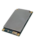
M-301 UHF RFID Module
1. Product View
| M-301 | 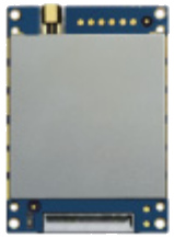 |
▪ RF Channel: | Single Channel |
| ▪ RF Connector: | MMCX | ||
| ▪ Antenna Connection Mode : | Single Antenna | ||
| ▪ Interface Connector: | FH34SRJ-30S-0.5SH(50) | ||
| ▪ RF Connectors Material: | Gold-plated brass | ||
| ▪ PCB Material: | Rogers FR4 gold-plated | ||
| ▪ Shield Material: | Cupronickel |
2. Module Dimensions ( unit: mm )

3. Kit Dimensions ( unit: mm )

Note: Dimensional drawings are three-dimensional renderings, not physical.
Module Specification
M-302 UHF RFID Module
1. Product View
| M-302 | 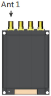 |
▪ RF Channel: | Four channels |
| ▪ RF Connector: | SMA | ||
| ▪ Antenna Connection Mode : | Four Antenna | ||
| ▪ Interface Connector: | Molex 53261-1571 | ||
| ▪ RF Connectors Material: | Gold-plated brass | ||
| ▪ PCB Material: | Rogers FR4 gold-plated | ||
| ▪ Shield Material: | Aluminum |
2. Module Dimensions ( unit: mm )

3. Kit Dimensions ( unit: mm )

Note: Dimensional drawings are three-dimensional renderings, not physical.
Module Specification
M-303 UHF RFID Module
1. Product View
| M-303 | 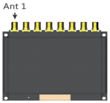 |
▪ RF Channel: | Eight Channels |
| ▪ RF Connector: | SMA | ||
| ▪ Antenna Connection Mode : | Eight Antenna | ||
| ▪ Interface Connector: | Molex 53261-1571 | ||
| ▪ RF Connectors Material: | Gold-plated brass | ||
| ▪ PCB Material: | Rogers FR4 gold-plated | ||
| ▪ Shield Material: | Aluminum |
2. Module Dimensions ( unit: mm )

3. Kit Dimensions ( unit: mm )

Note: Dimensional drawings are three-dimensional renderings, not physical.
Module Specification
M-304 UHF RFID Module
1. Product View
| M-304 | 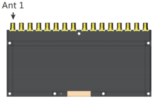 |
▪ RF Channel: | Sixteen channels |
| ▪ RF Connector: | SMA | ||
| ▪ Antenna Connection Mode : | Sixteen Antenna | ||
| ▪ Interface Connector: | Molex 53261-1571 | ||
| ▪ RF Connectors Material: | Gold-plated brass | ||
| ▪ PCB Material: | Rogers FR4 gold-plated | ||
| ▪ Shield Material: | Aluminum |
2. Module Dimensions ( unit: mm )

3. Kit Dimensions ( unit: mm )

Note: Dimensional drawings are three-dimensional renderings, not physical.
Module Specification
UHF RFID Module
PIN Connector Pin Assignments
| PIN Connector Pin Assignments | ||
 Connector (15Pin , Space between PINs 1.25mm) Connector (15Pin , Space between PINs 1.25mm) |
||
| PIN | Interface | Instruction |
| 1 | GND | Meanwhile grounding |
| 2 | GND | |
| 3 | 4.5V – 5.5V DC | Meanwhile connect power, Recommended input voltage: 4.6V |
| 4 | 4.5V – 5.5V DC | |
| 5 | GPIO 3 | Output |
| 6 | GPIO 4 | Output |
| 7 | GPIO 1 | Input |
| 8 | Beeper | Has driven with > 50mA output current |
| 9 | UART_RXD | TTL level |
| 10 | UART_TXD | |
| 11 | USB_DM | For testing |
| 12 | USB_DP | |
| 13 | GPIO 2 | Input |
| 14 | EN | High level enable |
| 15 | GPIO 5 | RS-485 direction control |
Module Specification
UHF RFID Module
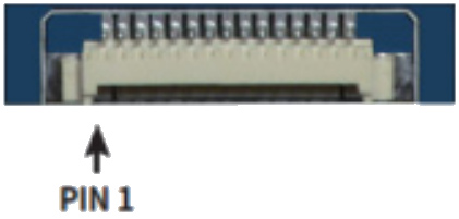
| PIN Connector Pin Assignments | ||
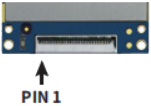 FPC connector (30Pin , Space between PINs 0.5mm) FPC connector (30Pin , Space between PINs 0.5mm) |
||
| PIN | Interface | Instruction |
| 1 | GND | Meanwhile grounding |
| 2 | GND | |
| 3 | GND | |
| 4 | GND | |
| 5 | GND | |
| 6 | 4.5V–5.5V DC | Meanwhile connect power, Recommended input voltage: 4.8V |
| 7 | 4.5V–5.5V DC | |
| 8 | 4.5V–5.5V DC | |
| 9 | 4.5V–5.5V DC | |
| 10 | 4.5V–5.5V DC | |
| 11 | 4.5V–5.5V DC | |
| 12 | 4.5V–5.5V DC | |
| 13 | 4.5V–5.5V DC | |
| 14 | 4.5V–5.5V DC | |
| 15 | 4.5V–5.5V DC | |
| 16 | GND | Meanwhile grounding |
| 17 | GND | |
| 18 | GND | |
| 19 | GND | |
| 20 | GND | |
| 21 | UART_RXD | TTL level |
| 22 | UART_TXD | |
| 23 | EN | High level enable |
| 24 | GPIO1 | Input |
| 25 | Beeper | Has driven with > 50mA output current |
| 26 | GPIO3 | Output |
| 27 | GPIO4 | Output |
| 28 | GPIO5 | RS-485 direction control |
| 29 | GND | Meanwhile grounding |
Module Specification
UHF RFID Module
Electrical Characteristics
| Electrical Characteristics | |||||
| Operating Voltage | 4.5V – 5.5V | ||||
| Standby Mode Current | 50mA | ( EN high level ) | |||
| Sleep Mode Current | <100uA | ( EN high level ) | |||
| Operating Current | Conditions | Min | Type | Max | |
| @5V( 33dbm Output,Multi-tag,25°C ) | 300mA | 1.3A+-10% | 2.5A | ||
| Operating Temperature | – 20 °C ~ + 65 °C | ||||
| Storage Temperature | – 40 °C ~ + 85 °C | ||||
| Humidity | 5%RH~95%RH (non -condensing) | ||||
| Air Interface Protocol | EPC global UHF Class 1 Gen 2 / ISO 18000-6C | ||||
| Spectrum Range | 902MHz – 928MHz,865MHz – 868MHz | ||||
| Supported Regions | US, Canada and other regions following U.S. FCC Europe and other regions following ETSI EN 302 208 China , Korea , Malaysia |
||||
| Output Power | 0 – 33dBm | ||||
| Output Power Precision | +/- 1dB | Note: • When the temperature, measured by the ambient temperature measurement function, exceeds 60°C, please do not keep the device working at full capacity. • Please connect the device to heat sink when it continuously work at full load. • Supply voltage must not exceed 5.5V,otherwise it will damage the internal protection circuit. • Be cautious if set RF output power over 30dBm, as the peak current and internal temperature will increase significantly. |
|||
| Output Power Flatness | +/- 0.2dB | ||||
| Receive Sensitivity | < -88 dBm | ||||
| Peak Inventory Speed | >900 tags/sec | ||||
| Tag RSSI | Supported | ||||
| Antenna Detector | Supported | ||||
| Ambient Temp Monitor | Supported | ||||
| Working Mode | Single/DRM | ||||
| Host Communication | Uart 3.3V | ||||
| GPIO | 2 inputs & 2 outputs(3.3V level) | ||||
| Max Baud Rate | 38400 bps ,115200 bps ( Default and recommended ),921600bps | ||||
| Heat Dissipation | External radiator | ||||
FCC WARNING:
Any Changes or modifications not expressly approved by the party responsible for compliance could void the user’s authority to operate the equipment.
This device complies with part 15 of the FCC Rules. Operation is subject to the following two conditions: (1) This device may not cause harmful interference, and (2) this device must accept any interference received, including interference that may cause undesired operation.
This equipment has been tested and found to comply with the limits for a Class B digital device, pursuant to part 15 of the FCC Rules. These limits are designed to provide reasonable protection against harmful interference in a residential installation. This equipment generates uses and can radiate radio frequency energy and, if not installed and used in accordance with the instructions, may cause harmful interference to radio communications. However, there is no guarantee that interference will not occur in a particular installation. If this equipment does cause harmful interference to radio or television reception, which can be determined by turning the equipment off and on, the user is encouraged to try to correct the interference by one or more of the following measures:
- Reorient or relocate the receiving antenna.
- Increase the separation between the equipment and receiver.
- Connect the equipment into an outlet on a circuit different from that to which the receiver is connected.
- Consult the dealer or an experienced radio/TV technician for help.
FCC RF EXPOSURE STATEMENT:
This equipment complies with FCC radiation exposure limits set forth for an uncontrolled environment.
This transmitter must not be co-located or operating in conjunction with any other antenna or transmitter.
This equipment should be installed and operated with minimum distance 20cm between the radiator& your body.
Integration instructions for host product manufacturers according to KDB 996369 D03 OEM
Manual v01
2.2 List of applicable FCC rules
CFR 47 FCC PART 15 SUBPART C has been investigated. It is applicable to the modular.
2.3 Specific operational use conditions
This module is stand-alone modular. If the end product will involve the Multiple simultaneously transmitting condition or different operational conditions for a stand-alone modular transmitter in a host, host manufacturer have to consult with module manufacturer for the installation method in end system.
2.4 Limited module procedures
Not applicable
2.5 Trace antenna designs
Not applicable
2.6 RF exposure considerations
To maintain compliance with FCC’s RF Exposure guidelines, This equipment should be installed and operated with minimum distance of 20cm from your body.
2.7 Antennas
This radio transmitter FCC ID: 2AKQD-M-302 has been approved by Federal Communications Commission to operate with the antenna types listed below, with the maximum permissible gain indicated. Antenna types not included in this list that have a gain greater than the maximum gain indicated for any type listed are strictly prohibited for use with this device.
| No. | Antenna Type | Antenna Gain | Impedance | Frequency Range |
| 1 | external antenna | 2.0dBi | 50Ω | 902-928MHz |
2.8 Label and compliance information
The final end product must be labeled in a visible area with the following” Contains
FCC ID: 2AKQD-M-302”
2.9 Information on test modes and additional testing requirements
Host manufacturer is strongly recommended to confirm compliance with FCC requirements for the transmitter when the module is installed in the host.
2.10 Additional testing, Part 15 Subpart B disclaimer
Host manufacturer is responsible for compliance of the host system with module installed with all other applicable requirements for the system such as Part 15 B
![]()
Documents / Resources
 |
unitech M30X Series UHF RFID Module [pdf] Instructions M-301, M-302, M-303, M-304, M30X Series UHF RFID Module, M30X Series Module, UHF RFID Module, RFID Module, UHF Module, Module |