UNI-T UTG4000A Function/Arbitrary Waveform Generator
Product Info
Introduction
Dear Users:
Hello! Thank you for choosing this brand new UNI-T device. In order to safely and correctly use this instrument, please read this manual thoroughly, especially the Safety Notes part.
After reading this manual, it is recommended to keep the manual at an easily accessible place, preferably close to the device, for future reference
Copyright Information
● UNl-T Uni-Trend Technology (China) Limited. All rights reserved.
Trademark Information
● UNI-T is the registered trademark of Uni-Trend Technology (China) Limited.
Document Version
UTG4000A-20160618-EN-V1.2
Statement
● UNI-T products are protected by patent rights in China and foreign countries, including issued and pending patents.
● UNI-T reserves the rights to any product specification and pricing changes.
● UNI-T reserves all rights. Licensed software products are properties of Uni-Trend and its subsidiaries or suppliers, which are protected by national copyright laws and international treaty provisions.
● Information in this manual supercedes all previously published versions.
Warranty
UNI-T warrants that the product will be free from defects for a three-year period. If the product is re-sold, the warranty period will be from the date of the original purchase from an authorized UNI-T distributor. Probes, other accessories, and fuses are not included in this warranty.
If the product is proved to be defective within the warranty period, UNI-T reserves the rights to either repair the defective product without charging of parts and labor, or exchange the defected product to a working equivalent product. Replacement parts and products may be brand new, or perform at the same specifications as brand new products. All replacement parts, modules, and products become the property of UNI-T.
The “customer” refers to the individual or entity that is declared in the guarantee. In order to obtain the warranty service, “customer” must inform the defects within the applicable warranty period to UNI-T, and to perform appropriate arrangements for the warranty service. The customer shall be responsible for packing and shipping the defective products to the designated maintenance center of UNI-T, pay the shipping cost, and provide a copy of the purchase receipt of the original purchaser. If the product is shipped domestically to the location of the UNI-T service center, UNI-T shall pay the return shipping fee. If the product is sent to any other location, the customer shall be responsible for all shipping, duties, taxes, and any other expenses. This warranty shall not apply to any defects or damages caused by accidental, machine parts’ wear and tear, improper use, and improper or lack of maintenance. UNI-T under the provisions of this warranty has no obligation to provide the following services:
a) Any repair damage caused by the installation, repair, or maintenance of the product by non UNI-T service representatives. b) Any repair damage caused by improper use or connection to an incompatible device. c) Any damage or malfunction caused by the use of a power source which does not conform to the requirements of this manual.
d) Any maintenance on altered or integrated products (if such alteration or integration leads to an increase in time or difficulty of product maintenance). This warranty written by UNI-T for this product, and it is used to substitute any other express or implied warranties. UNI-T and its distributors do not offer any implied warranties for merchantability or applicability purposes.
For violation of this guarantee, UNI-T is responsible for the repair or replacement of defective products is the only remedy available to customers. Regardless of whether UNI-T and its distributors are informed that any indirect, special, incidental, or consequential damage may occur, the UNI-T and its distributors shall not be responsible for any of the damages.
Safety Information
1.1 Safety Terms and Symbols
The following terms may appear in this quick guide:
Warning: The conditions and behaviors may endanger life.
Caution: The conditions and behaviors may cause damage to the product and other properties.
The following terms may appear on the product:
Danger: Performing this operation may cause immediate damage to the operator.
Warning: This operation may cause potential damage to the operator.
Caution: This operation may cause damage to the product and devices connected to the product.
General Safety Overview
This instrument is designed and produced in strict accordance with GB4793 Safety Requirements for Electronic Measuring Apparatus and IEC61010-1 safety standard, up to insulation and overvoltage standard CAT II 300V and safety standard for level-II pollution.
Please read the following preventive safety measures:
● In order to prevent electric shock or fire, please use power line and adapter dedicated to this product and approved by the country.
● This product is grounded through protective ground lead in the power line. In order to prevent electric shock, please check whether the power socket to be used for the product is grounded. Please ensure that the protective ground terminal of the product is reliably connected to the ground terminal of power line before connecting any input or output terminal other than power line.
● To avoid personal injury and prevent damage to the product or any product connected to the product. In order to avoid possible danger, the product can only be used in the specified scope. Only personnel that have received professional training can execute maintenance procedures.
● In order to prevent fire or electric shock, please pay attention to all rated values and signs of the product. Please read the user manual to further understand information about rated value.
● Don’t use input voltage above rated value of the instrument.
● Inspect whether accessories suffer from mechanical damage before use. If so, please replace them.
● Only accessories provided for the product can be used. Please don’t use accessories that are damaged.
● Don’t insert metal objects into input or output terminal of the product.
● If you suspect the product is damaged, please ask qualified maintenance personnel for inspection.
● Please don’t put the product into operation when crate is opened.
● Please don’t operate in humid environment.
● Please don’t operate in inflammable and explosive environment.
● Keep the surface of product clean and dry.
Quick Start
General Inspection
When you get a new function/arbitrary waveform generator, you are advised to inspect the instrument according to the following steps.
Inspect Whether Damage is Caused by Transportation
If the packaging box or foamed plastic supplementary mat is seriously damaged, please contact with dealer of the product or local office.
If the instrument is damaged during transportation, please keep the package, and notify transportation department and dealer of the product, who will arrange repair or replacement.
Inspect Accessories
UTG4000A accessories include power line (applicable to the destination country/region), a USB data transmission line, two BNC cables (1m), a user CD and a product warranty card.
In case of lack or damage of accessories, please contact with dealer of the product or local office.
Inspect Complete Machine
If appearance of the instrument is damaged, the instrument runs abnormally or fails to pass performance test, please contact with dealer of the product or local office.
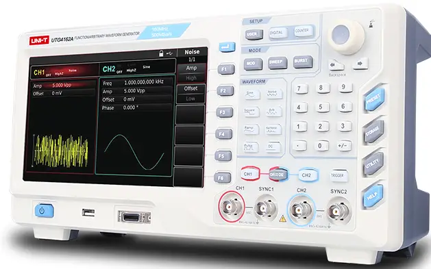
Introduction of Panels and Keys
Front Panel
Function/arbitrary waveform generator of UTG4000A series provides users with simple and intuitive front panel that is easy to operate, which is shown in figure 2-1 below:

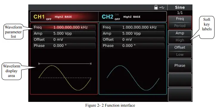
Function Interface
Function interface is shown in Figure 2-2:
Back Pane

1 Output Basic Waveform
2.3.2 Set Output Frequency
The default configuration of waveform is a sine wave with frequency of 1kHz and peak-to-peak amplitude of 100mV (terminating at 50Ω) when powering on. One example for changing frequency into 2.5MHz are as follows:
1. Press function key F1, when outline border in the display area is the color of corresponding channel, and “Freq” character is white, “Period” tag is gray. If the current frequency value is valid, the same frequency is used. Please press function key F1 again to change to the set waveform period, when “Freq” character turns gray, “Period” character is highlighted, and frequency and period can be switched.
Set Output Amplitude
The default configuration of waveform is a sine wave with peak-to-peak amplitude of 100mV (terminating at 50Ω) when powering on. The specific steps for changing amplitude into 300mVpp are as follows:
1. Press function key F2, when outline border of corresponding part in the display area is the color of corresponding channel, and character “Amp” is white, tag “High” is gray. If the current amplitude value is valid when changing amplitude, the same amplitude is used. Press function key F2 again to quickly switch between units Vpp, Vrms, and dBm.
2. Input requires amplitude value 300 with numeric keyboard.
3. Select required unit
Press soft key of corresponding unit. The waveform generator outputs waveform with the displayed amplitude when you select unit (if output has been used). Press mVpp in this example.
Note: this parameter can also be set with multi-functional knob and direction keys.
Set DC Offset Voltage
The default configuration of waveform is a sine wave with DC offset voltage of 0V (terminating at 50Ω) when powering on. The specific steps for changing DC offset voltage into -150mV are as follows:
1. Press function key F3, when outline border of corresponding part in the display area is the color of corresponding channel. If the current DC offset value is valid when changing DC offset, the same DC offset value is used. Press function key F3 again and you will find that the waveform of parameter described with amplitude and DC offset has been described with high level (maximum value) and low level (minimum value). Such method for setting signal limit is very convenient for digital application.
2. Input required DC offset value -150mV with numeric keyboard
3. Select required unit
Press soft key of corresponding unit. The waveform generator outputs waveform with the displayed DC offset when you select unit (if output has been used). Press mV in this example.
Note: this parameter can also be set with multi-functional knob and direction key.
Fault Handling
Possible faults in use of UTG4000A and troubleshooting methods are listed below. If these faults occur, please handle them according to corresponding steps. If they cannot be handled, please contact with the dealer or local office, and provide the information about your machine (method: press Utility and System successively).
No Display on Screen (Blank Screen)
If the signal generator still does not display after pressing power switch on front panel
1) Inspect whether power source is connected well.
2) Inspect whether power switch on back panel is connected well at “I”.
3) Whether power switch on front panel is connected well.
4) Restart the instrument.
5) If the product still cannot be used normally, please contact with the dealer or local office and let us serve you.
No Waveform Output
Setting is correct but no waveform is output
1) Inspect whether BNC cable and channel output terminal are connected correctly.
2) Inspect whether CH1 or CH2 is turned on.
3) If the product still cannot be used normally, please contact with the dealer or local office and let us serve you.
Fail to Correctly Recognize U Disk
1) Inspect whether U disk works normally.
2) Ensure that Flash U disk is used. The instrument does not support hard disk.
3) Restart the instrument, and insert U disk again to see whether it works normally.
4) If U disk still cannot be correctly recognized, please contact with the dealer or local office and let us serve you.
Contact
Manufacturer:
Uni-Trend Technology (China) Limited No 6, Gong Ye Bei 1st Road
Songshan Lake National High-Tech Industrial Development Zone, Dongguan City Guangdong Province China
Postal Code: 523 808
Headquarters:
Uni-Trend Group Limited Rm901, 9/F, Nanyang Plaza 57 Hung To Road
Kwun Tong
Kowloon, Hong Kong
Tel: (852) 2950 9168
Fax: (852) 2950 9303
Email: info@uni-trend.com
http://www.uni-trend.com
Documents / Resources
 |
UNI-T UTG4000A Function/Arbitrary Waveform Generator [pdf] User Guide UTG4000A Function Arbitrary Waveform Generator, UTG4000A, Function Arbitrary Waveform Generator, Arbitrary Waveform Generator, Waveform Generator, Generator |