
Contents
hide
WF WE-CLFS Line Filters Passive Components Owner’s Manual
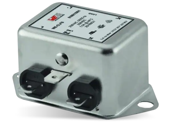
1. Single Phase Line Filter

2. Internal Schematic

3. General Information
Rated current of the mains filter :
Must be equal to or greater than the current requirements of the connected devices.
For ambient temperatures above 40 °C, the following derating curve applies.

4. ATTENUATION FOR DIFFERENT INDUCTANCE VALUES AND TOPOLOGIES:


Attenuation plots for the examined filters with system impedances of 50 Ω and 50 Ω. You can simulate these plots and many more with our REDEXPERT online tool.
5. Influence of the System Impedances

6. Filter Selection with REDEXPERT
Selection Guide:
- Choose rated current
- Check frequency range of the noise
- Check attenuation in this frequency range
- Choose maximal allowed leakage current
Take the different system impedances in consideration.

7. Interesting: Leakage Current

For low leakage requesting applications, we offer a low leakage version without Y capacitors.
8. Placement and Grounding

Read More About This Manual & Download PDF:
Documents / Resources
 |
WF WE-CLFS Line Filters Passive Components [pdf] Owner's Manual WE-CLFS Line Filters Passive Components, WE-CLFS, Line Filters Passive Components, Filters Passive Components, Passive Components, Components |


