ubicquia APAI Ubihub Simply Connected Simply
Smart Installation Guide

Product Overview
1.1 View of UbiHub parts from top

1.2 View of UbiHub parts from bottom

1.3 Package Contents
- UbiHub Unit (with open cap attached)
- Mounting Clamp
- Mounting Clamp Inserts (additional)
- Dual-Camera
- Grounding Cable
1.4 Required Tools (Not Included)
- 3/16” Hex bit driver / Wrench
- Standard Screwdriver or 5/16” Socket for grounding screw
- Deep drive ½” Socket
- Torque driver (capable of at min 40.in lb)
- Grounding clamp, lug, or extra length of grounding cable as needed
- Safety Tether (for ensuring device safety during installation)
Unpacking the UbiHub
2.1 Open the top of the packaging as indicated on the outside of the box. Do not remove the UbiHub from the box at this time.

2.2 Ensure that all items listed in the package contents (ref 1.2) are included in the box. If any item is missing, e-mail support@ubicquia.com or call 1.954.678.6191 (Monday through Friday 9am to 5pm EST).

2.3 Remove the mounting clamp from foam insert and unwrap the protective film. Caution: DO NOT remove the UbiHub from the box yet.
Preinstall Clamp
3.1 Measure and Preinstall Clamp The clamp fits a 2.3/8” (60.3 mm) diameter pole, with optional replacement inserts to accommodate for a smaller pole diameter, and can be adjusted between 6.04” – 10.57” (153.5-268.6 mm) for horizontal travel along the device, and between 1 7/8” – 3 7/8” (49-99mm) vertical travel to accommodate pole distance.

3.2 Mounting Clamp
The mounting clamp has inserts available to fit 1.25” diameter pole arms.
Without inserts, the mounting clamp fits poles that are 2.3/8” in diameter.
*Contact Ubicquia if you require a clamp insert, but did not receive a set.


3.3 OPTIONAL: Measure the distance from the NEMA socket to the closest point on the pole that will allow for the Ubihub to be seated
level to the luminaire.

NOTE: Record position horizontal and vertical dimensions on UbiHub and clamp for later use in multiple installations of the same luminaire type.
3.4 Use a 3/16” Hex bit driver to unscrew and remove the clamp adjustment cover from the clamp. Discard as this piece is no longer needed.

3.5 Align the shuttles on the top of the clamp with the rail openings on the bottom of the UbiHub housing while still in the box. There is a single orientation for assembly.

3.6 Slide the clamp along the housing rails and hand-tighten into position for now.

NOTE: If clamp placement was premeasured, or if installing multiple units on the same luminaire type, set the clamp position using the reference dimensions on both the housing and clamp, then tighten all adjustment bolts to 40 in-lbs torque.
3.7 Open the clamp with the swivel locking nut up out of the way. If your pole arm is smaller than 2.3/8” (60.3 mm), you will install a clamp insert set into the clamp. Clamp inserts are available in 1.25” sizes, and come as a set of two. The inserts are clearly marked with a numeral 1 or 2, denoting the top clamp insert from the bottom clamp insert. The inserts should be placed into the corresponding location in the clamp, ensuring a complete fit. They should not be loose after install. Move on when the clamp inserts are firmly in place.

Preinstall Grounding Cable
4.1 Attach the provided grounding cable to the UbiHub housing using the grounding screw with a standard screwdriver or 5/16” socket. Note the location for the safety tether attachment.

WARNING:
Ubicquia requires the attachment of a safety tether to both the device and the lift to prevent accidental drops.
ALWAYS wear safety gear such as gloves and grounding protection during installation.
Mounting the Unit
5.1 Remove the UbiHub from the shipping box by first gently lifting the unit with the attached camera placed on top. The camera is shipped pre-installed and connected to the unit by a cable. Caution: Take care not to swing, slam, or knock the camera during installation. The camera should be placed atop the unit during install, whenever possible.
Make sure clamp is open with the swivel locking nut up out of the way before installing on the luminaire.

5.2 Only for APAI units: Place the attached camera assembly on top of the UbiHub unit in the box and then gently remove the unit from the box.

NOTE: The camera is shipped wrapped in protective packaging and connected to the unit. Do not remove the protective packaging until instructed to.
CAUTION: Be careful not to swing, slam, or knock the camera during installation. The camera should be placed atop the unit during install, whenever possible.
5.3 Attach a safety tether to both UbiHub and the lift using the tether ring on the UbiHub

Prep for Installation
If your luminaire has a photocell installed, remove it and set it aside for later.
NOTE: The UbiHub works with 3, 5, and 7 pin NEMA options.
6.1 Verify the NEMA socket on the luminaire is oriented in the correct direction. The North indication on the NEMA (N >) should face away from the pole of the luminaire.
If your NEMA socket orientation does not match the image above, then you will need to adjust the NEMA to match.

6.2 Follow the instructions below that match the type of NEMA socket on the luminaire to adjust the orientation:
A. Use a screwdriver to remove the two screws. Unscrew the NEMA connector and lift then turn the NEMA connector until the N > is facing in the correct direction (away from the luminaire pole).

B. Pull the inside (grey) section of the NEMA connector out slightly and twist until the N > is facing in the correct direction (away from the luminaire pole).

6.3 Line up the NEMA plug on the UbiHub with the NEMA socket on the luminaire. The UbiHub should be slightly off-angle of the luminaire by 15 degrees once inserted.

NOTE: CREE fixtures/NEMA will need to be locked in
NOTE: Make sure the NEMA plug and NEMA socket remain parallel during installation.

6.4 Once plugged, rotate the UbiHub towards the pole to lock the NEMA connecter in place. Stop once the clamp is aligned with the pole.

6.5 Close the clamp around the pole by rotating the clamp latch upwards and securing with the swivel locking nut. Use 1/2” socket to tighten the locking nut to 40 in-lbs torque.

6.6 Adjust the clamp vertically as necessary to ensure the device is parallel with the bottom of the luminaire to ensure there is no undue stress or strain on the NEMA socket.

6.7 A. Once unit is leveled, tighten the vertical adjustment screws to 40 in-lbs torque using the 3/16” Hex bit driver.

B. Then tighten the horizontal adjustment screws to 40 in-lbs torque using the 3/16” Hex bit driver.

6.8 Remove tether from unit.

NOTE: Remove all protective packaging material from the camera prior to installation.
6.9 Place the UbiHub APAI camera over the vertical adjustment bolts on the mounting clamp by toeing in the bottom and rotating upward into place. Ensure the camera cable is not crimped or pinched while installing onto the clamp.

6.10 Tighten the camera top screw to 15 in-lbs torque using the 3/16” Hex bit driver.

Grounding Cable Installation
7.1 The installer will need to select which grounding option to use based on local regulations and guidelines, as well as selecting the correct grounding clamp based on arm type, diameter, etc.
CAUTION: The unit must be grounded in accordance with the local codes or regulations defined by the local inspector. The surface where the grounding clamp will be installed must be prepared to ensure metal to metal contact.

STOP! Ensure UbiHub is connected, grounded, and secured firmly in place before moving on.
If installing a lighting controller, follow steps 8.1 and 8.2.
Installing Photocell (Optional)
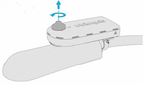
8.1 Remove the open cap by twisting counterclockwise and pull out.
8.2 Insert the photocell into the NEMA connector on the top of the UbiHub and twist clockwise until locked in place.

CAUTION: The UbiHub does not need a photocell to function, but should always have something installed in the NEMA. Never leave the top NEMA socket open.
8.3 Installation of the UbiHub is now complete. Make sure UbiHub and all elements are connected and secured firmly in place.

CAUTION: Double check the mounting bracket is snug and secure and ensure the blue films have been removed from the camera lenses and top light sensor.
Support and Technical Specifications:

FCC statement
This device complies with Part 15 of the FCC Rules. Operation is subject to the following two conditions:
- This device may not cause harmful interference, and
- This device must accept any interference received, including interference that may cause undesired operation.
Changes or modifications not expressly approved by Ubicquia, Inc. could void the user’s authority to operate the equipment.
NOTE: This equipment has been tested and found to comply with the limits for a Class B digital device, pursuant to part 15 of the FCC Rules. These limits are designed to provide reasonable protection against harmful interference in a residential installation. This equipment generates, uses and can radiate radio frequency energy and , if not installed and used in accordance with the instructions, may cause harmful interference to radio communications. However, there is no guarantee that interference will not occur in a particular installation. If this equipment does cause harmful interference to radio or television reception, which can be determined by turning the equipment off and on, the user is encouraged to try to correct the interference by one or more of the following measures:
- Reorient or relocate the receiving antenna.
- Increase the separation between the equipment and receiver.
- Connect the equipment into an outlet on a circuit different from that to which the receiver is connected.
- Consult the dealer or an experienced radio/TV technician for help.
RF

Safety Statements and Warnings 
This product has been ETL listed and complies with U.S. product safety standards.
![]() WARNING statements describe conditions that may lead to personnel injury including potentially fatal injuries if the device is not properly installed and warnings are not properly followed.
WARNING statements describe conditions that may lead to personnel injury including potentially fatal injuries if the device is not properly installed and warnings are not properly followed.
![]() CAUTION statements describe conditions that may lead to equipment damage.
CAUTION statements describe conditions that may lead to equipment damage.
- Electrical shock can cause serious or fatal injury. Only qualified personnel should install, maintain or troubleshoot this equipment.
- Installation must be carried out strictly according to the steps in this manual, including use of relevant tools and equipment as required. For example: safety gloves, device tether, warning labels, flash lamp, helmet, and/or work clothes, etc.
- In the process of installation, please ensure the weather is suitable for outdoor high power electrical work. If possible, the installer should avoid installing in the rain, or allowing the NEMA to get wet.
![]() WARNING
WARNING
- The product is required to be installed and to be connected to mains power by a skilled or qualified personnel in accordance with local and national codes or regulations.
- Suitably rated approved circuit breaker is to be attached during end installation as per applicable local and national codes or regulations.
- Suitable lightning arrester is intended to be installed during end installation as per applicable local and national codes or regulations.
![]() WARNING
WARNING
RF Exposure Compliance – to meet FCC and ISED limits for RF exposure, this device must be installed to provide a separation distance greater than 40 cm from all persons during normal operation.
![]()
Documents / Resources
 |
ubicquia APAI Ubihub Simply Connected Simply Smart [pdf] Installation Guide UBH01, 2AECKUBH01, APAI, AP6, Ubihub Simply Connected Simply Smart |


