![]() Material Nr.
Material Nr.
341-10006
 Linear Encoder
magnetostrictive
Assembly Instructions
 Copyright protection
This Manual, including the illustrations contained therein, is subject to copyright protection. Use of this Manual by third parties in contravention of copyright regulations is not permitted. Reproduction, translation as well as electronic and photographic archiving and modification require the written content of the manufacturer. Violations shall be subject to claims for damages.
Subject to modifications
The right to make any changes in the interest of technical progress is reserved.
Document information
Release date / Rev. date: 05/12/2025
Document / Rev. no.: TR-ELA-BA-DGB-0004 v18
File name: TR-ELA-BA-DGB-0004 v18.docx
Author: MÜJ
Font styles
Italic or bold font styles are used for the title of a document or are used for highlighting.
Courier font displays text, which is visible on the display or screen and software menu selections.
” < > ” indicates keys on your computer keyboard (such as <RETURN>).
Revision index
| Revision | Date | Index |
| First release | 06/19/2007 | 00 |
| Additions in the technical data | 01/15/2008 | 01 |
| Modification of the standards | 07/20/2009 | 02 |
| Modification of the warnings | 08/05/2011 | 03 |
| Actualization | 03/09/2015 | 04 |
| Intended use edited | 07/14/2015 | 05 |
| Tolerance notes LP-system | 06/20/2016 | 06 |
| – Mechanical characteristics removed -> reference to the product data sheets – Other applicable documents |
08/25/2016 | 07 |
| LMRI, LMPI and LMRB added | 01/18/2017 | 08 |
| Chapter “Installation in hydraulic cylinders” added | 05/18/2017 | 09 |
| LMRS and LMPS added | 03/12/2018 | 10 |
| LMRB-27 warning added (chapter 2.9) | 03/16/2018 | 11 |
| Upgrading of the LMRB-27 warning notice (chapter 2.9) | 06/06/2018 | 12 |
| LMR-70 and notes for multiple redundant measuring systems added | 07/15/2019 | 13 |
| Chapter “Mechanics profile- housing design”, Magnet distance: Universal image inserted | 03/18/2020 | 14 |
| Instructions for mounting, rod housing design | 11/30/2020 | 15 |
| Magnet T2-S5520 replaced with T2-S5520N | 03/17/2021 | 16 |
| Drawing corrected “Installation example LA-66”: Pos. C and D swapped | 10/18/2024 | 17 |
| Distance correction for magnet T2-S5520N: 10 -5 mm | 05/12/2025 | 18 |
General information
This Assembly Instruction includes the following topics:
- General functional description
- Basic safety instructions with declaration of the intended use
- Instructions for mounting
- Installation in hydraulic cylinders
As the documentation is arranged in a modular structure, this Assembly Instructions are supplementary to other documentation, such as product datasheets, dimensional drawings, leaflets and interface-specific User Manuals etc.
1.1 Applicability
These Assembly Instructions apply exclusively to the following measuring system models:
- LA / LP
- LMR / LMP
- LMRI / LMPI
- LMRS / LMPS
- LMRB
The products are labeled with affixed nameplates and are components of a system.
1.2 Other applicable documents
- the operator’s operating instructions specific to the system
- these Assembly Instructions
- interface-specific User Manual
- Pin assignment
- Dimension drawing
- Product data sheet: www.tr-electronic.com/s/S013471
1.3 EU Declaration of conformity
The measuring systems have been developed, designed and manufactured under observation of the applicable international and European standards and directives.
A corresponding declaration of conformity can be requested from TR-Electronic GmbH.
The manufacturer of the product, TR-Electronic GmbH in D-78647 Trossingen, operates a certified quality assurance system in accordance with ISO 9001.
1.4 Abbreviations and definitions
| LA / LMR | Linear-Absolute Measuring System, type with tube-housing |
| LMRB | Linear-Absolute Measuring System, type with tube-housing (Basic version) |
| LMRI | Linear-Absolute Measuring System, type with tube-housing (Industrial standard) |
| LMRS | Linear-Absolute Measuring System, type with tube-housing and decentralized interface unit (Standard version) |
| LP | Linear-Absolute Measuring System, type with profile-housing |
| LMP | Linear-Absolute Measuring System, type with profile-housing |
| LMPI | Linear-Absolute Measuring System, type with profile-housing (Industrial standard) |
| LMPS | Linear-Absolute Measuring System, type with profile-housing (Standard version) |
| EC | European Community |
| EU | European Union |
| EMC | Electro Magnetic Compatibility |
| ESD | Electro Static Discharge |
| IEC | International Electrotechnical Commission |
| NEC | National Electrical Code |
| VDE | Association for Electrical, Electronic & Information Technologies |
1.5 General functional description
The measuring principle is based on a run time measurement in the ultrasound area.
The ultrasound propagation time is path proportional and is evaluated in an electronics. A ferromagnetic wire is (magnetostrictive measuring element shaft conductor) in a reed capsule tense, this one are pressurized with a current pulse. A radial magnetic field arises from the current pulse therefore.
The position sensor (Permanent magnet) is a non-contact and wear free measurement magnetic system, which produces a magnetic axial field, related to the wire. If the two magnetic fields, radially from the wire and axial from the magnet, meet one another at the measuring point, then a torsion impulse will generated.
This torsion impulse moves as acoustic wave of the measuring body with constant ultrasonic sound speed of the measuring point in both directions of the wire.
Over a sensing element in the sensor head the ultrasonic sound signal is recorded and converted into electrical away-proportional output signal. The acoustic wave of the measuring body moving in both directions are weakened in the damping zones at the beginning and end of the measuring element.
The time difference of sending the current pulse up to the arrival of the torsion impulse converts measuring electronics into an away-proportional output signal and makes this available as digital or analog signal.
Measuring principle, standard measuring system:

- Current impulse
- Slide wire
- Damping zone
- Position sensor (Magnet)
- Magnetic field, produced by a current impulse
- Resulting magnetic field at the position sensor
- Answer signal of the torsion impulse
- Measuring sensor Receipt coil
Basic safety instructions
2.1 Definition of symbols and instructions
![]() WARNING
WARNING
means that death or serious injury can occur if the required precautions are not met.
![]() CAUTION
CAUTION
means that minor injuries can occur if the required precautions are not met.
NOTICE
means that damage to property can occur if the required precautions are not met.
![]() indicates important information or features and application tips for the product used.
indicates important information or features and application tips for the product used.
![]() means that appropriate ESD-protective measures are to be considered according to DIN EN 61340-5-1 supplementary sheet 1.
means that appropriate ESD-protective measures are to be considered according to DIN EN 61340-5-1 supplementary sheet 1.
2.2 Obligation of the operator before start-up
As an electronic device the measuring system is subject to the regulations of the EMC Directive.
It is therefore only permitted to start up the measuring system if it has been established that the system/machine into which the measuring system is to be fitted satisfies the provisions of the EU EMC Directive, the harmonized standards, European standards or the corresponding national standards.
2.3 General risks when using the product
The product, hereinafter referred to as “the measuring system”, is manufactured according to state-of-the-art technology and accepted safety rules. Nevertheless, non-intended use can pose a danger to life and limb of the user or third parties, or lead to impairment of the measuring system or other property! Only use the measuring system in a technically faultless state, and only for its intended use, taking safety and hazard aspects into consideration, and observing the
Other applicable documents! Faults which could threaten safety should be eliminated without delay!
2.4 Intended use
The measuring system is used to measure linear movements and to condition the measurement data for the subsequent control of industrial control processes.
Intended use also includes:
- observing all instructions in the other applicable documents,
- observing the nameplate and any prohibition or instruction symbols on the measuring system,
- observing the enclosed documents,
- operating the measuring system within the limit values specified in the technical data, see Product Data Sheet.
2.5 Non-intended use
Danger of death, physical injury and damage to property in case of nonintended use of the measuring system!
![]() WARNING
WARNING
![]() As the measuring system does not constitute a safety component according to the EC machinery directive, a plausibility check of the measuring system values must be performed through the subsequent control system.
As the measuring system does not constitute a safety component according to the EC machinery directive, a plausibility check of the measuring system values must be performed through the subsequent control system.
![]() It is mandatory for the operator to integrate the measuring system into his own safety concept.
It is mandatory for the operator to integrate the measuring system into his own safety concept.
NOTICE
![]() The following area of use is especially forbidden:
The following area of use is especially forbidden:
– In environments where there is an explosive atmosphere
– for medical purposes
2.6 Warranty and liability
The General Terms and Conditions (“Allgemeine Geschäftsbedingungen”) of TR-Electronic GmbH always apply. These are available to the operator with the Order Confirmation or when the contract is concluded at the latest. Warranty and liability claims in the case of personal injury or damage to property are excluded if they result from one or more of the following causes:
- Non-intended use of the measuring system.
- Improper assembly, installation, start-up and programming of the measuring system.
- Incorrectly undertaken work on the measuring system by unqualified personnel.
- Operation of the measuring system with technical defects.
- Mechanical or electrical modifications to the measuring systems undertaken autonomously.
- Repairs carried out autonomously.
- Third party interference and Acts of God.
2.7 Organizational measures
- The other applicable documents must always be kept accessible at the place of use of the measuring system.
- In addition to the other applicable documents, generally applicable legal and other binding accident prevention and environmental protection regulations are to be observed and must be mediated.
- The respective applicable national, local and system-specific provisions and requirements must be observed and mediated.
- The operator is obliged to inform personnel on special operating features and requirements.
- The personnel instructed to work with the measuring system must have read and understood the Assembly Instruction, especially the chapter “Basic safety instructions” prior to commencing work.
- The nameplate and any prohibition or instruction symbols applied on the measuring system must always be maintained in a legible state.
- Do not undertake any mechanical or electrical modifications on the measuring system, apart from those explicitly described in the other applicable documents.
- Repairs may only be undertaken by the manufacturer or a facility or person authorized by the manufacturer.
2.8 Personnel qualification; obligations
- All work on the measuring system must only be carried out by qualified personnel. Qualified personnel includes persons, who, through their training, experience and instruction, as well as their knowledge of the relevant standards, provisions, accident prevention regulations and operating conditions, have been authorized by the persons responsible for the system to carry out the required work and are able to recognize and avoid potential hazards.
- The definition of “Qualified Personnel” also includes an understanding of the standards VDE 0105-100 and IEC 364 (source: e.g. Beuth Verlag GmbH, VDEVerlag GmbH).
- Define clear rules of responsibilities for the assembly, installation, start-up and operation. The obligation exists to provide supervision for trainee personnel !
2.9 Safety informations
- Destruction, damage or malfunctions of the measuring system and risk of physical injury!
 De-energize the system before carrying out wiring work or opening and closing electrical connections.
 WARNING
Do not carry out welding if the measuring system has already been wired up or is switched on.
NOTICE
Series LMRB-27: Position jumps, faulty position output!
– Only interface units and sensors with the same order number and the same serial number according to the name plate may be connected together.
Ensure that the area around the assembly site is protected from corrosive media (acid, etc.).
NOTICE
Avoid any shocks (e.g. hammer-blow) on the measuring system while mounting.
Do not bend the sensor rod.
Do not install the measuring system next to magnetic fields.
Do not open the measuring system.  The measuring system contains electrostatically endangered circuit elements and units which can be destroyed by an improper use.
Contacts of the measuring system connection contacts with the fingers are to be avoided, or the appropriate ESD protective measures are to be applied. Disposal
If disposal has to be undertaken after the life span of the device, the respective applicable country-specific regulations are to be observed.
Transportation / Storage
Notes on transportation
Do not drop the device or expose it to strong strokes!
Device contains a magnetoresistive sensor.
Only use the original packaging!
The wrong packaging material can cause damage to the device during transportation.
Storage
Storage temperature: see product data sheet Store in a dry place
Instructions for mounting / schematic
Before mounting TR-linear-Transducer, make sure there are no strong magnetic and electric interference fields in the vicinity.
Inadmissible interference fields can influence the measuring precision. The field strength may be max. 3 mT in the vicinity of the measuring rod.
4.1 Mechanics rod housing design
The measurement is one coupled contactlessly about the magnetic field of the position sensor on the sensor rod. The precision of the measurements is among others addicted to the balance of magnetic field geometry. This means for the mechanics, that the position sensor has to be led centrically add-only and axially parallel to the rod precisely.
4.2 Mechanics profile- housing design
Since the position sensor by the measuring body mechanically one leads, is relatively simple the installation the TR-linear-Transducer system. The exact guidance of the captive-sliding magnet and non-contact and wear free measurement system each other optimally. In order to reduce the wear between captive-sliding magnet and measuring body to a minimum, the dimensional tolerances for angle and parallel disalignment must be absolutely kept:

The exact of the measured value depends also on the symmetry of magnetic field geometry. If no captive-sliding magnet is used, the position sensor must be led exactly in axial direction to the measuring body. The admissible maximum distance between position sensor and measuring body may not be exceeded:
Distinction:
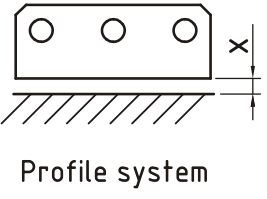 |
LP-Systems | ||
| Magnet: | Art.-No.: | Magnet distance: | |
| T4U3820 | 49-155-003 | X = 3.2 -2.4 mm | |
| LMP-Systems | |||
| Magnet: | Art.-No.: | Magnet distance: | |
| T1-S5520 | 49-155-009 | X = 3 -2 mm | |
| T2-S5520N | 49-155-032 | X = 10 -5 mm | |
| T1-S3818 | 49-155-015 | X = 3 -2 mm | |
The mounting material for the position sensor should absolutely consist of not magnetizable material.
If magnetizable mounting material is used, a spacer from not magnetizable material with 10 mm thickness and min. 3 mm must be planned more largely in the distance to the extent of the position sensor. The spacer is to be installed between the position sensor and its attachment. The screws must be from not magnetizable material.

4.3 Assembly diagram of the rod housing design

A: The linear transducer is fixed directly with the thread or a nut/mother with the mounting plate, with one attraction moment of < 50 Nm. The mounting material for the way sensor and position sensor B should absolutely consist of not magnetizable material.
C: If magnetizable mounting material is used, a spacer from not magnetizable material with 10 mm thickness and min. 3 mm must be planned more largely in the distance to the extent of the position sensor. The spacer is to be installed between the position sensor and its attachment. The screws must be from not magnetizable material.
D: The hydraulic sealing at the flange contact surface is recommended by means of O-ring in a cylinder soil groove. It can take place the sealing also with an O-ring in the thread runout groove.

E: Horizontal inserted rods > 1.5 m long should be supported and a position sensor open to the extent be used.
F: Optionally the linear transducer can be supplied at the tubing point with a blind hole thread M4x5. This can be used for the rod end bearing.
![]() The maximum values for Vibration and Shock specified in the product data sheets are only achieved if the measuring system is firmly mounted or damped on both sides. Not “freely vibrating”.
The maximum values for Vibration and Shock specified in the product data sheets are only achieved if the measuring system is firmly mounted or damped on both sides. Not “freely vibrating”.
Installation in hydraulic cylinders
This chapter applies exclusively to the following measuring systems series that made for the mounting with hydraulic cylinders:
| Series | Sealing | Mounting |
| LA-41 | Radial sealing | for external mounting to a hydraulic cylinder |
| LA-42 | Axial sealing | for external mounting to a hydraulic cylinder |
| LA-46 | Radial sealing | for external mounting to a hydraulic cylinder (exchangeable sensor) |
| LMRI-46 | Radial sealing | for external mounting to a hydraulic cylinder (exchangeable sensor) |
| LMR-48 | Radial sealing (at the housing) | for mounting into a hydraulic cylinder (applicable for mobile machines) |
| LA-65 | Axial sealing | for external mounting to a hydraulic cylinder (exchangeable sensor) |
| LA-66 | Axial sealing | for external mounting to a hydraulic cylinder |
| LMR-70 | Radial sealing | for external mounting to a hydraulic cylinder |
At the installation of the measuring system into the hydraulic cylinders the device specific data and specifications must be taken into account.
5.1 Sealing options
5.1.1 Axial sealing

5.1.2 Radial sealing

5.2 Installation types with magnetizable material
If at the installation of the linear sensor magnetizable materials are used, it is necessary to use not magnetizable material for the spacer with minimum 10 mm thickness and minimum 3 mm bigger than the perimeter of the position sensor. The spacer must be mounted between the position sensor and its mounting. For mounting the position sensor, screws must be used of not magnetizable materials such as brass, aluminum, plastic etc..
The TR-Linear-Sensors which are made for the external mounting into the hydraulic cylinder are screwed over a M18 x 1.5 thread. On the side of the flange the sealing is made radially or axially via an O-ring (No scope of supply!).
5.2.1 Mounting example LA-66

| A | Hydraulic cylinder |
| B | Piston rod |
| C | Spacer, consisting of not magnetizable material |
| D | Magnet (Position sensor) |
| E | Measuring system |
| F | Connector plug |
5.2.2 Mounting example LMR-48, version with M12-male connector
The LMR-48 linear sensor is fit into the hydraulic cylinder and secured from twisting with a grub screw (DIN 913 M5). The sealing is realized by means of an O ring at the device housing.

| A | Hydraulic cylinder |
| B | Piston rod |
| C | Spacer, consisting of not magnetizable material |
| D | Magnet (Position sensor) |
| E | Measuring system |
| F | Plug with plug holder |
| G | O ring |
5.2.2.1 Plug mounting
The plug is already pre-assembled and must be plugged through the drilling of the hydraulic cylinder in to the plug holder. The plug holder with the connected plug must be mounted now with four M4 cylinder head screws to the hydraulic cylinder.

5.3 Unusual features
At the linear sensors of the series LA-65-H and LA-46-H the pressure tube and the sensor element are mechanically independent.
Therefore the pressure tube remains at the sensor exchange in the hydraulic cylinder.
Furthermore the hydraulics system remains under pressure and long emptying times or filling times are therefore dropped.
Example LA-65-H

Example LA-46-H

5.4 Required torque
5.4.1 Calculation example axial sealing
Sensor type with thread M18x1.5, axial sealing via O-ring 23.47 x 2.62 (No scope of supply!)
LA-42 / LA-65-H / LA-66
A) Required locking force, dependent on the pressure on the flange
| 15 | p = | 600,0 bar | static hydraulic pressure at the sensor flange |
| 16 | d_Oring = | 23,5 mm | O-ring-Æ, mounting surface |
| 17 | F_Kl = | 25 957,8 N | required locking force (related to hydraulic pressure) |
B) Required mounting prestressing force, dependent on mounting case
| 18 | ka = | 1,6 [-] | Attraction factor for tightening with torque wrench (I) |
| 19 | kl = | 1,2 [-] | Loosening factor for static load (II) |
| 20 | F_VM = | 49 838,9 N | Mounting-prestressing force, related to ka and kl |
C) Thread geometry and thread friction
| 21 | D = | 18,0 | mm | Nominal thread diameter |
| 22 | P = | 1,5 | [-] | Thread lead |
| 23 | D2 = | 17,03 | mm | Pitch diameter |
| 24 | phi = | 0,028 | rad | Thread angle |
| 25 | my_k = | 0,12 | [-] | Friction coefficient for thread friction 1″leicht geölt” (III) |
| 26 | phi_G= | 0,119 | rad | Angle of friction, see my_k (11) |
| 27 | ra = | 11,7 | mm | Friction radius, see O-ring-Æ (2) |
D) Required torque for p = 600 bar
28 MA = 133 Nm Calculated torque (IV)
(I) see “Maschinenelemente” (Machine elements), Roloff/Matek, table A8-11
(II) see “Maschinenelemente” (Machine elements), Roloff/Matek, table A8-9
(III) see “Maschinenelemente” (Machine elements), Roloff/Matek, table A8-12a
(IV) see “Maschinenelemente” (Machine elements), Roloff/Matek, equation 8.20
5.4.2 Calculation example radial sealing
Sensor type with thread M18x1.5, radial sealing via O-ring 15.4 x 2.1 (No scope of supply!)
LA-41 / LA-46 / LMRI-46 / LMR-70
A) Required locking force, dependent on the pressure on the flange
| 1 | p = | 600,0 bar | static hydraulic pressure at the sensor flange |
| 2 | d_Oring = | 15,4 mm | O-ring-Æ, mounting surface |
| 3 | F_Kl = | 11 175,9 N | required locking force (related to hydraulic pressure) |
B) Required mounting prestressing force, dependent on mounting case
| 4 | ka = | 1,6 [-] | Attraction factor for tightening with torque wrench (I) |
| 5 | kl = | 1,2 [-] | Loosening factor for static load (II) |
| 6 | F_VM = | 21 457,7 N | Mounting-prestressing force, related to ka and kl |
C) Thread geometry and thread friction
| 7 | D = | 18,0 | mm | Nominal thread diameter |
| 8 | P = | 1,5 | [-] | Thread lead |
| 9 | D2 = | 17,03 | mm | Pitch diameter |
| 10 | phi = | 0,028 | rad | Thread angle |
| 11 | my_k = | 0,12 | [-] | Friction coefficient for thread friction 2″leicht geölt” (III) |
| 12 | phi_G= | 0,119 | rad | Angle of friction, see my_k (11) |
| 13 | ra = | 7,7 | mm | Friction radius, see O-ring-Æ (2) |
D) Required torque for p = 600 bar
14 MA = 47 Nm Calculated torque (IV)
(I) see “Maschinenelemente” (Machine elements), Roloff/Matek, table A8-11
(II) see “Maschinenelemente” (Machine elements), Roloff/Matek, table A8-9
(III) see “Maschinenelemente” (Machine elements), Roloff/Matek, table A8-12a
(IV) see “Maschinenelemente” (Machine elements), Roloff/Matek, equation 8.20
Accessories
www.tr-electronic.com/products/linear-encoders/accessories.html
EU Declaration of Conformity
The linear measuring systems listed in the attached list of validity have been developed, designed and manufactured in accordance with the following EU directives:
| Electromagnetic Compatibility (EMC) | 2014/30/EU (L 96/79) |
| Restriction of the use of certain hazardous substances in electrical and electronic equipment (RoHS) | 2011/65/EU (L 174/88) |
under the sole responsibility of:
TR-Electronic GmbH
Eglishalde 6
D – 78647 Trossingen
Tel.: 07425/228-0
Fax: 07425/228-33
Deutschland / Germany
The following harmonized standards were applied:
| Generic standards – Electromagnetic compatibility, Immunity (Industrial environments) |
EN 61000-6-2:2005/AC:2005 |
| Generic standards – Electromagnetic compatibility, Emissions (Commercial environments) |
EN 61000-6-3:2007/A1:2011 |
| Technical documentation for the assessment of electrical and electronic products with respect to the restriction of hazardous substances |
EN IEC 63000:2018 |
Trossingen, 02/10/2023

List of validity
Series: LMRB 27
Order No.: 341-xxxxx, 343-xxxxx
Type: LMRB-27
Series: LMP 30
Order No.: 322-xxxxx
Type: LMP-30
Series: LMRS 34
Order No.: 344-xxxxx
Type: LMRS-34
Series: LMPS 34
Order No.: 345-xxxxx
Type: LMPS-34
Series: LP 38
Order No.: 307-xxxxx
Type: LP-38
Series: LA 41
Order No.: 304-xxxxx, 305-xxxxx, 306-xxxxx, 309-xxxxx
Type: LA-41, LA-41A, LA-41K, LA-41KA
Series: LA 42
Order No.: 311-xxxxx
Type: LA-42, LA-42K
Series: LA 46
Order No.: 321-xxxxx
Type: LA-46, LA-46K, LA-46H, LA-46KH, LA-46/42, LA-46/42K
Series: LP 46
Order No.: 320-xxxxx
Type: LP-46, LP-46K
Series: LMRI 46
Order No.: 339-xxxxx
Type: LMRI-46
Series: LMPI 46
Order No.: 340-xxxxx
Type: LMPI-46
Series: LA 47
Order No.: 328-xxxxx, 338-xxxxx
Type: LA-47
Series: LMR 48
Order No.: 327-xxxxx
Type: LMR-48
Series: LMP 48
Order No.: 333-xxxxx
Type: LMP-48
Series: LA 50
Order No.: 325-xxxxx
Type: LA-50
Series: LMC 55
Order No.: 326E-xxxxx, 326M-xxxxx, 326S-xxxxx
Type: LMC-55
Series: LA 66
Order No.: 312-xxxxx
Type: LA-66, LA-66K
Series: LMR 70
Order No.: 335-xxxxx
Type: LMR-70
Series: LA 80
Order No.: 314-xxxxx
Type: LA-80
Series: LAK01
Order No.: 315-xxxxx
Type: LAK01
UK Declaration of Conformity
The linear measuring systems listed in the attached list of validity have been developed, designed and manufactured in accordance with the UK statutory instruments and their amendments:
| The Electromagnetic Compatibility Regulations 2016 | S.I. 2016 No. 1091 |
| The Restriction of the Use of Certain Hazardous Substances in Electrical and Electronic Equipment Regulations 2012 | S.I. 2012 No. 3032 |
under the sole responsibility of the manufacturer:
TR-Electronic GmbH
Eglishalde 6
D – 78647 Trossingen
Tel.: +49 7425/228-0
Fax: +49 7425/228-33
Germany
Name and address of authorised representative:
TR-Electronic Ltd.
4 William House
Old St. Michaels Drive
GB – Braintree Essex CM7 2AA
Tel.: +44 1 371 876 187
Fax: +44 1 371 876 287
The following designated standards were applied:
| Generic standards – Electromagnetic compatibility, Immunity (Industrial environments) |
EN 61000-6-2:2005/AC:2005 |
| Generic standards – Electromagnetic compatibility, Emissions (Commercial environments) |
EN 61000-6-3:2007/A1:2011 |
| Technical documentation for the assessment of electrical and electronic products with respect to the restriction of hazardous substances |
EN IEC 63000:2018 |
Trossingen, 02/10/2023
List of validity
| Series: LMRB 27 | Order No.: 341-xxxxx, 343-xxxxx Type: LMRB-27 |
| Series: LMP 30 | Order No.: 322-xxxxx Type: LMP-30 |
| Series: LMRS 34 | Order No.: 344-xxxxx Type: LMRS-34 |
| Series: LMPS 34 | Order No.: 345-xxxxx Type: LMPS-34 |
| Series: LP 38 | Order No.: 307-xxxxx Type: LP-38 |
| Series: LA 41 | Order No.: 304-xxxxx, 305-xxxxx, 306-xxxxx, 309-xxxxx Type: LA-41, LA-41A, LA-41K, LA-41KA |
| Series: LA 42 | Order No.: 311-xxxxx Type: LA-42, LA-42K |
| Series: LA 46 | Order No.: 321-xxxxx Type: LA-46, LA-46K, LA-46H, LA-46KH, LA-46/42, LA-46/42K |
| Series: LP 46 | Order No.: 320-xxxxx Type: LP-46, LP-46K |
| Series: LMRI 46 | Order No.: 339-xxxxx Type: LMRI-46 |
| Series: LMPI 46 | Order No.: 340-xxxxx Type: LMPI-46 |
| Series: LA 47 | Order No.: 328-xxxxx, 338-xxxxx Type: LA-47 |
Series: LMR 48
Order No.: 327-xxxxx
Type: LMR-48
| Series: LMP 48 | Order No.: 333-xxxxx Type: LMP-48 |
| Series: LA 50 | Order No.: 325-xxxxx Type: LA-50 |
| Series: LMC 55 | Order No.: 326E-xxxxx, 326M-xxxxx, 326S-xxxxx Type: LMC-55 |
| Series: LA 66 | Order No.: 312-xxxxx Type: LA-66, LA-66K |
| Series: LMR 70 | Order No.: 335-xxxxx Type: LMR-70 |
| Series: LA 80 | Order No.: 314-xxxxx Type: LA-80 |
| Series: LAK01 | Order No.: 315-xxxxx Type: LAK01 |
LMRS_27*150


TR-Electronic GmbH
D-78647 Trossingen
Eglishalde 6
Tel.: (0049) 07425/228-0
Fax: (0049) 07425/228-33
E-mail: info@tr-electronic.de
www.tr-electronic.de
Documents / Resources
 |
TR electronic TR-ELA Absolute Linear Encoder [pdf] Instruction Manual TR-ELA-BA-DGB-0004 v18, TR-ELA-KE-DGB-0079-02, TR-ELA-KE-GB-0080-02, TR-ELA Absolute Linear Encoder, TR-ELA, Absolute Linear Encoder, Linear Encoder, Encoder |