TERACOM TST320 2 Channel Thermocouple Module With Modbus RTU Interface
Short description
TST320 is a versatile and reliable solution for temperature monitoring and control, supporting two thermocouples.
With its MODBUS RTU interface, it seamlessly integrates into industrial systems, enabling easy communication and data exchange with other devices. It offers precise temperature readings for various applications and industries, ensuring accurate process control and optimization. Its compact design and user-friendly interface make it a practical choice for industrial automation and monitoring needs.
Features
- 24-bit ADC with DSP processing
- RS-485 interface supporting up to 63 nodes
- LED indicator displaying communication status
- Compatibility with all types of thermocouples
- Integrated 120-ohm termination resistor
- Firmware update capability via the interface
Applications
- Industrial temperature monitoring – Enables accurate temperature measurement in industrial processes, catering to diverse applications with various thermocouple types.
- HVAC system control – Integrates precise temperature regulation for efficient heating and cooling in residential, commercial, and industrial HVAC systems.
- Laboratory and research applications – Facilitates stable and accurate temperature monitoring in scientific experiments and research, including chemical reactions and material testing.
Specifications
- Physical characteristics
Dimensions: 35x86x59mm (2 module enclosure)
Weight: 75g
Mounting: On 35 mm DIN top-hat rail - Environmental limits
Operating temperature range: -20 to 60°C
Operating relative humidity range: 10 to 90% (non-condensing)
Storage temperature range: -25 to 65°C
Storage relative humidity range: 5 to 95% (non-condensing)
Ingress protection: IP40 (connections IP20) - Power supply
Operating voltage range (including -15/+20% according to IEC 62368-1): 5 to 30VDC
Current consumption: 15mA@12V - Thermocouples
Thermocouple types supported: J, K, T, N, E, B, R, and S
Temperature resolution: 0.01°
ADC conversation accuracy (max): ±0.1%
CJC accuracy (max): ±0.19%
Input conversion rate for both channels: 1 sample per second
With DSP (Digital Signal Processing) over 76865 samples for low-pass filtering and 50/60Hz notch filtering
Thermocouple break detection: Available - Interface
Protocol: Modbus RTU
Physical layer: RS-485 serial line
Number of bus transceivers: up to 63
Bus cable: Twisted, shielded, 2×0.5mm²
Response time ≤ 50ms
Master response time-out ≥ Response time + Answer time
The answer time depends on the number of bits and the baud rate.
Connectors
Type: 3.81mm pitch screwless pluggable for 28 to 16 (AWG) / 0.081 to 1.31 (mm²) wires - Isolation
Maximum working isolation voltage: 1500Vrms - Warranty
Warranty period: 3 years
Status indicator
The device status is indicated through a single LED positioned behind the semitransparent front panel:
- Steady blinking of the LED for 1 second indicates proper sensor functionality.
- A 3-second blink pattern signals a lack of communication with the controller.
- If the LED remains off, it indicates a lack of power supply to the device.
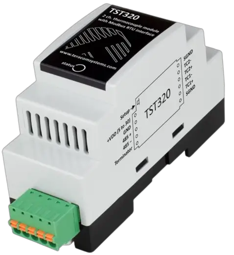
Pinout
- 5-pins connector
1 – +VDD (5 to 30)
2 – GND
3 – RS485+
4 – RS485-
5 – Terminator - 6-pins connector
1 – SGND (Shield)
2 – TC2-
3 – TC2+
4 – TC1-
5 – TC1+
6 – SGND (Shield)

Installation
Two-Wire MODBUS definition according to modbus.org:
“A MODBUS solution over a serial line should implement a “Two-Wire” electrical interface in accordance with EIA/TIA-485 standard. On such a “Two-Wire” topology, at any time one driver only has the right for transmitting.
In fact, a third conductor must also interconnect all the devices of the bus – the common.”

It is highly advisable to use a daisy-chain (linear) topology along with UTP/FTP cables when connecting multiple sensors. To ensure the interface functions correctly, terminators (120-ohm resistors) must be installed at both ends of the bus. The device comes equipped with a built-in 120-ohm resistor, and for bus termination, the terminals “485-” and “Term” should be shortened.

Factory default settings
To reset the device to its factory default settings, follow these steps:
- Disconnect the power supply.
- Press and hold the “Setup” button.
- While holding the button, reconnect the power supply.
- The status LED will remain ON for 3 seconds, then flash for 7 seconds, and finally turn ON again.
- Release the button. The device will restart with the factory default settings.
Firmware update
The device’s firmware can be updated either by a Teracom controller with MODBUS RTU support or through MBRTU-Update software.
To activate the sensor’s update mode, follow these steps:
- Disconnect the sensor from the bus and disconnect the power supply.
- Press and hold the “Setup” button.
- While holding the button, reconnect the power supply without releasing the button.
- The status LED will be ON for 3 seconds. If, within these 3 seconds, the button is released and pressed 3 times, the device will enter update mode.
- In update mode, the status LED will remain ON continuously.
Important: The sensor can only be updated when it is the only device on the bus.
Modbus address table
| Register name | R/W | FC | PDU decimal address | Logical decimal address | Data size | Default | Valid values |
| Holding registers | |||||||
| RS-485 address | R/W | 3,6,16 | 10 | 40011 | 16-bit uns. integer | 1 | 1 to 247 |
| Baud rate * | R/W | 3,6,16 | 11 | 40012 | 16-bit uns. integer | 19200 | 2400, 4800, 9600, 19200, 38400, 57600 |
| Parity, data, stop bits * | R/W | 3,6,16 | 12 | 40013 | 16-bit uns. integer | 1 | 1=E81, 2=O81, 3=N81 |
| Data order | R/W | 3,6,16 | 13 | 40014 | 16-bit uns. integer | 1 | 1=MSWF (MSW, LSW) a2=LSWF (LSW, MSW) |
| Device code | R | 3 | 14 | 40015 | 16-bit uns. integer | 0x0101 | |
| FW version | R | 3 | 15 | 40016 | 16-bit uns. integer | ||
| Vendor URL | R | 3 | 18 | 40019 | 64 bytes UTF-8 | teracomsystems.com | |
| Float test value (MSW) | R | 3 | 82 | 40083 | 32-bit float | 2 | -9.9(0xC11E6666) |
| Float test value (LSW) | R | 3 | 84 | 40085 | 32-bit float | 2 | -9.9(0xC11E6666) |
| Signed integer test value | R | 3 | 86 | 40087 | 16-bit sig. integer | 1 | -999(0xFC19) |
| Signed integer test value (MSW) | R | 3 | 87 | 40088 | 32-bit sig. integer | 2 | -99999(0xFFFE7961) |
| Signed integer test value (LSW) | R | 3 | 89 | 40090 | 32-bit sig. integer | 2 | -99999(0xFFFE7961) |
| Unsigned integer test value | R | 3 | 91 | 40092 | 16-bit uns. integer | 1 | 999(0x03E7) |
| Unsigned integer test value (MSW) | R | 3 | 92 | 40093 | 32-bit uns. integer | 2 | 99999(0x0001869F) |
| Unsigned integer test value (LSW) | R | 3 | 94 | 40853 | 32-bit uns. integer | 2 | 99999(0x0001869F) |
| TC1 temperature °C | R | 3 | 100 | 40101 | 32-bit float | 2 | |
| TC2 temperature °C | R | 3 | 102 | 40103 | 32-bit float | 2 | |
| TC1 min. temperature °C | R | 3 | 120 | 40121 | 32-bit float | 2 | |
| TC2 min. temperature °C | R | 3 | 122 | 40123 | 32-bit float | 2 | |
| TC1 max. temperature °C | R | 3 | 140 | 40141 | 32-bit float | 2 | |
| TC2 max. temperature °C | R | 3 | 142 | 40143 | 32-bit float | 2 | |
| TC1 temperature °F | R | 3 | 200 | 40201 | 32-bit float | 2 | |
| TC2 temperature °F | R | 3 | 202 | 40203 | 32-bit float | 2 | |
| TC1 min. temperature °F | R | 3 | 220 | 40221 | 32-bit float | 2 | |
| TC2 min. temperature °F | R | 3 | 222 | 40223 | 32-bit float | 2 | |
| TC1 max. temperature °F | R | 3 | 240 | 40241 | 32-bit float | 2 | |
| TC2 max. temperature °F | R | 3 | 242 | 40243 | 32-bit float | 2 | |
| TC1 temperature °C x 10 | R | 3 | 400 | 40401 | 16-bit sig. integer | 1 | |
| TC2 temperature °C x 10 | R | 3 | 401 | 40402 | 16-bit sig. integer | 1 | |
| TC1 min. temperature °C x 10 | R | 3 | 420 | 40421 | 16-bit sig. integer | 1 | |
| TC2 min. temperature °C x 10 | R | 3 | 421 | 40422 | 16-bit sig. integer | 1 | |
| TC1 max. temperature °C x 10 | R | 3 | 440 | 40441 | 16-bit sig. integer | 1 | |
| TC2 max. temperature °C x 10 | R | 3 | 441 | 40442 | 16-bit sig. integer | 1 | |
| TC1 temperature °F x 10 | R | 3 | 500 | 40501 | 16-bit sig. integer | 1 | |
| TC2 temperature °F x 10 | R | 3 | 501 | 40502 | 16-bit sig. integer | 1 | |
| TC1 min. temperature °F x 10 | R | 3 | 520 | 40521 | 16-bit sig. integer | 1 | |
| TC2 min. temperature °F x 10 | R | 3 | 521 | 40522 | 16-bit sig. integer | 1 | |
| TC1 max. temperature °F x 10 | R | 3 | 540 | 40541 | 16-bit sig. integer | 1 | |
| TC2 max. temperature °F x 10 | R | 3 | 541 | 40542 | 16-bit sig. integer | 1 | |
| TC1 temperature °C x 100 | R | 3 | 600 | 40601 | 16-bit sig. integer | 2 | |
| TC2 temperature °C x 100 | R | 3 | 602 | 40603 | 16-bit sig. integer | 2 | |
| TC1 min. temperature °C x 100 | R | 3 | 620 | 40621 | 32-bit sig. integer | 2 | |
| TC2 min. temperature °C x 100 | R | 3 | 622 | 40623 | 32-bit sig. integer | 2 | |
| TC1 max. temperature °C x 100 | R | 3 | 640 | 40641 | 32-bit sig. integer | 2 | |
| TC2 max. temperature °C x 100 | R | 3 | 642 | 40643 | 32-bit sig. integer | 2 | |
| TC1 temperature °F x 100 | R | 3 | 700 | 40701 | 32-bit sig. integer | 2 | |
| TC2 temperature °F x 100 | R | 3 | 702 | 40703 | 32-bit sig. integer | 2 | |
| TC1 min. temperature °F x 100 | R | 3 | 720 | 40721 | 32-bit sig. integer | 2 | |
| TC2 min. temperature °F x 100 | R | 3 | 722 | 40723 | 32-bit sig. integer | 2 | |
| TC1 max. temperature °F x 100 | R | 3 | 740 | 40741 | 32-bit sig. integer | 2 | |
| TC2 max. temperature °F x 100 | R | 3 | 742 | 40743 | 32-bit sig. integer | 2 | |
| Reset min and max values | R/W | 3,6 | 1000 | 41001 | 16-bit uns. integer | 1 | |
| TC1 type | R/W | 3,6 | 2100 | 42001 | 16-bit uns. integer | 1 | 0=J type,1=K type,2=T type, 3=N type, 4=E type, 5=B type, 6=R type, 7=S type |
| TC1 multiplier | R/W | 3,16 | 2101 | 42002 | 32-bit float | 2 | |
| TC1 offset | R/W | 3,16 | 2103 | 42004 | 32-bit float | 2 | |
| TC2 type | R/W | 3,6 | 2110 | 42011 | 16-bit uns. integer | 1 | 0=J type,1=K type,2=T type, 3=N type, 4=E type, 5=B type, 6=R type, 7=S type |
| TC2 multiplier | R/W | 3,16 | 2111 | 42012 | 32-bit float | 2 | |
| TC2 offset | R/W | 3,16 | 2113 | 42014 | 32-bit float | 2 | |
* The settings will take effect after restarting the device by power off, power on.
The shown logic decimal addresses are calculated with offsets 10001 (discrete inputs) and 40001 (holding registers).
MSW – Most significant word first – (bits 31 … 16), (bits 15 … 0);
LSW – Least significant word first – (bits 15 … 0), (bits 31 … 16);
PDU address – Actual address bytes used in a Modbus Protocol Data unit;
When TC is not available or in case of measurement error, for:
- a floating-point, the returned value is “NaN”;
- a 16-bit signed integer, the returned value is “-32768”(0x8000);
- a 32-bit signed integer, the returned value is “-2147483648”(0x80000000).
Recycling
![]() Recycle all applicable material.
Recycle all applicable material.
Do not dispose of in the regular household refuse.
CUSTOMER SUPPORT
www.teracomsystems.com
TST320-R1.2 – November 2023

Documents / Resources
 |
TERACOM TST320 2 Channel Thermocouple Module With Modbus RTU Interface [pdf] User Manual TST320 2 Channel Thermocouple Module With Modbus RTU Interface, TST320, 2 Channel Thermocouple Module With Modbus RTU Interface, Thermocouple Module With Modbus RTU Interface, Module With Modbus RTU Interface, Modbus RTU Interface, RTU Interface, Interface |