TAKSTAR AM Series Multi Function Analog Mixer

Important Safety Instructions

 This symbol, wherever used, alerts you to the presence of un-insulated and dangerous voltages within the product enclosure. These are voltages that may be sufficient to constitute the risk of electric shock or death.
 This symbol, wherever used, alerts you to important operating and maintenance instructions.
Please read.

WARNING
Describes precautions that should be observed to prevent the possibility of death or injury to the user.
CAUTION
Describes precautions that should be observed to prevent damage to the product.
Disposing of this product should not be placed in municipal waste but rather in a separate collection.

WARNING
Power Supply
Ensure that them a inssource voltage (AC outlet) matches the voltage rating of the product. Failure to do so could result in damage to the product and possibly the user. Unplug the product before electrical storms occur and when unused for long periods of time to reduce the risk of electric shock or fire.
External Connection
Always use proper ready-made insulated mains cabling (power cord). Failure to do so could result in shock/death or fire. If in doubt, seek advice from a registered electrician.
Do Not Remove Any Covers
Within the product are areas where high voltages may present. To reduce the risk of electric shock do not remove any covers unless the AC mains power cord is removed. Covers should be removed by qualified service personnel only.
No user serviceable parts inside.
Fuse
To prevent fire and damage to the product, use only the recommended fuse type as indicated in this manual. Do not short-circuit the fuse holder. Before replacing the fuse, make sure that the product is OFF and disconnected from the AC outlet.
Protective Ground
Before turning the unit ON, make sure that it is connected to Ground. This is to prevent the risk of electric shock.
Never cut internal or external Ground wires. Like wise, never remove Ground wiring from the Protective Ground Terminal.
Operating Conditions
Always install in accordance with the manufacturer’s instructions.
To avoid the risk of electric shock and damage, do not subject this product to any liquid/rain or moisture. Do not use this product when in close proximity to water.
Do not install this product near any direct heat source. Do not block areas of ventilation. Failure to do so could result in fire.
Keep product away from naked flames.
IMPORTANT SAFETY INSTRUCTIONS
- Read these instructions
- Follow all instructions
- Keep these instructions. Do not discard.
- Heed all warnings.
- Only use attachments / accessories specified by the manufacturer.
Power Cord and Plug
- Do not tamper with the power cord or plug. These are designed for your safety.
- Do not remove Ground connections!
- If the plug does not fit your AC out let seek advice from a qualified electrician.
- Protect the power cord and plug from any physical stress to avoid risk of electric shock.
- Do not place heavy objects on the power cord. This could cause electric shock or fire.
Cleaning
When required, either blow off dust from the product or use a dry cloth.
Do not use any solvents such as Benzol or Alcohol. For safety, keep product clean and free from dust.
Servicing
Refer all servicing to qualified service personnel only. Do not perform any servicing other than those instructions contained within the User’s Manual.
PORTABLE CART WARNING
Carts and stands – The component should be used only with a cart or stand that is recommended by the manufacturer.
A component and cart combination should be moved with care. Quick stops, excessive force, and uneven surfaces may cause the component and cart combination to overturn.
Introduction
- Thank you for purchasing this multi-function analog AM series mixer from TAKSTAR.
- It has 4 I 8 I 12 way ultra low noise preamplifier, 48V phantom power, 4 way stereo input, 1 way USB stand Body sound input; each channel with 3 balanced EQ, REC, SUB, Monitor, 24-byte digital effectors.
- There are 99 effect options.
- Please read the user instructions carefully before using your product.
Features
- 10 inputs,including 4 mies+ 3 Stereos(L+R)
- 14 inputs,including 8 mies+ 3 Stereos(L+R)
- 18 inputs,including 12 mies+ 3 Stereos(L+R)
- UR on main channel, SUB group, SOLO and other bus signal distribution buttons
- Built-in 99 kinds of 24BIT DSP +digital display
- 3 band EQ + 4ch independent compression
- Group output of SUB1/2
- Double 12 level monitoring
- PAN,MUTE, THO signal lamp
- 2 stereo aux return input+PC USB-A 2.0 interface+Bluetooth input, can be used for USB playback and other electronic equipment
- Aux + effect FX send ,REC recording output
- Independent monitoring + Headphones monitoring for output
- 60mm logarithmic fader
- 48V phantom power supply
Application
Suitable for all kinds of small & medium activities, conferences, multi-function hall, small performance
INSTALL SAMPLE
FRONT PANEL

Panel Function

- MIC/LINE/XLR
For connecting to a microphone, an instrument, or an audiodevice. These jacks support both XLR and phone plugs.
- INSERT
INSERT: These are unbalanced TRS (tip=send/out;,ring=return/in; sleeve=ground) phonetype bidirectional jacks. You can use these jacks to connect channels to devices such as graphic equalizers, compressors, and noise filters.
NOTE
Connection to an INSERT jack requires a special insertion cable as illustrated below.
- LINE 9/10 stereo input jacks
Unbalanced phone type line stereo input jacks - USB
This USB interface, a machine built-in MP3 player and recorder, support format: MP3, WAV, WMA flash memory capacity and format- USB flash operation has been proven to be compatible with up to 64GB flash.
(there is no guarantee that it will work with all types of USB flash memory.)Support for FAT16 and FAT32 formats - Avoid accidental deletion
Some USB flash devices have protection Settings to prevent data from being accidentally deleted. If your flash device contains important data, it is strongly recommended that you use write protection Settings to prevent data from being accidentally deleted.
- USB flash operation has been proven to be compatible with up to 64GB flash.
- LINE
For connecting to line-level devices such as an electric keyboard or an audio device. Use the [UMONO] jack on channel 2 for instruments, etc. with mono input. In this case, the sound input to the [UMONO] jack is output from both the L channel and R channel on the mixer. - REC
Rec output: Only TAPE channels use unbalanced RCA interface (TAPE INPUT) to connect stereo line signals, such as TAPE recorder, CD player, MP3 player, TV sound, etc. - SUB 1-2
These impedance-balanced 1/4″TRS jacks output the SUB 1-2 signals.Use these jacks to connect to the inputs of a multi-track recorder, external mixer, or similar device.
- CR OUT ( L._ R )
These are impedance-balanced1/4″TRS phone output jacks that you connect to your monitor system. These jacks output the signal before or after the faders for the various buses. The SOLO indicators in each section indicate which signal is being output.
NOTE
The SOLO switch has priority. To before monitor the post-fader signal, make sure to turn off all SOLO switches. - 9/1 0.AUX / EFX
You use these jacks, for example, to connect to an external effect device or a stage/studio monitoring system.
These are impedance-balanced* phone-type output jacks.- Impedance-balanced
Since the hot and cold terminals of impedance-balanced output jacks have the same impedance, these output jacks are less affected by induced noise.
- Impedance-balanced
- FX SW
Connect a foot switch to phone type input jack.An optional foot switch can be used to toggke the FX ON and OFF. - [PHONES
For connecting headphones.The socket supports stereo phone plug.If you need to connect headsets or earplugs with mini plugs, please use a switch device to connect. - MAIN OUT
Here are two main output interfaces: the convex XLR jacks provide balanced circuit information;The 1/4 “TRS jack provides a balanced or unbalanced signal.
Each xlr jack is parallel to its 1/4” trs jack, and the load phase Same signal.
This represents the last part of the entire mixing chain, connecting these jacks to you Main power on, active speaker, or a series of effect processors to make your mixing signal real The entity appears. - GAIN
Sets the volume of the microphone or line input signal provided to this channel.The GAIN knob is used to adjust the sensitivity of the microphone and the input signal of the circuit.This allows external signals to be adjusted to the desired internal control level. - COMP
Adjusts the amount of compression applied to the channel.As the knob is turned to the right the compression ratio increaes while the output gain is automatically adiusted accordingly. The result is smoother, more even dynamics because louder signals are attenuated while the overall levels boosted. The COMP indicator will light when the compressor operates.
NOTE
Avoid setting the compression too high, as the highter average output level that results may lead to feedback. - EQ
- High
Control the high frequency tone of each channel, Always set this control to the 12 o’clock position, but you can control the high frequency tone according to the speaker, the conditions of listening positionand listener’s taste, Clockwise rotation of the control increases level. - MID
This has a function which controls the middle frequency tone of each channel.Always set this control to the 12 o’clock position, but you can control the middle frequency tone all ording to the speaker, the conditions
of listening position and listener’s taste. Clockwise rotation of the control increase the level, and vice verse. - LOW
This has a function which controls the middle frequency tone of each channel.Always set this control to the 12 o’clock position, but you can control the middle frequency tone all ording to the speaker, the conditions
of listeningposition and listener’s taste. Clockwise rotation of the control increase the level, and vice verse.
- High
- EQ ON
This button is to let the signal entering the channel add EQ effect.
When the key up, the EQ function will not have an effect on the signal. When the key is pressed, the signal is controlled by EQ to produce the corresponding effect. In this way, you can compare the effect of EQ with that of no Eq. - AUX
The knob is used to control the size of the auxiliary sending signal of this channel, which is sent to the outside via the AUX SEND knob of the main control Equipment, such as effectors.
These controls have two functions:- The level used to control the effect, such as the reverberation effect of an external effect processing device loaded on the input signal.
- set up independent remixes of music in the studio or on the stage.(the output signal is after the push)


- FX
These knobs take advantage of each channel’s signal sent to the in-machine effect after processing and return to the stereo main channel.Channel fader, mute and other channel controls affect the effect output, but the sound phase adjustment does not (effect assist is after the push). - PAN
The pan control sends continuosly variable amounts of the post fader signal to either the left or right main busses. In the certer position equal amounts of signal are sent to the left and right busses. - MUTE
All output from the channel are enabled when the MUTE switch released and muted when the switch is down.- this switch is set to be on or off to listen to the channel pusher through the PHONES socket.
- close all unused channels to reduce noise.
- CHANNEL FADER
This is function to adjust the volume of signal connection into each channel and adjust the volume of output, together with master fader. Normal oper-ation is at the “O”mark, providing 4dB of gain above that point, if required. - MAIN and SUB1/2 Button
Press the switch (. )to output the channel signal to the corresponding SUB marshalling or MAIN bus.
- switch SUB 1-2: assign channel signals to sub1-2 marshalling (bus).
- MAIN switch: allocates channel signals to the MAIN Land R buses.
Note: to send signals to each bus, tum on the MUTE switch
- [SOLO]
Monitor button SOLO: the monitor before the putter attenuation.after pressing,LED light is lit, plug in with the headset The headphone jack of the mixer can hear the sound signal in front of the driver.  13/14 LEVEL
Used to adjust the level of the channel signal.
Note:To minimize noise, adjust the knobs on unused channels to a minimum.- REC LEVEL
Adjust the recording output signal level. - SUB / L, R Conversion
Use to switch the SUB / MAIN recording signals. - +48V LED and PHANTOM
When this switch is turned on (),the [+48V] LED lights and DC +48 V phantom power is supplied to the XLR plug on MIC/LINE input jack. Tum this switch on when using a phantompowered condenser microphone.
NOTICE
Be sure to leave this switch off ( ) if you do not need phantom power. Follow the important precautions below, in order to prevent noise and possible damage to external devices as well as the mixer if you turn thisswitch on ) .
- Be sure to leave this switch off ( ) when you connect a device that does not support phantom power to channel 1.
- Make sure to turn this switch off () when connecting/disconnecting a cable to/from channel 1.
3. Slide the fader on channel 1 to minimum before turning this switch on() /off () .
- Be sure to leave this switch off (
- POWER LED
The indicator on the mixer will light up when the POWER switch is turned on
WARNING:- Do not remove the ground pin of the plug.
- Use in strict accordance with the labeled voltage of the product.
- Rapidly turning the unit on and off in succession can cause it to malfunction. After turning the unit off, wait for at least 6 seconds before turning it on again.
- Note that the trace current continues to flow even while the switch is in the off position. If you do not plan to use the mixer for a while, be sure to unplug the power cord from the wall outlet.
- DISPLAY
- Function Display
- Display the running status or bluetooth connection status
- song time display
- song number display
- effect types(please refer to the list of effects on the right)
 DIGITAL EFFECTS
01-03 Ambience
04-06 Spring
07-16 Room
17-26 Plate
27-36 Hall
37-52 Echo
53-56 Pingpong
57-60 Slap Rev
61-68 Echo+rev
69-74 Chorus
75-80 Flanger
81-86 Delay+chorus
87-92 Rev+chorus
93-99 Ktv
- DIGITAL AUDIO

- FX PRESET
 Operational control instructions
A, MODE( touch button): short press: pre-selected mode, corresponding mode icon flicker display, followed by usb flash disk, Bluetooth, recording, sequential play, random play, single loop (short press DIGITAL AUDIO to confirm the switch).
B, MODE (touch the button lightly): Long press:- 1. In the recording mode, when the recording is stopped, you can enter the recording play.
- 2. In the non-recording mode, you can quickly the recording play.
C DIGITAL AUDIO (encoder keys) : Short Press - 1. Control operation or pause (including playing and recording).
- 2. When the mode icon flashes, confirm to switch to the current mode of flashing display.
- 3. Rotate the encoder to the pre-selected playlist to confirm playing the current corresponding song.
D, DIGITAL AUDIO (encoder keys) : Long press - 1. Control stop (including playing and recording).
- 2. When the recording has stopped, you can enter the recording file mode.
- 3. Disconnect the current Bluetooth connection in Bluetooth mode.
E, Encoder - 1. Pre-select the tracks to play when the usb flash disk is playing.
- 2. When bluetooth and recording files are played, switch previous song/ next song.
F, When the recording is played, the usb flash disk and recording icon are also displayed.
- [AUX MASTER] control knob +[SOLO] monitor button Controls the overall level of signals emitted from the AUX output.This auxiliary output is commonly used for power amplifiers to drive stage monitors so that the singer can hear himself on the amplified instrument, or for headphone amplifiers so that the singer is recording without the microphone receive the monitoring signal.
When SOLO monitoring button is pressed, the light will light up.You can hear the sound signal of the connected [AUX] interface device from the monitor, the monitor speaker and the monitor earphone. - [EFX] Knob +[SOLO] Monitoring Button
- Control the overall level of the signal emitted from the EFX output.This is usually used to control the volume of a signal connected to an external effector.
- When SOLO monitoring button is pressed, the light will light up.From the monitor, listening speaker, listening earphone to hear the external effects of the interface [EFX] sound signal.
- CONTROL ROOM/PHONE knob+ SUB/L, R Switch
- CONTROL ROOM/PHONE: Adjust the output signal to the monitor speaker/monitor earphone.
- SUB/L, R Switch: The input signal is sent to the listening speaker/listening headset by switching the key to select the main output or Headphones monitoring for output.
- METERS
The left and right level meters of the mixer are composed of two columns of 12 led lamps, led each has three colors to refer to Show the range of the level.
- EFX FADER
Using by this control, you can adjust signal level of echo repeat & exterior effect. - SUBFader
This fader controls the level of the marshalling signal, from “otr’ to “U” unified gain, and then to 1 O db The additional gain. - MAINFADER
These pushers control the level of the main mixer and affect the level meter and the main line level output. You can control what the audience hears and make sure there are no problems. If there is a problem, please adjust carefully to see if the level meter is overloaded and ensure that the output level is satisfactory to the audience.

Back panel function
Backside of Mixer
- 40.AC Jack
Standard iec power interface, if the power line provided by this mixer, can also use professional video recorder, musical instruments, computer three-hole iec wire connection. - 41 POWER Switch
Turns power to the unit on or off. Press the switch to the” I” position to turn on the power. Press the switch to the” O” position to turn off the power.
Note :
- Switching between starting and shutting down continuously and quickly will cause damage to the equipment. Do not try. The correct way should be to set the power to standby, please wait about 6 seconds before turning on again.
- Even if the switch is in standby (0) state, a small amount of current will enter the device.If you do not use the device for a period of time, be sure to pull out the DC power cord

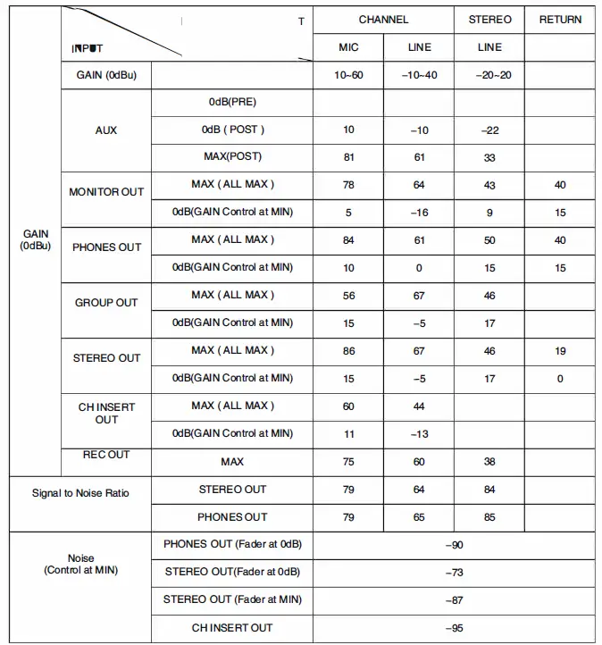
Specifications
0 dBu=0.775 Vrms, 0 dBV=1 Vrms
If you do not specify all the pushes will be set to the nominal position.(nominal position adjusted to 10 dB below maximum position}
Output impedance (Rs} of the signal generator =100 ohm, output load impedance =1 OOk ohm (TRS phone output)
The contents of this manual are the latest technical specifications at the time of printing.As the product will continue to improve, the specifications in this manual may not be in accordance with your product specifications.
Please go to the website to download the latest version of the manual. Technical specifications, equipment or accessories may vary from place to place, so please contact and confirm with local distributor.
Safety warnings
In order to avoid personal injury or property loss caused by electric shock, high temperature, fire, radiation, explosion, mechanical hazard and improper use, please read carefully and observe the following matters when using this product:
- When using the product, please confirm whether the connected device matches the power of the product and reasonably adjust the volume. Do not use the product for a long time in excess of the power and high volume of the product, so as to avoid abnormal product and hearing damage;
- Use if found abnormal (such as smoke, odor, etc.), please immediately turn off the power switch and unplug the power plug, and then send the product to dealers for maintenance;
- The product and accessories should be placed in a dry and ventilated place indoors, and should not be stored in a humid and dusty environment for a long time. During use, avoid being near the fire source, rain, water, excessive collision, throwing, vibrating the machine and covering the ventilation hole, so as not to damage its function;
- If the product needs to be fixed on the wall or ceiling, please ensure that it is fixed in place to prevent the product from falling risk due to insufficient fixed strength;
- When using the product, please comply with the relevant safety regulations. Please do not use the product when it is expressly prohibited by laws and regulations to avoid accidents.
- Please do not disassemble or repair the machine by yourself to prevent personal injury. If there is any problem or service demand, please contact the local dealer for follow-up treatment.

Documents / Resources
 |
TAKSTAR AM Series Multi Function Analog Mixer [pdf] User Manual AM10, AM14, AM18, AM Series Multi Function Analog Mixer, AM Series, Multi Function Analog Mixer, Function Analog Mixer, Analog Mixer, Mixer |


