SUNGROW Logger 1000 Data Logger Smart Solar
Frequently Asked Questions
Q: What should I do if I notice any damaged or missing components during installation?
A: Contact SUNGROW or the distributor immediately for assistance in replacing the damaged or missing parts.
Q: Can operations be performed by untrained personnel?
A: No, all operations should only be carried out by qualified personnel trained in electrical systems and safety protocols.
Validity
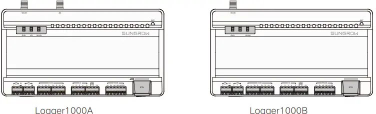
This manual is valid for the following data loggers.
- Logger1000A (4G version)
- Logger1000B (non-4G version)
The foregoing Loggers are referred to as the “Logger1000” for short unless otherwise specified.
Safety
- Contents may be periodically updated or revised due to product development. The information in this guide is subject to change without notice. In no case shall this guide substitute for the user manual or related notes on the device.
- Make sure to read over, fully understand and strictly follow the detailed instructions of the user manual and other related regulations. Scan the bottom QR Code of the cover to view or obtain the user manual.
- All operations can be performed only by qualified personnel, that must be trained in the installation and commissioning of the electrical system, as well as the dealing with hazards, have knowledge of the manual and of the local regulations and directives.
- Before installation, check that the package contents are intact and complete against the packing list. Contact SUNGROW or the distributor in case of any damaged or missing components.
- The cable must be intact and well-insulated. Operation personnel must wear proper personal protective equipment (PPE) all the time.
- Any violation could result in personal death or injury or device damage, and will void the warranty.
EU Declaration of Conformity within the scope of the EU directives
- Restriction of the use of certain hazardous substances 2011/65/EU and 2015/863/EU (RoHS)
- The Radio Equipment Directive 2014/53/EU (RED)
SUNGROW confirms herewith that the products described in this document are in compliance with the fundamental requirements and other relevant provisions of the abovementioned directives. The entire EU Declaration of Conformity can be found at support.sungrowpower.com.
Technical parameters listed above apply to EU countries only.
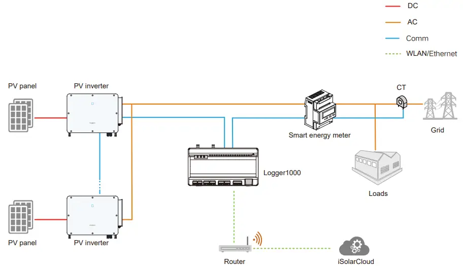
Typical Application
PV System
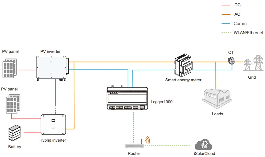
Energy Storage System
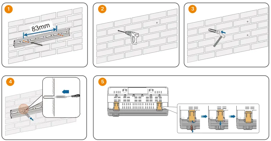
Mechanical Installation
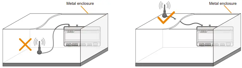
Installation Location

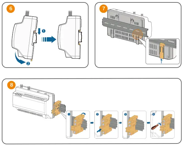
Guide Rail-Mounting
Installing Antenna
Installing Power Box

Electrical Connection
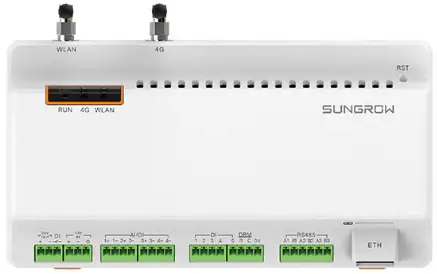
Port Introduction
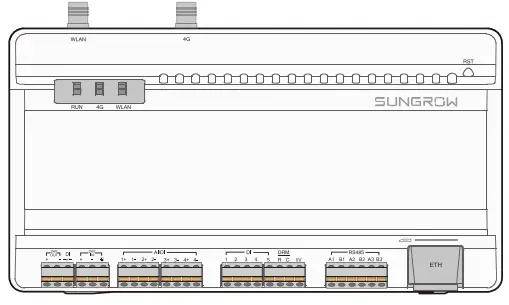
Port description
| Tab. 3-1 Port description | ||
| Port (print) | Function | Description |
| 24V OUT | 24V power output | 24V±5%, the max. output current: 0.5A |
| DI | Converters AI into DI | Switch for enabling the AI/DI function |
| 24V IN | 24V power input | 24V±3% |
| Grounding | Connecting protective grounding cable | |
| AI/DI | Analog input | Default AI input sampling: 0-10V or 4-20mA |
| DI | Digital input | Digital signal input |
| DRM | Demand Response Modes function | – |
| 0V | Digital reference point | – |
| RS485 | RS485 communication port | Support of 3 inputs of RS485 |
| SIM card slot | Support of Micro-SIM card | |
|
ETH |
Ethernet port |
Can be connected to background master via devices such as Ethernet switch and router |
| WLAN | WLAN antenna | |
| 4G* | 4G antenna | |
|
RST |
Reset |
Press and hold it for > 3s to restart. Press and hold it for > 60s to restore the default settings. |
Note: *Only the Logger1000A is equipped with the SIM card slot and the 4G function.
Indicator description
| Tab. 3-2 Indicator description | |||
| Indicator (print) | LED color | LED status | Description |
| Off | No external power supply connected | ||
| Slow flash (Green) | Normal running | ||
| Running indicator
(RUN) |
Red/green |
Slow flash (Red) |
Device alarm |
| Steady on (Red) | Logger1000 running fault | ||
| Off | No data communication | ||
| 4G indicator (4G)* | Blue | Steady on | 4G connected successfully |
| Slow flash | Data communication in process | ||
| Off | No data communication | ||
| WLAN indicator
(WLAN) |
Blue | Steady on | WiFi connected successfully |
| Slow flash | Data communication in process | ||
Note: * Only the Logger1000A is equipped with the 4G indicator.
Connection to PV Devices
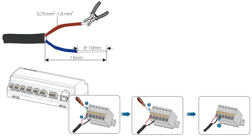
- Connection to a single inverter
The RS485 port of SUNGROW inverter is RS485 terminal block or RJ45 port. - RS485 terminal block connection

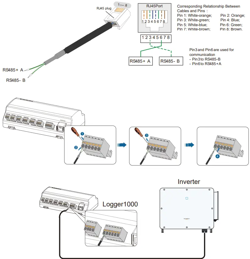
RJ45 port connection
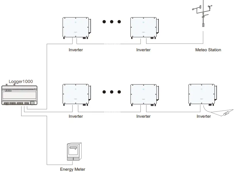
Connection to multiple devices
NOTICE
- Multiple inverters are connected to the Logger1000 in the RS485 daisy chain manner.
- If more than 15 inverters are connected on the RS485 bus, it is recommended to connect a 120Ω terminal resistor in parallel on the RS485A and RS485B lines at the head or tail end of the bus.
- When the number of device types is less than or equal to the number of RS485 ports of Logger1000, it is recommended to connect different types of devices to different RS485 ports separately.
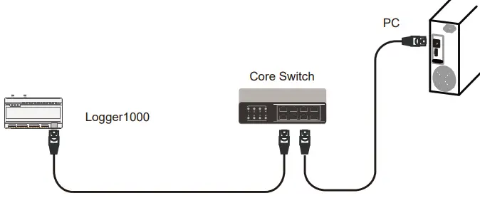
Connection to Background
NOTICE
Default IP address of the “ETH”: 12.12.12.12.
Connection to Micro-SIM/ Verbindung zur Micro-SIM
Micro-SIM card size: 12mm × 15mm.
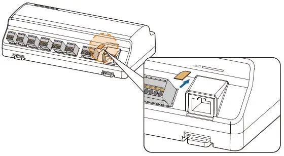
NOTICE
Micro-SIM card hot-plugging is supported.
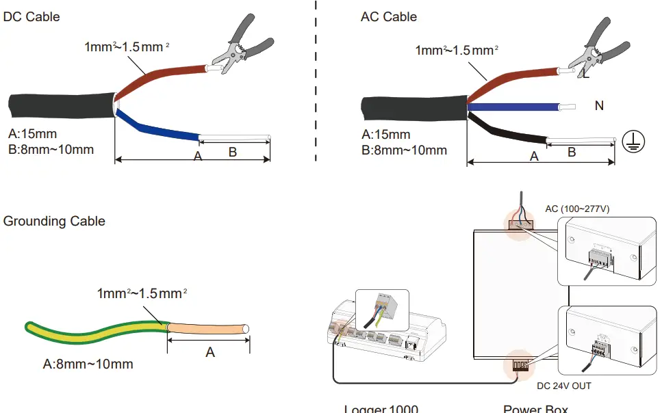
Connection to Power Box
Connection to Emergency Stop Device

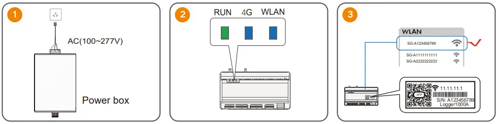
Commissioning

Security Declaration
- Support for software updates: 2 years
- For details on the product’s network security vulnerability response process and vulnerability disclosure, please scan the QR code on the right or visit the following website:
https://en.sungrowpower.com/security-vulnerability-management
User Manual of iSolarCloud App

More information in the QR code or at http://support.sungrowpower.com

Sungrow Power Supply Co., Ltd.
www.sungrowpower.com
Documents / Resources
 |
SUNGROW Logger 1000 Data Logger Smart Solar [pdf] Installation Guide Logger1000A, Logger1000B, Logger 1000 Data Logger Smart Solar, Logger 1000, Data Logger Smart Solar, Logger Smart Solar, Smart Solar, Solar |