1. Bubuka
This instruction manual provides detailed guidance for the assembly, operation, and maintenance of the Whadda WSRC8023 DIY Soldering Kit. This kit allows users to construct a 2-wire, 10-channel microprocessor-controlled remote control system, ideal for educational purposes and hobby electronics projects. Please read all instructions carefully before beginning assembly.
2. Émbaran Kasalametan
Working with electronics and soldering irons requires adherence to safety precautions. Failure to follow these guidelines may result in injury or damage to components.
- Salawasna damel di tempat anu ventilasina saé pikeun nyingkahan ngambekan haseup solder.
- Use appropriate eye protection (safety glasses) to shield against splashes or flying debris.
- Ensure your soldering iron is placed in a secure stand when not in use and is unplugged when unattended or finished.
- Avoid touching the hot tip of the soldering iron.
- Be aware of hot components after soldering. Allow them to cool before handling.
- Keep a fire extinguisher or fire blanket nearby.
- Always disconnect power before making any changes to the circuit.
- This kit contains small parts and is not suitable for young children without adult supervision.
3. Eusi Paket
Verify that all components listed below are present in your kit. Refer to the image for visual identification of parts.
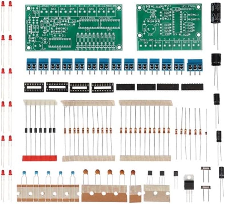
Image 3.1: All components included in the Whadda WSRC8023 DIY Soldering Kit, showing two green PCBs, various resistors, capacitors, LEDs, integrated circuits, terminal blocks, and an antenna wire.
- 2 x Printed Circuit Boards (PCBs) - 1 Transmitter, 1 Receiver
- Integrated Circuits (ICs) and Sockets
- Resistors (various values)
- Capacitors (electrolytic and ceramic)
- LED (Light Emitting Diodes)
- Blok Terminal
- Kristal
- Dioda
- Transistor
- Kawat Antenna
- Panyambung kakuatan
4. Parentah Majelis
Before starting, ensure you have the necessary tools: a soldering iron, solder, wire cutters, needle-nose pliers, and a multimeter (optional but recommended). Follow the silk-screened labels on the PCBs for component placement.
4.1 Tip Solder Umum
- Heat both the component lead and the PCB pad simultaneously.
- Apply a small amount of solder to the heated joint. It should flow smoothly and form a shiny, concave fillet.
- Remove the solder, then the iron.
- Trim excess leads with wire cutters.
4.2 Component Placement Order
It is generally recommended to solder components in order of height, starting with the lowest profile components first. This prevents taller components from obstructing access to smaller pads.
- Resistors and Diodes: Solder all resistors and diodes. Pay attention to the polarity of diodes (band indicates cathode).
- IC Sockets: Solder soket IC. Pastikeun takik dina soket sajajar jeung takik dina layar PCB.
- Ceramic Capacitors and Crystals: Solder these components. Ceramic capacitors typically do not have polarity.
- LEDs: Solder the LEDs. Note their polarity: the longer lead is typically the anode (+), and the shorter lead is the cathode (-). The flat side of the LED body usually indicates the cathode. Match this to the PCB marking.
- Electrolytic Capacitors: Solder electrolytic capacitors. These are polarized; the longer lead is positive (+), and the stripe on the body indicates the negative (-) lead. Match to the PCB markings.
- Transistor: Solder the transistors, ensuring their flat side or pinout matches the PCB silk screen.
- Terminal Blocks and Power Connector: Solder these connectors.
- Antenna Wire: Solder the antenna wire to the designated pad on the transmitter board.
- Lebetkeun IC: Carefully insert the Integrated Circuits into their respective sockets. Ensure the notch on the IC aligns with the notch on the socket and PCB. Bend the pins slightly inward if necessary to align with the socket holes.

Image 4.1: Fully assembled transmitter and receiver boards of the Whadda WSRC8023 remote control kit, connected by a coiled red and black wire.
5. Parentah Operasi
Once both the transmitter and receiver boards are fully assembled and inspected for soldering errors, you can proceed with operation.
- Sambungan Daya: Connect a suitable DC power supply (refer to specifications for voltage range) to the power input terminal on both the transmitter and receiver boards. Ensure correct polarity.
- Sambungan 2-Kawat: Connect the two output wires from the transmitter board to the corresponding input terminals on the receiver board. These are typically labeled for data transmission.
- Channel Activation: The transmitter board features input terminals for activating channels. By connecting these inputs to a common ground or positive voltage (depending on the design, refer to the schematic if provided), you can activate the corresponding output channels on the receiver board.
- Pemantauan Kaluaran: The receiver board will have output terminals (and possibly LEDs) that indicate the status of each channel. Connect your desired devices (e.g., relays, motors, other circuits) to these output terminals.
The 10-channel functionality allows for independent control of up to 10 different functions or devices via the 2-wire communication link.
6. Pangropéa
The Whadda WSRC8023 kit requires minimal maintenance once assembled correctly.
- Keep the boards clean and free from dust and debris. Use a soft brush or compressed air if necessary.
- Periodically inspect solder joints for any signs of cracking or corrosion, especially if the device is subjected to vibration or extreme temperatures. Re-solder any faulty joints.
- Ensure all wire connections to terminal blocks are secure.
- Store the assembled unit in a dry, cool environment.
7. Cara ngungkulan
If your remote control system is not functioning as expected, consider the following troubleshooting steps:
- Henteu aya kakuatan: Check power supply connections and polarity. Ensure the power supply is providing the correct voltage jeung ayeuna.
- No Channel Response: Verify the 2-wire connection between transmitter and receiver. Check for continuity in the wires. Ensure the correct input on the transmitter is being activated.
- Incorrect Channel Response: Double-check component placement and polarity, especially for ICs, diodes, and electrolytic capacitors. Inspect all solder joints for shorts or cold joints.
- Operasi intermittent: This can often be caused by cold solder joints or loose connections. Re-inspect all solder points and terminal block connections.
- Komponen Panas teuing: Immediately disconnect power. This usually indicates a short circuit or incorrect component placement. Carefully review the assembly steps and component polarities.
8. Spésifikasi
Key technical specifications for the Whadda WSRC8023 DIY Soldering Kit:
| Fitur | Spésifikasi |
|---|---|
| Nomer modél | WSRC8023 |
| Saluran | 10 |
| Tipe Kontrol | 2-Wire Microprocessor Controlled Remote |
| Dimensions (assembled, approx.) | 15.8 x 15.5 x 3.8 cm |
| Weight (assembled, approx.) | 141 g |
| Produsén | Velleman Grup nv |
| Batré Diperlukeun | No (external power supply required) |
9. Garansi jeung Rojongan
For warranty information and technical support regarding your Whadda WSRC8023 DIY Soldering Kit, please refer to the documentation provided by the retailer or visit the official Whadda/Velleman Group websitus. Simpen bukti pameseran anjeun pikeun klaim garansi.
For additional assistance, you may contact the manufacturer directly through their customer service channels.


