STMicroelectronics STSW-WBC2STUDIO Software

Introduction
- The purpose of this document is to provide a comprehensive user guide for the STSW-WBC2STUDIO software. It aims to provide clear instructions on how to install, execute, and use the features provided by the software.
- This document is intended for end-users of the STSW-WBC2STUDIO software, who have all the required hardware settings. The scope of this document is limited to the STSW-WBC2STUDIO software.
Abbreviations, acronyms, and definitions
Abbreviations, and acronyms
Table 1. List of abbreviations
| Abbreviation | Description |
| UART | Universal Asynchronous Receiver-Transmitter |
| HW | Hardware |
| NVM | Non-Volatile Memory |
| PRx | Power Receiver |
| PTx | Power Transmitter |
| Rx | Receiver/Receive. Unless explicitly mentioned, this is used interchangeably with PRx |
| Tx | Transmitter/Transmit. Unless explicitly mentioned, this is used interchangeably with PTx |
| UI | User Interface |
Definitions
Table 2. List of definition
| Name | Description |
| application processor | A microcontroller or microprocessor that controls the device of interest. Typically, an application processor is the main processor of the system or subsystem in which the device is connected to |
|
customer |
The person, or persons, who pay for the product and usually (but not necessarily) decide the requirements. In the context of this recommended practice, the customer and the supplier may be members of the same organization |
| host | A master system that controls the device of interest. In the case that the host is a microcontroller or microprocessor, it is referred to as an application processor |
| user | The person, or persons, who operate or interact directly with the product |
System requirements
Table 3. List of system requirements
| Description | Minimum requirement |
| Operating system | Microsoft® Windows® 10 |
| Processor | 1 Ghz processor |
| RAM | 4 GBytes or higher (Minimum 8 GB preferred for better performance, 16 GB recommended in debug mode) |
| Hard disk space | 15 Mbytes or more |
Software installation
STSW-WBC2STUDIO software does not require specific installation steps. To execute the software:
- Extract the contents of STSW-WBC2STUDIO Vx.x.x.zip into C driver
- Double-click on STSW-WBC2STUDIO.exe to launch the software In case of using ST-LINK as a USB-UART bridge, install USB driver.
Hardware connection
Before starting the software, ensure the target evaluation kit is connected to the PC via a USB-UART bridge and powered up. The Table 4. The list of supported USB-UART bridges shows a list of ST-LINK bridges supported by the STSW-WBC2STUDIO software.
The STSW-WBC2STUDIO can connect one USB-UART bridge at a time for UART serial communication.
The Table 5. List of supported WLC evaluation kit lists the WBC2 evaluation kit supported by the STSW‑WBC2STUDIO software.
Figure 1. STSW-WBC2STUDIO HW connection

Table 4. List of supported USB-UART bridge
| Part number | Description |
| STLINK-V3SET | USB-UART bridge |
| STLINK-V3MINI | USB-UART bridge |
| STLINK-V3MINIE | USB-UART bridge |
| USB-UART bridge | Generic USB-UART bridge |
Table 5. List of supported WLC evaluation kit
| Part number | PTx | Description |
| STEVAL-WBC2TX70 | PTx | General application PTx up to 70 W |
| STEVAL-WBC2TX50 | PTx | General application PTx up to 50 W |
Interface Description
The STSW-WBC2STUDIO main interface consists of three main sections: The top menu, the Side Menu Bar, and the Output Window.
The Side Menu Bar selects the output in the Output Window, details can be found in Section 5.2: Output Window. For details about the Top menu refer to Section 5.1: Top menu section.

Top menu section
The Top Menu Section hosts the interface to access the software’s setup, settings, and information about the software.

Table 6. Top menu UI element(s) description
| UI element(s) | Description |
| Expander | Allows users to expand and collapse the Side Menu bar. This feature allows the user to have a bigger view of the Output Window when needed |
| Connect | The toggle button allows you to connect or disconnect the WBC2 device |
| Settings | The Settings button opens the Settings window, for details refer to Section 5.1.1: Settings window |
| About | Opens the About window, for details refer to Section 5.1.2: About Window |
Settings window

Table 7. Settings Window UI element(s) Description
| UI Element(s) | Description |
|
Tx/Rx Settings |
Option to manually choose or auto-select com port for WBC2 UART
Option to choose WBC2 Param XML version |
|
Charts Settings |
Configures chart plotting features
Buffer size [large: 100, medium: 50, small: 10] plot entries Older data in plots are cleared to add new data when the plot entries exceed the configured size |
| Verbosity Settings | Enable traces based on category |
About Window

Table 8. About Window UI element(s) Description
| UI Element(s) | Description |
| Product Version | Software version number |
Output Window
Info
Info Window displays the main metrics of running the STWBC2 device.

Table 9. Info Window UI element(s) Description
| UI Element(s) | Description |
| Status Semaphore | Provides current status of Tx device |
| Event box | Display device status events. The clear button allows to clear events |
| Device Metrics | Device metrics indicate the current status of the device |
| Tx Info | Hardware and Firmware details of the Tx device |
| Rx Info | The last identified power receiver information |
| Input Power Supply | Current input power supply of Tx device |
Charts
Charts allow users to monitor key operational parameters in real-time. Chart settings are configurable in the Settings Window.
The maximum buffer size (period) available is 50 seconds. The data is plotted once every 500 ms and up to 4 different charts can be displayed at a time. The check box select option in Legend allows the user to choose charts for display. We recommend clearing the previously captured charts, using the Clear button, before starting a new capture.

Table 10. Charts Window UI element(s) Description
| UI Element(s) | Description |
| Start/Pause | The toggle button allows the user to start or pause sampling and plotting |
| Clear | Clear existing plot(s) |
| Save | Save the current plot into a .csv file |
| Plot Area | Shows one or multiple plots |
| Legend | Legend for plot area. Click on the check box to enable/disable plotting |
Table 11. Charts controller description
| Action | Gesture |
| Pan | Right mouse button |
| Zoom | Mouse wheel |
| Zoom by rectangle | Ctrl+Right mouse button, Middle mouse button |
| Reset | Ctrl+Right mouse button double-click, Middle mouse button double-click |
| Show ‘tracker’ | Left mouse button |
| Reset axes | ‘A’ , Home |
Parameters
The parameters page allows the user to configure the device and to save and load the prepared configuration.

Table 12. Parameters Window UI element(s) Description
| UI Element(s) | Description |
| Read | Read from the device RAM and display in GUI |
| Write | Write parameters configured in GUI to device RAM |
| Write NVM | Write parameters configured in GUI to device RAM and NVM |
| Save | Save Parameters to the configuration file |
| Load | Load parameter configuration file to GUI |
| Parameters Display | Display box for parameters in GUI |
Traces
Traces are used to monitor key operating parameters of the device and to keep track of ongoing firmware tasks.

Table 13. Traces Window UI element(s) description
| UI Element(s) | Description |
| Scroll | Enables auto-scrolling to the latest Trace log |
| Backup | Enables partial backup. When the trace buffer is full(2000 recordings), the traces are stored to the file and the Trace log is cleared |
| Start | The toggle button allows to Enable/disable trace logs to display. By default, traces shall be enabled |
| Clear | Clears Trace logs from the display |
| Save | Opens a dialog to save Trace logs to file, refer to Section 5.2.4.1: Traces save |
| Load | Loads of previously saved traces |
| Filter | Enables trace filter based on user selection |
| Information | Allows the user to click on individual traces for more details |
| Trace Log | Display box for traces |
Traces save
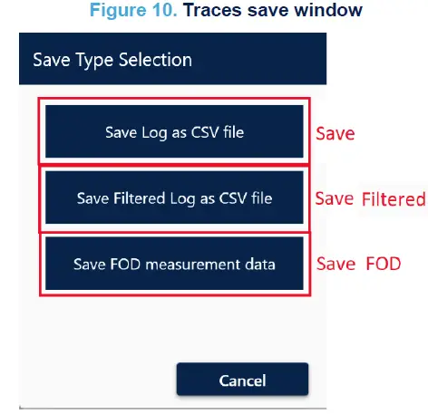
Table 14. Traces save window UI element(s) Description
| UI Element(s) | Description |
| Save | Save Trace logs to CSV file |
| Save Filtered | Save only filtered trace logs to the CSV file |
| Save FOD | Save traces to be used for FOD tuning |
FOD tuning
Details about FOD tuning are separately available in the respective application notes.
FW
FW Window enables the user to load and change the firmware of the device. This Window allows *.hex format firmware file.

Table 15. Programming Window UI element(s) Description
| UI Element(s) | Description |
| Load | Select the firmware source file *.hex |
| Write | Start programming firmware into the device NVM |
| Calibrate | To execute calibration manually. It is recommended to perform calibration after each firmware update |
| Read All | Allows users to read and save contents of the NVM (both firmware and Parameters) into a *.hex file. The generated file can also be used later in mass production |
Log
The Log Window displays logs of all the UART transactions performed during any session. These logs may be saved into a file.

Table 16. Log Window UI element(s) description
| UI Element(s) | Description |
| Debug | Enables log level up to debug |
| Clear | Clears the debug trace log |
| Save | Saves current trace log into a .txt file |
| Scroll | Enables auto-scrolling to the latest log |
| Backup | Enables partial backup when the log buffer is full |
| Log Trace | Display box for traces |
Revision history
Table 17. Document revision history
| Date | Revision | Changes |
| 09-Feb-2024 | 1 | Initial release. |
IMPORTANT NOTICE – READ CAREFULLY
- STMicroelectronics NV and its subsidiaries (“ST”) reserve the right to make changes, corrections, enhancements, modifications, and improvements to ST products and/or to this document at any time without notice. Purchasers should obtain the latest relevant information on ST products before placing orders. ST products are sold according to ST’s terms and conditions of sale in place at the time of order acknowledgment.
- Purchasers are solely responsible for the choice, selection, and use of ST products and ST assumes no liability for application assistance or the design of purchasers’ products.
- No license, express or implied, to any intellectual property right is granted by ST herein.
- Resale of ST products with provisions different from the information set forth herein shall void any warranty granted by ST for such product.
- ST and the ST logo are trademarks of ST. For additional information about ST trademarks, refer to www.st.com/trademarks. All other product or service names are the property of their respective owners.
- Information in this document supersedes and replaces information previously supplied in any prior versions of this document.
- © 2024 STMicroelectronics – All rights reserved
Documents / Resources
 |
STMicroelectronics STSW-WBC2STUDIO Software [pdf] User Guide UM3287, STSW-WBC2STUDIO Software, STSW-WBC2STUDIO, Software |