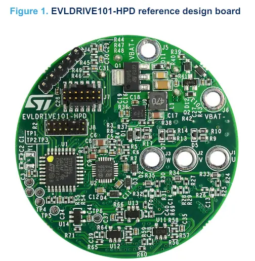
STMicroelectronics EVLDRIVE101-HPD Reference Design Board
Specifications
- Input voltage: Nominal from 18 V to 52 V
- Output current: Peak 21.15 A, Continuous 15 A rms
- Output power: Continuous 750 W
Product Information
Safety Precautions
Warning: Some components on the board could reach hazardous temperatures during operation. Follow these precautions:
- Do not touch components or the heatsink.
- Do not cover the board.
- Avoid contact with flammable materials or materials releasing smoke when heated.
- Allow the board to cool down after operation before touching it.
Hardware and Software Requirements
To use the board, you will need:
- A Windows PC
- An STLINK debugger/programmer for STM32 or equivalent
- Firmware example generated with MCSDK 6.2 or greater
- A power supply with an output voltage between 18 V and 52 V
- A three-phase brushless motor compatible with the power supply and board voltage ranges
Product Usage Instructions
Getting Started
- Connect brushless motor phases to J1, J2, and J3.
- Supply power through J5 (positive) and J6 (ground).
- Download compiled code through the SWD interface by connecting the STLINK programmer to J7.
- To program the MCU, supply control circuitry by shorting pin 5 of J8 to ground.
Hardware Description and Configuration
The board specifications are listed below:
| Parameter | Value |
|---|---|
| Input voltage | Nominal from 18 V to 52 V |
| Output current | Peak: 21.15 A, Continuous: 15 A rms |
| Output power | Continuous: 750 W |
FAQ
- Q: What should I do if the board gets too hot during operation?
A: If the board reaches hazardous temperatures, stop operation immediately and allow it to cool down before touching it. - Q: Can I use a power supply with an output voltage lower than 18 V?
A: It is recommended to use a power supply within the specified voltage range (18 V to 52 V) for optimal performance and safety.
UM3257
User manual
Getting started with the EVLDRIVE101-HPD compact reference design based on STDRIVE101 for high-current and brushless motor-driven tools
Introduction
The EVLDRIVE101-HPD is a three-phase extremely compact inverter for brushless motors based on the STDRIVE101 device in conjunction with the STM32G071KB microcontroller. The board is a ready-to-use and flexible solution ideal for battery-powered three-phase applications requiring high output currents.
It implements both three-shunt and single-shunt topologies and includes the following features:
- Operative voltage from 18 V to 52 V
- Output current up to 15 Arms
- Low consumption mode cutting the battery supply to the control stage
- Current limiter with adjustable reference
- VDS monitoring, undervoltage lockout, overcurrent, and protection against reverse biasing from power stage outputs
- Back-EMF (BEMF) sensing circuitry
- Input connector for encoder or Hall-effect based sensors
- Bus voltage monitoring and temperature monitoring
- 5 spare GPIOs
- SWD debug interface and direct firmware update through UART (DFU)
Safety precautions
Warning: Some of the components mounted on the board could reach hazardous temperatures during operation.
When using the board, follow these precautions:
- Do not touch the components or the heatsink.
- Do not cover the board.
- Do not put the board in contact with flammable materials or with materials releasing smoke when heated.
- After operation, allow the board to cool down before touching it.
Hardware and software requirements
To use the board, the following software and hardware are required:
- A Windows PC
- An STLINK debugger/programmer for STM32 or equivalent
- A 6-step or FOC firmware example generated with the MCSDK 6.2 or greater. To generate the code, the description of the board (JSON file) must be imported in the MSDK Workbench GUI, if not already present, through the Board Manager as indicated in the MSDK Workbench user manual. The description of the board can be downloaded from the web page of the EVLDRIVE101-HPD
- An IDE chosen among the IAR Embedded Workbench for Arm (IAR-EWARM), Keil® microcontroller development kit (MDK-ARM-STM32), and STM32CubeIDE (STM32CubeIDE)
- A power supply with an output voltage between 18 V and 52 V
- A three-phase brushless motor fitting the current and voltage ranges of both the power supply and the board
Getting started
To start your project with the board:
- Connect the brushless motor phases to J1, J2, and J3
- Supply the board through J5 (positive) and J6 (ground)
- Download the compiled code through the SWD interface connecting the STLINK programmer to J7 (STDC14 connector)
Note:
To program the MCU, the control circuitry must be supplied shorting the pin 5 of J8 to ground (that is, trigger switch closed). See Section 4.6 Turn-on/off circuitry for further details.
Hardware description and configuration
The ratings of the board are listed in Table 1 and Figure 2 shows the position of the connectors of the board.
Table 1. EVLDRIVE101-HPD specifications
| Parameter | Value | |
| Input voltage | Nominal | From 18 V to 52 V |
| Output current | Peak | 21.15 A |
| Continuous (1) | 15 A rms | |
| Output power | Continuous (1) | 750 W |
Actual continuous current may be limited by ambient temperature and thermal dissipation.

Table 2 lists the MCU GPIOs mapped on the J8 connectors.
Table 2. J8 pinouts
| Connector | Pin | Signal | Remarks |
| J8 | 1 | 5 V | 5 V supply |
| 2 | 3.3 V | 3.3 V supply | |
| 3 | Ground | ||
| 4 | Ground | ||
| 5 | Input trigger switch | Connect to ground to supply the control circuitry | |
| 6 | Not connected | ||
| 7 | PA6 | Optional potentiometer input 1 (ADC channel 6) | |
| 8 | PA12 | Current limiter comparator output |
| Connector | Pin | Signal | Remarks |
| J8 | 9 | PB2 | Optional potentiometer input 2 (ADC channel 10) |
| 10 | PB4 | Current limiter reference | |
| 11 | PB8 | Reserved GPIO for keep-alive circuit | |
| 12 | PB9 | ||
| 13 | PB7 | USART_RX | |
| 14 | PB6 | USART_TX |
Operation modes
- The EVLDRIVE101-HPD supports FOC and 6-step algorithms, both sensor-less and censored.
- According to the algorithm, the hardware configuration of the board must be modified as indicated in Table 3 and shown in Figure 3.
Table 3. EVLDRIVE101-HPD configuration
| Operation mode | Hardware changes |
| FOC Three shunts | Default – no changes are required |
| FOC Single shunt |
|
| 6-STEP Sensor-less Voltage-mode |
|
| 6-STEP Hall-sensors Voltage-mode | Default – no changes are required |
| 6-STEP Hall-sensors Current-mode |
|

Current sensing
The board mounts three shunt resistors to sense the current flowing into the motor phases. Each resistor is connected to an amplifier for signal conditioning before forwarding the sensed value to the ADC. Filtering parameters and the gain factor may be changed thanks to R59, R64, R69 and C38, C39, C40.
The STDRIVE101 integrates a comparator for overcurrent (OC) detection: its intervention is set changing the value of R4, R5, R6, and R7 (see Figure 4) according to Eq. (1).


Equation 1

Where
Rnet = RR54 = RR64 = RR74
VREF = 0.505V
The default threshold is set to 25.5 A.
Hall-effect sensors and encoder connector
The board allows motors with digital Hall-effect sensors or encoders to be interfaced with the board through connector J4.
The connector provides:
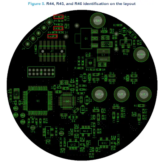
- Pull-up resistors (R44, R45, R46) for open-drain and open-collector interfacing. It is always recommended to remove the pull-up resistors in case of push-pull outputs (see Figure 5)
- 5 V supply generated by the voltage regulator integrated on the board
Table 4. J4 pinout
| Pin | Encoder | Hall-effect sensor |
| 1 | A+ | Hall 1 |
| 2 | B+ | Hall 2 |
| 3 | Z | Hall 3 |
| 4 | Encoder power supply | Sensor power supply |
| 5 | Ground | Ground |
BEMF sensing network
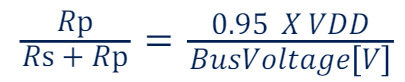
As shown in Figure 6, the board integrates a BEMF sensing network to allow sensor-less driving mode with a 6-step algorithm. Phase voltage VOUT is divided according to Eq. (2) before ADC conversion.
Equation 2

Note:
- It is advised that VADC does not exceed VDD to prevent GPIO damaging.
- On the other hand, the user should be aware that implementing a VADC / VOUT ratio much lower than needed, the BEMF signal may be too low and the control not robust enough. The recommended value is:

Current limiter
- The board integrates a current limiter to allow current driving mode with a 6-step algorithm and motors with Hall sensors. Configuring the board in single-shunt topology, the amplified current signal is compared to the reference (PB4) generated by a filtered PWM signal. The schematic is shown in Section 4.5.
- The current limiting feature is not available with 6-step sensor-less driving mode.

Turn-on/off circuitry
- An external switch placed between pin 5 of J8 and ground (pin 3 of J8) allows to connect and disconnect the control circuitry to the battery reducing the quiescent consumption to the lowest possible level.
- The schematic in Figure 8 shows the turn-on trigger circuitry. At power-up, Q1 PMOS is open and the battery is disconnected from the control circuitry. Closing the switch, the gate of the Q1 PMOS is forced low connecting the battery to the control circuitry.

Keep-alive circuit
- As soon as the Q1 PMOS connects the battery to the STM32G071KB, the MCU keeps the Q1 PMOS closed using the Q2 NMOS. In fact, it acts as an MCU driven switch in parallel to the external trigger switch.
- In this way, the firmware takes control of the connection between the battery and the control circuitry, allowing the code to perform a safe switch-off, for example, braking the motor.
- It is recommended to set the GPIO output controlling Q2 gate (PB8) at the very beginning of the MCU initialization.
- Detection of the status of the external trigger
- A dedicated circuit allows the monitoring of the actual status of the external trigger switch.
- The monitoring GPIO (PB5) is connected to the switch through the D13 diode. As long as the switch is closed, it forces the GPIO low through D13. Releasing the switch, D13 turns off and the GPIO returns high thanks to a pull-up resistor.
- When the MCU detects the opening of the switch, the braking and stopping procedure of the motor is started.
Protection against reverse biasing from power stage outputs
- As shown in the schematic diagram of Section 6, Figure 9, the battery is always connected to the power stage while the Q1 PMOS switch connects and disconnects the control circuitry. In this way, the voltage of the power stage outputs (VOUT) can be higher than the control logic supply (VM) violating the AMR limit of the gate driving circuitry: VOUT, max = VM + 2 V.
- The device is protected against this condition by means of the diodes between each output and the VM supply (D1, D2, D3, and D4).
Bill of materials
Table 5. EVLDRIVE101-HPD bill of materials
| Item | Qty | Ref. | Part/value | Description | Manufacture. | Order code |
| 1 | 5 | CI,C2,C38,C39 ,C40 | NM | SMT ceramic capacitor | ||
| 2 | 7 | C3,C19,C21,C 23,C28,C34,C4 1 | 100 nF | SMT ceramic capacitor | ||
| 3 | 5 | C4,C26, C35,C36,C37 | 1n | SMT ceramic capacitor | ||
| 4 | 2 | C5,C27 | 10n | SMT ceramic capacitor | ||
| 5 | 2 | C6,C17 | 1uF | SMT ceramic capacitor | ||
| 6 | 1 | C7 | 100n | SMT ceramic capacitor | ||
| 7 | 1 | C8 | 220 nF | SMT ceramic capacitor | ||
| 8 | 1 | C9 | 4.7uF | SMT ceramic capacitor | ||
| 9 | 5 | C10,C11,C12,C 20,C22 | 1uF | SMT ceramic capacitor | ||
| 10 | 3 | C13,C14,C15 | NM | SMT ceramic capacitor | ||
| 11 | 1 | C16 | 470 nF | SMT ceramic capacitor | ||
| 12 | 1 | C18 | 2.2uF | SMT ceramic capacitor | ||
| 13 | 1 | C24 | 4.7 u | SMT ceramic capacitor | ||
| 14 | 1 | C25 | 220n | SMT ceramic capacitor | ||
| 15 | 3 | C29,C30,C31 | 2.2 nF | SMT ceramic capacitor | ||
| 16 | 2 | C32,C33 | 220 u | Through hole aluminum elect. capacitor | Panasonic | ECA2AM221 |
| 17 | 6 | D1,D2,D3,D4,D 12,D13 | 1N4148WS | Small signal fast switching diode | Vishay | 1N4148WS-E3-08 / -E3-18 or equivalent |
| 18 | 6 | D5,D6,D7,D8,D 9,D10 | BAT30 | Small signal Schottky diode | STMicroelectronics | BAT30KFILM |
| 19 | 1 | D11 | BZT585B12T | SMD precision Zener diode | Diodes Incorporated | BZT585B12T or equivalent |
| 20 | 5 | J1,J2,J3,J5,J6 | pad200hole118_11 | |||
| 21 | 1 | J4 | STRIP 1×5 | Strip connector 5 poles, 2.54 mm | ||
| 22 | 1 | J7 | STDC14 | Connector header SMD 14POS 1.27 mm | Samtec | FTSH-107-01-L-DV-K-A |
| Item | Qty | Ref. | Part/value | Description | Manufact. | Order code |
| 23 | 1 | J8 | STRIP 2×7 | Strip connector 7×2 poles, 1.27 mm | NP | |
| 24 | 1 | L1 | 47uH | Inductor, shielded, 47 uH, 580 mA, SMD | Wurth Elektronik | 744031470 |
| 25 | 2 | NTC1, NTC2 | 10k | NTC thermistor | Vishay | NTCS0603E3103FMT |
| 26 | 1 | Q1 | STN3P6F6 | P-channel -60 V,
0.13 Ohm, -3 A STripFET F6 power MOSFET |
STMicroelectronics Diodes Incorporated | STNP6F6 DMP6023LE-13 |
| 27 | 1 | Q2 | 2N7002 | N-channel 60 V, 7.5 Ohm MOSFET | Diodes Inc. | 2N7002 or equivalent |
| 28 | 2 | R1,R43 | 39k | SMT resistor | ||
| 29 | 4 | R2,R36,R37,R 38 | 100k | SMT resistor | ||
| 30 | 1 | R3 | 22k | SMT resistor | ||
| 31 | 1 | R4 | 7.32k | SMT resistor | ||
| 32 | 3 | R5,R6,R7 | 3.3k | SMT resistor | ||
| 33 | 5 | R8,R59,R64,R 69,R71 | 10k | SMT resistor | ||
| 34 | 6 | R9,R11,R13,R1 5,R17,R19 | 100 | SMT resistor | ||
| 35 | 6 | R10,R12,R14, R16,R18,R20 | 39 | SMT resistor | ||
| 36 | 3 | R21,R22,R23 | 0.01 | SMT resistor | Bourns | CRA2512-FZ-R010ELF |
| 37 | 3 | R24,R27,R30 | 68k | SMT resistor | ||
| 38 | 3 | R25,R28,R31 | 4.3k | SMT resistor | ||
| 39 | 3 | R26,R29,R32 | NM | SMT resistor | ||
| 4 | 3 | R33,R34,R35 | 10 R | SMT resistor | ||
| 41 | 2 | R39,R40 | 150k | SMT resistor | ||
| 42 | 1 | R41 | 30k | SMT resistor | ||
| 43 | 1 | R42 | 100k | SMT resistor | ||
| 44 | 6 | R44,R45,R46, R47,R48,R49 | 1k | SMT resistor | ||
| 45 | 2 | R51,R53 | 910 | SMT resistor | ||
| 46 | 1 | R54 | 91k | SMT resistor | ||
| 47 | 1 | R55 | 5.6k | SMT resistor | ||
| 48 | 3 | R56,R61,R66 | 20k | SMT resistor | ||
| 49 | 6 | R57,R58,R62, R63,R67,R68 | 1.4k | SMT resistor | ||
| 50 | 3 | R60,R65,R70 | 0R | SMT resistor | ||
| 51 | 2 | SB1,SB2 | SOLDER_JUMPER1x3 | Jumper | ||
| 52 | 6 | TP1,TP2,TP3,T P4,TP5,TP6 | TP-Pad diam1_5mm | Test point – Pad 1.5 mm diameter |
| Item | Qty | Ref. | Part/value | Description | Manufact. | Order code |
| 53 | 1 | U1 |
STM32G071KBT3 |
Microcontroller Arm Cortex-M0+ MCU, 128 KB
flash, 36 KB RAM, 64 MHz CPU |
STMicroelectronics | STM32G071KBT3 |
| 54 | 1 | U2 | STDRIVE101 | Three-phase gate driver | STMicroelectronics | STDRIVE101 |
| 55 | 6 | U3,U4,U5,U6,U 7,U8 | STL220N6F7 | N-channel 60 V, 1.2 mO typ., 120 A STripFET F7 power MOSFET | STMicroelectronics | STL220N6F7 |
| 56 | 1 | U9 | L7983PU50R | 60 V 300 mA
synchronous step- down switching regulator |
STMicroelectronics | L7983PU50R |
| 57 | 1 | U10 | LDL112PU33R | 1.2 A low quiescent current LDO | STMicroelectronics | LDL112PU33R |
| 58 | 4 | U11,U12,U13,U 14 | TSV991ILT | Wide-bandwidth (20 MHz) rail to rail input/output 5 V CMOS op amp | STMicroelectronics | TSV991ILT |
| 59 | 1 | Y1 | NM | Crystal 32.768 kHz 12.5 PF SMD | NDK | NX3215SA-32.768K- STD-MUA-8 |
| 60 | 1 | Jumper 2 poles 1.27 mm | Wurth Elektromik | 622002115121 |
Schematic diagram


Figure 11. EVLDRIVE101-HPD schematic: power supply conversion


Figure 12. EVLDRIVE101-HPD schematic: inputs and outputs


Revision history
Table 6. Document revision history
| Date | Version | Changes |
| 11-Dec-2023 | 1 | Initial release. |
IMPORTANT NOTICE – READ CAREFULLY
- STMicroelectronics NV and its subsidiaries (“ST”) reserve the right to make changes, corrections, enhancements, modifications, and improvements to ST products and/or to this document at any time without notice. Purchasers should obtain the latest relevant information on ST products before placing orders. ST products are sold pursuant to ST’s terms and conditions of sale in place at the time of order acknowledgment.
- Purchasers are solely responsible for the choice, selection, and use of ST products and ST assumes no liability for application assistance or the design of purchasers’ products.
- No license, express or implied, to any intellectual property right is granted by ST herein.
- Resale of ST products with provisions different from the information set forth herein shall void any warranty granted by ST for such product.
- ST and the ST logo are trademarks of ST. For additional information about ST trademarks, refer to www.st.com/trademarks. All other product or service names are the property of their respective owners.
- Information in this document supersedes and replaces information previously supplied in any prior versions of this document.
- © 2023 STMicroelectronics – All rights reserved
UM3257 – Rev 1
Documents / Resources
 |
STMicroelectronics EVLDRIVE101-HPD Reference Design Board [pdf] User Manual EVLDRIVE101-HPD Reference Design Board, EVLDRIVE101-HPD, Reference Design Board, Design Board, Board |


