Sonic Driver Modbus-UFM WALL-UFM Modbus RTU Slave Meter

Product Information
Product Name: MODBUS WALL-UFM, Modbus RTU Slave Meter
Version: 2.1
Manufacturer: Sonic Driver Ltd
Copyright: 2023
Country of Origin: Made in Britain
Introduction
The MODBUS WALL-UFM is a Modbus RTU Slave Meter designed for various applications. It supports communication via RS485 and ballows users to interact with the meter using Modbus commands.
Mode
The meter operates in Modbus RTU mode.
Baud rate
The RS485 baud rate is set to 19200.
Parity
The RS485 parity is set to Even.
Stop Bits
The RS485 stop bits are set to 1.
Modbus Address
The Modbus-UFM Slave address is programmable and can be set from 1 to 255. The default Slave address is 1.
Data bits
The RS485 serial data is fixed at 8 bits.
Register format
In the UFM, each Modbus register is a 16-bit word, consisting of two 8-bit bytes. Register data in Modbus messages are packed as 2 bytes per register. The binary contents are right justified in each byte, with the high order bits in the first byte and the low order bits in the second byte.
Representation of floating-point values
The UFM stores floating-point values in IEEE 754 single precision format. The bus Master can access floating-point values from different register tables, each representing a different byte order. The user can determine the appropriate byte order by reading the first 2 registers of each table and comparing them to a fixed test value of 1234.0.
Modbus Commands
The UFM supports the following Modbus commands:
Read Holding Registers (Function Code: 03)
This command is used to read 2 to 110 contiguous holding registers from the UFM. The registers are addressed starting at zero, so holding registers numbered 1-110 are addressed as 0-109.
Read Input Registers (Function Code: 04)
This command is used to read 2 to 110 contiguous input registers from the flowmeter. The registers are addressed starting at zero, so input registers numbered 1-110 are addressed as 0-109.
Product Usage Instructions
Physical Connection
Connect the UFM board to the 2-wire bus using the screw terminals labeled ‘A’ and ‘B’. Note that some equipment manufacturers may label their terminals differently, such as ‘+’ and ‘-‘, so ensure the correct order of wire connection.
Cable Screen Connection
If necessary, connect the cable screen to the screw terminal provided on either the Master or Slave UFM.
Setting Baud Rate
Set the RS485 baud rate to 19200.
Setting Parity
Set the RS485 parity to Even.
Setting Stop Bits:
Set the RS485 stop bits to 1.
Setting Modbus Address:
The Modbus-UFM Slave address is programmable. Set the desired address from 1 to 255. The default Slave address is 1.
For more detailed information on communication software, communication command structure, UFM register map, and command definitions, refer to the user manual provided in the product package.
Introduction
Modbus RTU Slave functionality is implemented on the Sonic Driver on MODBUS WALL ultrasonic flowmeter (MODBUS WALL-UFM).
Meter settings are fully configurable on the UFM using a Windows based program running on a PC or laptop or an Android app running on a mobile phone. In addition a full range of flow measurements and diagnostics can be read from the meter.
Once installed and commissioned the computer or mobile can be disconnected and the meter wired back to a control room PCL or similar.
Mode
The Modbus RTU protocol is implemented over RS485 hardware.
Mobile connection uses a USB-OTG cable and Modbus interface. PC connection uses a USB A/B cable and a Modbus interface, see figure(1).
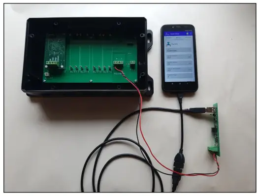
Figure(1) Mobile and PC connections
Physical connection to the 2-wire bus is via the screw terminals on the UFM board. The terminals are labelled ‘A’ and ‘B’.
Note that some equipment manufacturers label their terminals in other ways, e.g. ‘+’ and ‘-‘ so the exact order that the wires are connected may be reversed.
There is also a screw terminal for connection of cable screen. This may be connected at either the Master or the Slave UFM if necessary.
Baud rate
The RS485 baud rate is 19200.
Parity
The RS485 parity is Even.
Stop Bits
The RS485 stop bits is 1.
Modbus Address
The Modbus-UFM Slave address is programmable from 1 to 255.
The default Slave address is set to 1.
Data bits
RS485 serial data is fixed at 8 bits.
Register format
In the UFM each Modbus register is a 16-bit word, consisting of two 8-bit bytes.
Register data in Modbus messages are packed as 2 bytes per register. The binary contents are right justified in each byte. For each register the first byte contains the high order bits and the second byte contains the low order bits.
A floating-point number is stored as 32 bits using 4 bytes and therefore occupies 2 Modbus registers.
Representation of floating-point values
The UFM stores floating point values in IEEE 754 single precision format.
The bus Master accesses a floating-point value from any one of 4 different register tables. Each register table represents a different byte order.
Table start :Byte order: Common Description
- 0x0000: 1,0,3,2 :Floating-point Little-Endian with byte swap (Default)
- 0x1000: 0,1,2,3 :Floating-point Little-Endian Format
- 0x2000: 3,2,1,0: Floating-point Big-Endian Format
- 0x3000 :2,3,0,1 :Floating point Big-Endian with byte swap
By reading the first 2 registers of each table the user can determine which format matches their system when a fixed test value of 1234.0 is received.
Modbus Commands
The UFM implements Modbus commands 03, 04, 06 and 16.
Read Holding Registers 03
This function code is used to read from 2 to 110 contiguous holding registers from the UFM. Registers are addressed starting at zero. Therefore holding registers numbered 1-110 are addressed as 0-109.
The Modbus Master specifies a start address and register count.
Read Input Registers 04
This function code is used to read from 2 to 110 contiguous input registers from the flowmeter. Registers are addressed starting at zero. Therefore input registers numbered 1-110 are addressed as 0-109.
The Modbus Master specifies a start address and register count.
Write Single Register 06
This function code is used to write a single register. This function code is used to program integer values in the UFM.
The Master specifies an address and 16-bit data value for write.
The value is an unsigned 16-bit value. Valid values are defined for each register address, see appendix 3
Writing a value of 0x00 to register 60011 will clear the unit’s internal error log.
Write Single Register 16
This function code is used to write multiple registers. This function code is used to program 32-bit floating-point values in the UFM.
The Master specifies an address and 32-bit data value for write.
The value is a pair of unsigned 16-bit values. Valid values are defined for each register address, see appendix 3.
Broadcast address
The UFM supports broadcast address 0.
In broadcast address mode the Modbus master can send a command to all slaves.
No response is sent by the slaves.
Communications Software
There are several communications programs available for download online.
The UFM has been tested using Modbus Poll (for Windows platform) and Modbus Monitor (for Android and Windows platforms).
Appendix 1: Communication Command Structure
| Read holding registers | ||
| Slave ID | (1 byte) | |
| Function | (1 byte=03H) | |
| Start Address | (2 bytes) | |
| No. of Registers R | (2 bytes) | |
| CRC code | (2 bytes) | |
| Reply | ||
| Slave ID | (1 byte) | |
| Function | (1 byte) | |
| N = 2R | Byte Count N | (1 byte) |
| Hex Data | (N bytes) | |
| CRC code | (2 bytes) | |
| Read input registers | ||
| Slave ID | (1 byte) | |
| Function | (1 byte=04H) | |
| Start Address | (2 bytes) | |
| No. of Registers R | (2 bytes) | |
| CRC code | (2 bytes) | |
| Reply | ||
| Slave ID | (1 byte) | |
| Function | (1 byte) | |
| N = 2R | Byte Count N | (1 byte) |
| Hex Data | (N bytes) | |
| CRC code | (2 bytes) | |
| Write single register | Slave ID | (1 byte) |
| Function | (1 byte=06H) | |
| Start Address | (2 bytes) | |
| Hex Data | (2 bytes) | |
| CRC code | (2 bytes) | |
| Write multiple registers | Slave ID | (1 byte) |
| Function | (1 byte=10H) | |
| Start Address | (2 bytes) | |
| No. of Registers R | (2 bytes) | |
| N = 2R | Hex Data | (N bytes) |
| CRC Code | (2 bytes) | |
Appendix 2: Command 03 and 04 UFM Register Map
| Modbus Address | Measurement/Variable | Bytes | Format |
| 40001 | Fixed test pattern 1234.0 | 4 | IEEE |
| 40002 | |||
| 40003 | Flow Velocity (m/s) | 4 | IEEE |
| 40004 | |||
| 40005 | Flow Rate Volumetric (l/min) | 4 | IEEE |
| 40006 | |||
| 40007 | Flow Rate Mass (kg/min) | 4 | IEEE |
| 40008 | |||
| 40009 | Flow Rate Heat (KJ/s) | 4 | IEEE |
| 40010 | |||
| 40011 | Amplifier gain (dB) | 4 | IEEE |
| 40012 | |||
| 40013 | Signal Amplitude (dB) | 4 | IEEE |
| 40014 | |||
| 40015 | Signal Noise (dB) | 4 | IEEE |
| 40016 | |||
| 40017 | SNR (dB) | 4 | IEEE |
| 40018 | |||
| 40019 | Delta Time Difference (ns) | 4 | IEEE |
| 40020 | |||
| 40021 | Upstream Transit Time (us) | 4 | IEEE |
| 40022 | |||
| 40023 | Downstream Transit Time (us) | 4 | IEEE |
| 40024 | |||
| 40025 | Arrival Bin | 4 | IEEE |
| 40026 | |||
| 40027 | Signal Quality 1 (us) | 4 | IEEE |
| 40028 | |||
| 40029 | Signal Quality 2 (ADU) | 4 | IEEE |
| 40030 | |||
| 40031 | Meter Error Code | 4 | IEEE |
| 40032 | |||
| 40033 | Transducer Type (List) | 4 | IEEE |
| 40034 | |||
| 40035 | Transducer Wedge Angle (deg) | 4 | IEEE |
| 40036 | |||
| 40037 | Transducer SOS at 20 deg C (m/s) | 4 | IEEE |
| 40038 | |||
| 40039 | Transducer SOS at 60 deg C (m/s) | 4 | IEEE |
| 40040 | |||
| 40041 | Transducer Crystal Offset (m) | 4 | IEEE |
| 40042 | |||
| 40043 | Transducer Spacing Offset (m) | 4 | IEEE |
| 40044 |
| 40045 | Transducer Frequency Code (List) | 4 | IEEE |
| 40046 | |||
| 40047 | Transducer Delta Time Offset(ns) | 4 | IEEE |
| 40048 | |||
| 40049 | Transducer K Factor | 4 | IEEE |
| 40050 | |||
| 40051 | Pipe Type (List) | 4 | IEEE |
| 40052 | |||
| 40053 | Pipe SOS (m/s) | 4 | IEEE |
| 40054 | |||
| 40055 | Pipe Outer Diameter (m) | 4 | IEEE |
| 40056 | |||
| 40057 | Pipe Wall Thickness (m) | 4 | IEEE |
| 40058 | |||
| 40059 | Pipe Inner Wall Roughness (m) | 4 | IEEE |
| 40060 | |||
| 40061 | Fluid Type (List) | 4 | IEEE |
| 40062 | |||
| 40063 | Fluid Temperature (deg C) | 4 | IEEE |
| 40064 | |||
| 40065 | Fluid SOS (m/s) | 4 | IEEE |
| 40066 | |||
| 40067 | Fluid Density (kg/m3) | 4 | IEEE |
| 40068 | |||
| 40069 | Fluid Kinematic (cSt) | 4 | IEEE |
| 40070 | |||
| 40071 | Fluid SHC (J/(kg.K)) | 4 | IEEE |
| 40072 | |||
| 40073 | Flow Minimum Cut-off (m/s) | 4 | IEEE |
| 40074 | |||
| 40075 | Flow Damping (s) | 4 | IEEE |
| 40076 | |||
| 40077 | Modbus Address | 4 | IEEE |
| 40078 | |||
| 40079 | Corrected SOS (m/s) | 4 | IEEE |
| 40080 | |||
| 40081 | Window Delay (us) | 4 | IEEE |
| 40082 | |||
| 40083 | Zero Tracking (On/Off) | 4 | IEEE |
| 40084 | |||
| 40085 | Zero Calibration (On/Off) | 4 | IEEE |
| 40086 | |||
| 40087 | Dynamic Temperature (On/Off) | 4 | IEEE |
| 40088 | |||
| 40089 | Inlet Temperature (deg C) | 4 | IEEE |
| 40090 | |||
| 40091 | Outlet Temperature (deg C) | 4 | IEEE |
| 40092 | |||
| 40093 | Flow Profile K Factor | 4 | IEEE |
| 40094 | |||
| 40095 | Reynolds Number | 4 | IEEE |
| 40096 | |||
| 40097 | Number of Passes | 4 | IEEE |
| 40098 | |||
| 40099 | Tup Method | 4 | IEEE |
| 40100 | |||
| 40101 | Transducer Spacing (m) | 4 | IEEE |
| 40102 | |||
| 40103 | ATA/ETA (%) | 4 | IEEE |
| 40104 | |||
| 40105 | Iout Minimum Value (l/min) | 4 | IEEE |
| 40106 | |||
| 40107 | Iout Maximum Value (l/min) | 4 | IEEE |
| 40108 | |||
| 40109 | Relay Alarm Value (l/min) | 4 | IEEE |
| 40110 | |||
| 40111 | Interval On/Off | 4 | IEEE |
| 40112 | |||
| 40113 | NA | 4 | IEEE |
| 40114 | |||
| 40115 | NA | 4 | IEEE |
| 40116 | |||
| 40117 | NA | 4 | IEEE |
| 40118 | |||
| 40119 | Positive Volumetric Total (l) | 4 | IEEE |
| 40120 | |||
| 40121 | Negative Volumetric Total (l) | 4 | IEEE |
| 40122 | |||
| 40123 | Net Volumetric Total (l) | 4 | IEEE |
| 40124 |
Text Strings, company name (26 chars), model code (26 chars), serial number (8 chars), HW/SW version (6 chars)
| Modbus Address | Text Strings, 2 chars | Bytes | Format |
| 40300 | So | 2 | Word |
| 40301 | ni | 2 | Word |
| 40302 | c< > | 2 | Word |
| 40303 | Dr | 2 | Word |
| 40304 | Iv | 2 | Word |
| 40305 | er | 2 | Word |
| 40306 | < >< > | 2 | Word |
| 40307 | < >< > | 2 | Word |
| 40308 | < >< > | 2 | Word |
| 40309 | < >< > | 2 | Word |
| 40310 | < >< > | 2 | Word |
| 40311 | < >< > | 2 | Word |
| 40312 | < >< > | 2 | Word |
| 40313 | MO | 2 | Word |
| 40314 | DB | 2 | Word |
| 40315 | US | 2 | Word |
| 40316 | < >W | 2 | Word |
| 40317 | AL | 2 | Word |
| 40318 | L- | 2 | Word |
| 40319 | UF | 2 | Word |
| 40320 | M< > | 2 | Word |
| 40321 | ST | 2 | Word |
| 40322 | D< > | 2 | Word |
| 40323 | < >< > | 2 | Word |
| 40324 | < >< > | 2 | Word |
| 40325 | < >< > | 2 | Word |
| 40326 | 10 | 2 | Word |
| 40327 | 00 | 2 | Word |
| 40328 | 00 | 2 | Word |
| 40329 | 00 | 2 | Word |
| 40330 | 20 | 2 | Word |
| 40331 | 02 | 2 | Word |
| 40332 | 00 | 2 | Word |
Serial number in the example is 1000000, HW and SW versions are 2.00 and 2.00.
Signal Data Trace Values, as pairs of 8-bit values.
| Modbus Address | Signal Data Trace Value Pairs | Bytes | Format |
| 40401 | 8-bit data point 0, 8-bit data point 1 | 2 | WORD |
| 40402 | 8-bit data point 2, 8-bit data point 3 | 2 | WORD |
| 40403 | 8-bit data point 4, 8-bit data point 5 | 2 | WORD |
| 40404 | 8-bit data point 6, 8-bit data point 7 | 2 | WORD |
| 40405 | 8-bit data point 8, 8-bit data point 9 | 2 | WORD |
| 40406 | 8-bit data point 10, 8-bit data point 11 | 2 | WORD |
| .. | …,… | .. | … |
| .. | …,… | .. | … |
| 40649 | 8-bit data point 496, 8-bit data point 497 | 2 | WORD |
| 40650 | 8-bit data point 498, 8-bit data point 499 | 2 | WORD |
Appendix 3: Command 06 and 16 Definitions
| Write Single | Write Multiple | 16/32 bit Write | Value | Default | Minimum | Maximum | SI Unit | ||
| Value | CMD 06 | CMD 16 | |||||||
| Transducer Type | 0 | 16 | 1 | 1 | 0 | 3 | List | DN40/DM10/DM20/DS10 | |
| Transducer Wedge Angle | 0 | 32 | 40.000 | 40.000 | 1.000 | 90.000 | deg | ||
| Transducer SOS at 20degC | 2 | 32 | 2522.000 | 2522.000 | 500.000 | 7000.000 | m/s | ||
| Transducer SOS at 60degC | 4 | 32 | 2522.000 | 2522.000 | 500.000 | 7000.000 | m/s | ||
| Transducer Crystal Offset | 6 | 32 | 0.012 | 0.012 | 0.001 | 0.100 | m | ||
| Transducer Spacing Offset | 8 | 32 | 0.030 | 0.030 | 0.001 | 0.100 | m | ||
| Transducer Transmit Code | 1 | 16 | 1 | 1 | 0 | 2 | 4/1/2 MHz | ||
| Transducer Delta Transit Time Offset | 10 | 32 | 0 | 0 | -2.00E-08 | 2.00E-08 | s | ||
| Transducer K Factor | 12 | 32 | 1.000 | 1.000 | 0.001 | 1000.000 | |||
|
Pipe Type |
2 |
16 |
0 |
0 |
0 |
6 |
List |
Carbon Steel/Stainless Steel/Copper/PVC/Cast Iron/Ductile Iron/HDPE | |
| Pipe SOS | 14 | 32 | 3230.0 | 3230.0 | 500.0 | 7000.0 | m/s | ||
| Pipe Outer Diameter | 16 | 32 | 0.0606 | 0.0606 | 0.01 | 6.50 | m | ||
| Pipe Wall Thickness | 18 | 32 | 0.0032 | 0.0032 | 0.0005 | 0.1 | m | ||
| Pipe Inner Wall Roughness | 20 | 32 | 0.00001 | 0.00001 | 0.000001 | 0.002 | m | ||
| Fluid Type | 3 | 16 | 0 | 0 | 0 | 3 | List | Water/Petrol/Diesel/Glycol-Water | |
| Fluid Temperature | 22 | 32 | 18.000 | 18.000 | 0.000 | 150.000 | deg C | ||
| Fluid SOS | 24 | 32 | 1475.000 | 1475.000 | 50.000 | 3000.000 | m/s | ||
| Fluid Density | 26 | 32 | 998.520 | 998.520 | 50.000 | 3000.000 | kg/m2 | ||
| Fluid Kinematic | 28 | 32 | 1.080 | 1.080 | 0.001 | 40000.000 | cSt | ||
| Fluid Specific Heat Capacity | 30 | 32 | 4184.000 | 4184.000 | 10.000 | 10000.000 | J/(g.K) | ||
| Minimum Flow Cut Off | 32 | 32 | 0.025 | 0.025 | 0.000 | 1.000 | m/s |
| Flow damping | 4 | 16 | 10 | 10 | 0 | 255 | s | ||
| Modbus Address | 5 | 16 | 1 | 1 | 1 | 255 | |||
| Transducer Wedge Corrected SOS | 34 | 32 | 2522.000 | 2522.000 | 500.000 | 7000.000 | m/s | ||
| Sampling Window delay | 6 | 16 | 169 | 169 | 11 | 65535 | us | ||
| Zero Tracking On/Off | 7 | 16 | 1 | 1 | 0 | 1 | On/Off | ||
| Zero calibration On/Off | 8 | 16 | 0 | 0 | 0 | 1 | On/Off | ||
| Dynamic Temperature On/Off | 9 | 16 | 0 | 0 | 0 | 1 | On/Off | ||
| Number of Passes | 10 | 16 | 4 | 4 | 1 | 16 | |||
| Tup Method | 12 | 16 | 3 | 3 | 0 | 4 | List | Method 0, 1, 2, 3, 4 | |
| Iout Minimum Value | 36 | 32 | 0 | 0 | -1000000.0 | 1000000.0 | l/min | ||
| Iout Maximum Value | 38 | 32 | 160.0 | 160.0 | -1000000.0 | 1000000.0 | l/min | ||
| Relay Alarm Value | 40 | 32 | 40.0 | 40.0 | -1000000.0 | 1000000.0 | l/min | ||
| Interval On/Off | 13 | 16 | 0 | 0 | 0 | 5 | On/Off | 0 – Off, 5 – On | |
Documents / Resources
 |
Sonic Driver Modbus-UFM WALL-UFM Modbus RTU Slave Meter [pdf] Instruction Manual 40092, 40093, Modbus-UFM, WALL-UFM Modbus RTU Slave Meter, Modbus-UFM WALL-UFM Modbus RTU Slave Meter, Modbus RTU Slave Meter, RTU Slave Meter, Slave Meter, Meter |


