
SOLITY MT-100C Thread Interface Module

Features
Solity’s MT-100C is an interface board/accessory product that uses Wireless Thread communication. MT-100C is designed to easily implement IoT in an attachable manner on basic door locks.
| Items | Features |
|
Core MCU |
Cortex-M33, 78MHz @ Maximum Operating Frequency |
| 1536 KB @Flash, 256 KB @RAM | |
| Secure Vault (Secure Boot, TRNG, Secure Key Management, etc…) | |
|
Wireless |
Matter non-FHSS |
| -105 dBm @ Sensitivity | |
| Modulation: GFSK | |
|
Operating Condition |
1.3uA @ Deep Sleep Mode |
| 5mA @ RX Mode Current | |
| 19 mA @10dBm Output Power | |
| 160 mA @ 20dBm Output Power | |
| 5 V @ Operating Voltage | |
| -25 °C to 85 °C / Optional -40 °C to 105 °C | |
| I/O Signal | VDDI, GND, UART TXD, UART RXD, RESET |
| Dimension | 54.3 x 21.6 x 9.7(T) mm |
System Block Diagram and Operation
System Block Diagram
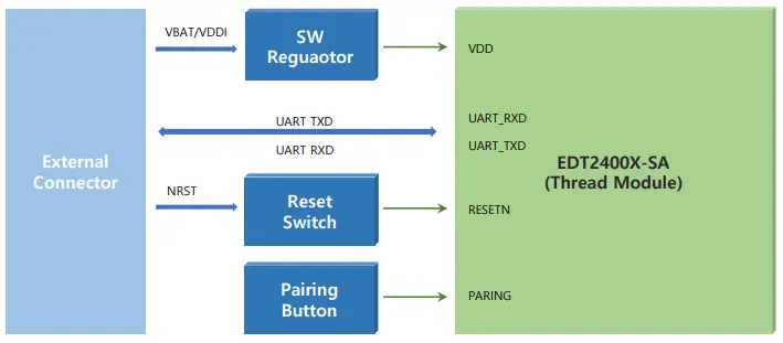
Operation Description
Vcc and Internal SW Regulator
Vcc input is input to the sw regulator. The SW Regulator generates a constant voltage (3.2V~3.4V) to supply power to MT-100C.
MT-100C Reset
When changing the input of NRST from High to Low, MT-100C is reset, and when changing the input from Low to High, MT-100C boots and runs the program.
MT-100C Paring
If the user wants to connect MT-100C newly to a matter Controller/Hub, press and hold the pairing button for more than 7 seconds. After 7 seconds, the mobile app can discover this device (MT-100C) via Thread , and the user can proceed pairing process.
External Connector Pin Map and Function Description
| PIN No | Pin Name | Signal Direction | Description |
| 1 | USR_TXD | Output | UART Transmission Signal |
| 2 | USR_RXD | Input | UART Receiving Signal |
| 3 | NC | No Connection | |
| 4 | GND | Power Ground | |
| 5 | VDDI | Power Input | Optional Power Input.
If the VBAT input is not used, it is an external constant voltage power input. |
| 6 | GND | Power Ground | |
| 7 | NRST | Input | Active low reset signal. |
| 8 | NC | No Connection | |
| 9 | NC | No Connection | |
| 10 | NC | No Connection | |
| 11 | NC | No Connection | |
| 12 | GND | Power Ground | |
| 13 | VDDI | Power Input | Same with PIN 5 |
| 14 | VBAT | Power Input | Battery Power is between 4.7~6.4V. |
| 15 | NC | No Connection | |
| 16 | NC | No Connection |
Operating Charateristics
Electrical Maximum Ratings
Note: Stresses exceeding Maximum Ratings may damage the device
| Parameter | Min | Max | Unit |
| VBAT(DC Power Input) | -0.3 | 12 | V |
| VDDI(Optional DC Power Input) | -0.3 | 3.8V | V |
| Current per I/O pin | – | 50 | mA |
Note: Current for all I/O pins is limited max 200mA
Electrical Recommended Operation Conditions
| Parameter | Min | Max | Unit |
| VBAT (DC Power Supply) | 4.7 | 6.4 | V |
| VIH (High-Level Input Voltage) | 1.71V | 3.8V | V |
| VIL (Low-Level Input Voltage) | 0V | 0.3V | V |
ESD Susceptibility
| Parameter | Min | Max | Unit |
| HBM (Human Body Model) | – | 2,000 | V |
| MM (Machine Mode) | – | 200 | V |
Communication Channel
| Channel | Frequency[MHz] | |
| 11 | 2405 | |
| 12 | 2410 | |
| 13 | 2415 | |
| 14 | 2420 | |
| 15 | 2425 | |
| 16 | 2430 | |
| 17 | 2435 | |
| 18 | 2440 | |
| 19 | 2445 | |
| 20 | 2450 | |
| 21 | 2455 | |
| 22 | 2460 | |
| 23 | 2465 | |
| 24 | 2470 | |
| 25 | 2475 | |
| 26 | 2480 |
FCC Information to User
This equipment has been tested and found to comply with the limits for a Class B digital device, under Part 15 of the FCC Rules. These limits are designed to provide reasonable protection against harmful interference in a residential installation. This equipment generates, uses and can radiate radio frequency energy and, if not installed and used under the instructions, may cause harmful interference to radio communications. However, there is no guarantee that interference will not occur in a particular installation. If this equipment does cause harmful interference to radio or television reception, which can be determined by turning the equipment off and on, the user is encouraged to try to correct the interference by one of the following measures:
- Reorient or relocate the receiving antenna.
- Increase the separation between the equipment and the receiver.
- Connect the equipment to an outlet on a circuit different from that to which the receiver is connected.
- Consult the dealer or an experienced radio/TV technician for help.
Caution
Modifications not expressly approved by the party responsible for compliance could void the user’s authority to operate the equipment.
FCC Compliance Information: This device complies with Part 15 of the FCC Rules. Operation is subject to the following two conditions: (1) This device may not cause harmful interference, and (2) this device must accept any interference received, including interference that may cause undesired operation.
RSS-GEN Section
This device complies with Industry Canada license-exempt RSS standard(s). Operation is subject to the following two conditions: (1) this device may not cause interference, and (2) this device must accept any interference, including interference that may cause undesired operation of the device.
Documents / Resources
 | MT-100C Thread Interface Module |
References
- User Manualmanual.tools