SOLIDYNE 542 APC Audio Processing Core FM and HD Audio

Specifications
- Product Name: SOLIDYNE 542APC Audio Processing Core
- Model Number: 542APC
- Input Connections: XLR, RJ45, AES-3
- Output Connections: MPX, FM antenna
- Control Interface: IP remote control, GPIO
- Web Interface: LAN and Internet access
Product Usage Instructions
Quick Installation Guide
Follow the quick installation guide provided in Section 1 of the manual for a basic setup of the SOLIDYNE 542APC.
Installation
Mounting
- Mount the device securely according to the instructions in Section 2.1 of the manual. Ensure proper ventilation.
Rear Panel
- Connect analog and digital audio sources as described in Sections 2.2.1 and 2.2.2 respectively.
MPX Outputs
- Utilize the MPX outputs for specific audio output requirements.
FM Antenna
- Connect the FM antenna to receive FM signals.
IP Remote Control
- Access the device remotely using the IP remote control feature detailed in Section 2.5 of the manual.
GPIO
- Learn about and utilize the GPIO connections for additional control functionality.
Updates and Upgrades
- Stay updated with the latest features by following the upgrade procedure in Section 2.7.
Settings
- Configure device settings including presets, password, and control methods as explained in Section 3 of the manual.
Overview
- Understand the overview of settings including presets and control options.
Frontal Panel Functions
- Learn about the functions available on the frontal panel for easy operation.
Web Interface
- Access the device settings and controls via the web interface from LAN or remotely over the Internet.
Status/Home Interface
- Monitor device status, presets, and audio inputs through the status/home interface.
FAQ
- Q: How do I update the firmware of the SOLIDYNE 542APC?
- A: To update the firmware, follow the procedure outlined in Section 2.7 of the user manual.
- Q: Can I control the device remotely?
- A: Yes, you can control the device remotely using the IP remote control feature detailed in Section 2.5 of the manual.
“`
About this manual
Manual Firmware
November 2024 5B 2.11
Solidyne® All rights reserved. No part of this manual may be reproduced, copied or transmitted in any form or by any means, electronic or mechanical, in whole or in part
Thank you for choosing us
Congratulations! The unit you now hold represents the pinnacle of digital audio technology. The 542APC processor is the flagship model in the Solidyne Broadcasting Processor series, encapsulating over 40 years of expertise in audio processing for broad casting.
The 542APC features a DSP-based audio processing core that operates advanced software, which defines the unit’s functionality and model.
Free software updates within the same model can be downloaded indefinitely, ensuring your processor remains up-to-date. Additionally, you can upgrade to more advanced applications that enhance performance, effectively providing the features of a new model–without requiring hardware changes.
The processor is fully controlled via a web interface. Simply connect the unit to a local network and enter the IP address displayed on the front panel into any web browser. This grants access to an intuitive Control Panel, optimized for touchscreens, for seamless operation. The IP-based access also enables remote control when the unit is installed at the transmission site.
For studio-based remote operation, the 542-RM controller offers a dedicated 7-inch touchscreen, allowing full control and real-time monitoring of transmission parameters.
Basic settings can also be configured directly from the front panel using the OLED display and control wheel.
The 542APC includes an integrated RDS encoder for transmitting text data to audiences, as well as an FM stereo encoder with dual MPX output.
Beyond its processing capabilities, the 542APC serves as a versatile monitoring and diagnostic tool. It incorporates an FM tuner and real-time signal analysis to evaluate critical transmission parameters, such as modulation depth, pilot tone level, and RDS performance, alongside audio quality metrics. The tuner is adjustable to any frequency, enabling monitoring of external radio stations as well.
Optional hardware expansion modules are available to extend functionality, including support for DANTE AoIP and streaming services (RTP, downstream, and Icecast/Shoutcast servers)
Whats in the box
1 Solidyne 542APC processor This user’s manual 1 power cord (Interlock) 1 telescopic antenna 1 micro-antenna (BNC terminal) 1 Guarantee card 4 Rubber feet
Please check that all these items are inside the box and that the equipment was not hit during the transfer.
Recommendations for the installing
Please read this manual carefully to get the best performance of the processor.
The Solidyne 542APC is designed to be installed in a standard 19″ rack. Its height is one rack unit.
Four self-adhesive rubber feet are included for the case where the unit is placed on a table.
When mounting the equipment in a rack, use flat head screws with a flexible washer (plastic or rubber). First tighten the lower screws and then the upper screws, to prevent the weight of the unit from pushing the upper angles. Do not tighten the screws too much, a slight force when tightening them is enough. Excessive force on the screws can deform or even break the panel angles.
WARNINGS
AC
Voltage
This unit works with 110/200 VAC.
The voltage selects from a switch located at rear panel.
CHECK THE VOLTAGE SELECTOR BEFORE PLUG TO THE AC OUTLET.
To reduce the risk of electric shock, do not remove the enclosure covers. Internal parts do not require user main-
tenance. Contact qualified technical assistance.
Connect the supplied 3-prong power cord to a 3 hole AC outlet. Do not use adapters. MAKE SURE YOU HAVE A PROPER GROUNDING.
The admiration mark within a triangle that appears in this manual alerts the user to the
presence of important operating and settings instructions.
The letter “i” within a circle in this manual alerts the user to the presence of important information, recommendations and advice.
Audio Processing Core – SOLIDYNE 542APC
Page 5
Page 6
Audio Processing Core – SOLIDYNE 542APC
Section 1
Quick installation guide
POWER SOURCE AND TURN ON
CONTROL
Before plugging the unit to the AC line, check if the 110/240V VOLTAGE SELECTOR is in the correct position. Use the supplied three-prong Interlok cable and ensure proper grounding.
The unit has an on/off switch on the rear panel.
Some basic functions can be set from the rack’s frontal panel. The operation is intuitive: Turn the jog wheel to choose options or change values. Push the jog wheel to access options or to confirm a value.
ETHERNET CONNECTION All functions and settings of the 542APC are controlled from an internal WEB interface. Connect the 542 ACP’s ETHERNET port to the LAN router, using a standard UTP cable. By default the unit works in DHCP mode. The router will assign it an IP address, which is displayed on the OLED screen of the processor.
WEB CONTROL Using any network terminal, enter the IP address in a WEB browser. The browser will display the 542’s internal WEB pages. The initial screen is a Status page. To change set and edit options, press the ADJUST MODE button located at the top right. Read this manual for details.
INPUTS
CONNECTION Default active input is the balanced analogue with XLR connection. There is a second analog in put on RJ45 (StudioHub(c) compatible) and digital inputs AES3 and IP streaming (optional). To switch the input proceed as follows.
SET UP The analog inputs are set to operate at -18 dBfs with +4dBu nominal input level. When the mixing console peaks are 0VU, signal peaks at the 542APC input should be between -22 and -9 dBfs. The input gain can be adjusted as shown below.
INPUT SELECTION (from the frontal panel) Turn the jog wheel until see the INPUT screen. Press the navigation wheel to access to the “active input” configuration. Turn the wheel to select an input (number and name of the input are shown eg “2: ANALOG2”). Press the wheel to confirm the selection. The current active input is signalized by an arrow (input levels screen).
CHANGE THE INPUT GAIN (from the frontal panel) Turn the wheel until see the “enter SETUP MENU” screen. Press the wheel to enter. Turn the wheel to select “IN” and press to enter SETUP of inputs. Press the wheel to select “INPUT SEL”. Turn the wheel to select the desired input. Press to confirm. Select “GAIN” by turning the wheel and press to activate the gain change. Turn the wheel clockwise to increase the gain and counterclockwise to decrease it. Adjust the gain so that the indicators show a peak value between -22 and -9 dBFS. Press the wheel to confirm the gain. Turn the wheel to select BACK and exit this menu. Turn the wheel to the last “BACK” icon to exit the SETUP menu. Changes are saved.
Audio Processing Core – SOLIDYNE 542APC
Page 7
Page 8
OUTPUTS
MPX The stereo encoder has dual MPX output with independent level adjustment. Connect an MPX output to the transmitter using 50 or 75 Ohm coaxial cable. AUDIO 542 APC has two balanced analog stereo outputs: XLR and RJ45. Both outputs gives the same audio signal. From the WEB Panel, the de-emphasis curve (50/75uS) can be enabled/disabled for each output (for WEB-casting or link with repeaters).
MODULATION INDEX
To adjust the modulation index, 542APC has: · Built-in FM tuner · Modulation meter · Reference tones generator
RECEPTION ANTENNA The broadcast of the station (or any other FM station) can be tuned into the 542, to monitor in real time the modulation index and other measurements. Connect the supplied telescopic antenna to the FM ANT (BNC) connector on the rear panel. Two receiving antennas are included from the factory: a telescopic antenna and a fixed micro-an tenna. Usually the telescopic antenna is suitable for reception at the transmitting plant. For more details on reception and antennas, see 2.4 – FM receiving antenna.
CALIBRATION TONES Using a computer on the same LAN that the 542APC, run a WEB browser (preferred Google Chrome) and enter the IP showed in the display to access to the 542’s WEB pages.
Switch to SETUP view.
Go to the left menu at and click on FM Output (MPX).
Turn on the CALIBRATOR. The input signal will be replaced by a sinusoidal tone. By default, the pilot tone is set at 9% and RDS modulation is 4%.
SET THE MODULATION INDEX
From the WEB pages interface, access to the FM tuner/analyzer by clicking the option on the left menu.
Set the FM dial to receive the transmission. Check the modulation depth on the FM MODULATION MONITOR.
The measurements are valid only when the indicator RxQTY reports GOOD. If the reception is poor, check and adjust the orientation of the antenna, or change the antenna by other type.
Change the MPX gain of the transmitter until achieve the desired modulation index on the 542’s modulation meter (usually 100%). The default level for MPX output is 5 VPP. For fine tuning, change the MPX output level
Turn off the calibrator. The program signal is reestablished. Audio peaks will modulate exactly at the level set with the calibrator.
Audio Processing Core – SOLIDYNE 542APC
THE SOUND
The radio station is on the air with the sound of the Solidyne 542APC. Now you can listen to the different sound presets to find the sound that fits the needs of the radio. Tune into a good audio system (or use good headphones). Or use the 542’s internal tuner. Proceed as described be low.
From the front panel, turn the navigation wheel until the PROCESS screen is displayed. The current preset is displayed on the bottom line of the screen.
Press the control wheel to change the preset. Turn the wheel to choose a preset and press again to confirm. The sound in the air will
gradually change to the new setting. From the WEB Control interface, the current preset is changed from the PRESETS sec –
tion located in the fixed monitoring area.
562APC has 16 only-read factory presets and 16 user’s presets. The user can create new presets starting from factory presets. All this actions are available in the WEB interface.
SOUND WIZARD The WIZARD allows to the user to customize a factory preset with few controls and without ad vanced knowledge. Four sliders changes the sound profile of a factory preset, reinforcing or softening the following aspects:
· Bright · Bass · Compression/Density · Loudness
WIZARD also allows to enable/disable and change the intensity of the ENHANCERS stages: · Parametric EQ · Bass enhancer · Stereo enhancer
Remote technical assistance
Once the equipment is installed, the Solidyne’s Technical Assistance team can remotely access the processor to make final adjustments and measurements, if necessary.
For this, follow this steps:
1. The 542APC processor must be connected to the LAN using the port Ethernet for remote control (see ref.11 in Figure 1).
2. The processor must have the reception antenna installed. For details about the receiver and the antenna please refer to 2.4 FM Antenna.
3. Check the access to the processor. Using a computer connected to the same LAN, run a web browser and enter the IP address showed in the OLED display.
4. Using the same computer, download the software TeamViewer QuickSupport: https://get.teamviewer.com/solidynequick
5. Run the downloaded file TeamViewerQS.exe. The computer will connect with the Solidyne’s Technical Assistance team, who will be able to take control of the computer to access the processor. The “Allow remote control” window is displayed on the screen, including a chat with the Support team.
In order to coordinate the assistance, please contact to: · soporte@solidyne.ar · Whatsapp +54 9 11 3119-3254
Audio Processing Core – SOLIDYNE 542APC
Page 9
EMPTY PAGE
Page 10
Audio Processing Core – SOLIDYNE 542APC
Section 2
Installation
2.1 Mounting
The unit can be mounted in a standard 19 “rack or on a table. In the latter case it is advisable to place the rubber feet in the base of the processor. Do not place the unit on an unstable surface or shelf; The unit may fall, causing injury to persons and damage to the unit.
The ambient temperature should be between 5ºC and 40ºC. Avoid direct sunlight on the processor or the proximity of heat sources.
The openings and grooves allow ventilation and air circulation. These openings must not be blocked or covered, so as not to interfere with the cooling of the internal components of the equipment.
The 542APC has internal protection against RF fields, which allows them to be mounted close to transmitters (AM or FM). Avoid the presence of strong electromagnetic fields (power transformers, motors, etc.).
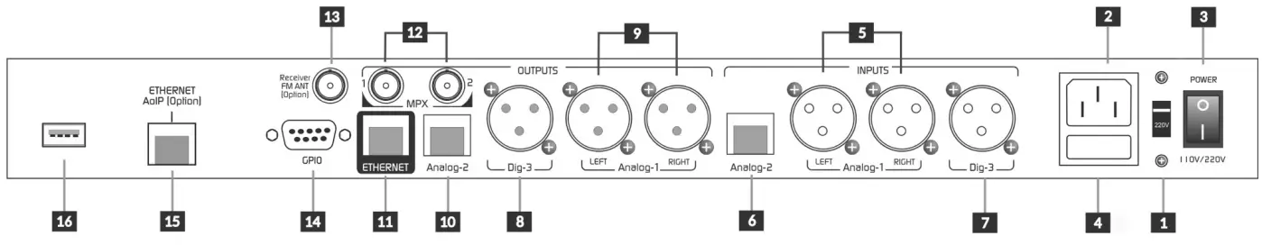
2.2 REAR PANEL
2.1.1 Power supply
Before connecting the unit to the AC power supply, ensure that the position of the AC VOLTAGE switch – -3- – matches the mains electrical voltage:
200/240V or 100/130V
The unit is switched on by a main switch -3-. The mains voltage must be kept within a range of less than 10%. Otherwise use fast acting voltage stabilizers (ferroresonance or electronic). The unit has a general fuse -4 of 1A.
Do not mix the power cord with the audio cables, especially with those that carry analog audio.
Do not use adapters that will void the power cord ground -2- Remember that the entire audio system must have a secure grounding. It is recommended to follow the current regulations (Article 810 of the National Electricity Code (NEC) -USA- ANSI / NFPA No. 70-1984). These provide information for proper grounding.
Figure 1- Rear Panel
2.2.1 Analog audio connections
2.2.1.1 XLR inputs and outputs
542APC has one balanced stereo input -5 and one balanced stereo output -9- using XLR. The inputs are electronically balanced. The analog XLR connects as is standard:
Balanced XLR 1 = GND 2 = Balancead signal (+) 3 = Balanced signal (-)
Unbalanced XLR Inputs: Live = 2
GND = Joint 1 and 3 Outputs: Live (+) to pin 2; leave pin 3 unconnected.
GND = pin 1
Take special care to keep the phase in balanced wiring.
Use two pair shielded cable, preferably with double shielding. It is recommended to keep the length less than 30 meters, although in special cases can reach 100 meters accepting a reduced loss at high frequencies.
2.2.1.2 RJ45 inputs and outputs
With the advent of audio over IP (AoIP) various manufacturers adopt RJ45 connectors and shielded twisted pair cable to replace traditional audio connectors. A single RJ45 connector contains two balanced lines, reducing the number of connectors and the number of connectors. In addition, the use of structured cable facilitates installation due to the availability of components and tools used in data networks, avoiding welding.
At the end of the STP cable the connection to the audio device still requires standard audio connectors. Solidyne provides several adapter patch cords short with male or female RJ-45 at one end and the necessary audio connector at the other end.
Audio Processing Core – SOLIDYNE 542APC
Page 11
All RJ45 audio connections are compatible with the StudioHub cables (http://www.studiohub.com/).
The balanced inputs 6 and unbalanced outputs 10 over RJ45 connects using shielded twisted pair (STP) CAT5. The following table shows the signal distribution of RJ45 connector.
RJ-45
RJ45 PINOUT
PIN CABLE COLOR
1
Orange/White
2
Orange
3
Green/White
4
Blue
5
Blue/White
6
Green
7
Brown/White
8
Brown
Table 1 RJ45
RJ45 BALANCED INPUT
PIN
CABLE COLOR
1 Left channel (+) 2 Left channel (-) 3 Right channel (+) 4 GND 5 Reserved 6 Right channel (-) 7 -15 (optional) 8 +15 (optional)
Orange/White Orange Green/White Blue Blue/White Green Brown/White Brown
Table 2 RJ45 balanced inputs
RJ45 UNBALANCED OUTPUTS
PIN
COLOR DE CABLE
1 Left channel (+) 2 GND 3 Right channel (+) 4 GND 5 Reserved 6 GND 7 -15 (option) 8 +15 (option)
Orange/White Orange Green/White Blue Blue/White Green Brown/White Brown
Table 3 RJ45 unbalanced outputs
2.2.2 Digital audio connections
2.2.2.1 AES-3
The processor includes an AES-3 input and output. When using the digital input, it is also convenient to connect the analog inputs. If the signal is lost at the main input, the processor automatically switches to another input that has a signal. The default entry is selected from the “Inputs” menu, as explained below.
S/PDIF: A S/PDIF signal can be connected to AES-3 by using an S/PDIF-to-AES3 adapter. The figure shows a compact adapter with XLR and BNC connectors.
The AES-3 output is balanced, using a male XLR. The connections are the following:
XLR
Signal
1
GND
2
AES3 (1)
3
AES3 (2)
Table 4 Standard AES-3 connection
2.2.2.2 Incoming streaming port (optional)
The port “Ethernet AoIP” -11 allows receiving an incoming digital audio streaming, used for transporting audio from Studios to Transmitting Plant. See “2.8 – AoIP Connection”. RTP and Shoutcast/Icecast servers are supported.
From Studios, the RTP streaming can be encoded using mixing consoles Solidyne DX816, series 2600, series UNIDEX or the Solidyne ADA102 link. Equipment of others brands also can be used. For details please see “SECCTION 5 Models with the optional AoIP”
2.3 MPX outputs
The 542APC features dual MPX output -12 , with independent level adjustment.
The output connectors are BNC type. 75-ohm coaxial cable (RG59 standard on CCTV) can be used for the connection. The length of this cable should be kept less than 25 meters.
When entering the transmitter via MPX, make sure that the internal pre-emphasis network of the transmitter is switched off (flat response 20 – 100 kHz). The pre-emphasis on 542APC is fixed at 50 or 75 microseconds.
It is very important to have a good design of ground connections. In case of doubt, contact Solidyne describing the equipment and the connection diagram used.
2.4 FM antenna
The internal receiver allows you to tune the transmission of any station and view the modulation level, audio levels, RDS data and other transmission issues (see “3.9 FM analyzer monitor”).
The BNC connector labeled “Receiver FM ant” -13 provides connection to the antenna of the internal FM receiver. From factory two antennas are provided:
· Telescopic mini-antenna: Is used for the most of situations.
· BNC micro-antenna: When the RF field intensity is too high, the gain of telescopic antenna can cause the saturation of the receiver. The indicator RF LVL (FM Monitor Analyzer) is stuck at the maximum value 100 dBuV. In this case, use the BNCterminal.
Depending on the installing conditions (location of the equipment, distance to the transmitting plant, etc.), a wired antenna (not supplied) installed outside the building may be necessary.
Page 12
Audio Processing Core – SOLIDYNE 542APC
2.5 IP remote control
The ETHERNET port -11 allows the connection of the 542APC to a LAN to access the WEB Control Panel. The network router assigns an IP address to the processor (DHCP). This IP allows access to the internal web pages of the processor, using a computer connected to the same LAN and a WEB browser (Google Chrome is recommended).
For details on use see “3.4 Remote control via web”.
2.5.1 Internet remote access
To access a device outside the local network, there are two methods:
If the device is directly connected to the Internet, enter the IP address provided by your ISP.
If the device is connected to another LAN (with internet access): configure the LAN router in order to redirect the incoming packets on port 80 to the local IP address assigned to the 542APC, and to redirect packets using port 9762 (or other port assigned to RDS).
WARNING AVOID TO RUN FIRMWARE UPDATES WHEN ACCESS TO THE DEVICE IS VIA INTERNET. TO UPDATE FIRMWARE REMOTELY, USE A SAFE POINT-TO-POINT CONNECTION (VPN).
2.6 GPIO
The Solidyne 542 has one General Purpose Input and one General Purpose Output (GPIO, see Figure-1, -14 ) using a female DB9 connector. The pin-out is the following:
PIN
SIGNAL
1 GPI – VOLTAGE
2 GPI COMMON REF
3 NOT CONNECTED
4 GPO OPEN COLLECTOR
5 12 VDC / 100 mA MAX
6 a 9 CHASSIS GND
2.6.1 GPI connection and use
The General-Purpose Input (GPI) allows for switching the processing setting to a voice-optimized preset when microphones are activated on-air.
The GPI is triggered by applying a voltage between 5 and 15 volts to PIN-1. It does not use an internal ground reference. PIN-2 is connected as GPI-COM to the external signal. This setup prevents feedback loops that could generate noise. GPI is non-polarized, meaning it can be activated with either positive or negative voltages within the operating range.
When the voltage is zero, the system reverts to the main processing preset. The switching between processing presets is confirmed on the equipment’s OLED display.
When the Solidyne 542APC is installed in the studios, GPI triggering can be accomplished by directly connecting the “on-air” light voltage output to the GPI of the 542APC. Ensure that the “tally light” voltage provided by the console is within the supported range (5-15 VDC).
When the Solidyne 542APC is at the transmitter site, GPI triggering can be achieved using a remote contact (relay) from the Studio-to-Transmitter Link (STL) if the equipment provides this feature.
2.6.3 GPO connection and use
The General-Purpose Output (GPO) allows controlling an external device based on a specific condition of the processor.
It connects to PIN 4 of the DB9. The GPO is a “Normally-Open” dry contact (open collector) contact closes (connects to chassis ground) when active. It supports a maximum of 100 mA.
The conditions that trigger the GPO are configured in the web control interface under the CONFIGURATION section. Refer to section 3.11.1 GPIO CONFIG for more details.
2.7 Updates and upgrades
The 542APC is an Audio Processing Core on which runs an audio processing application (firmware) that defines the characteristics of the unit (model). By changing the software, the user can change the characteristics of the processor.
The successive updates of the processor software can:
Optimize the processing stages Add new processes and functions. Improve or modify the graphical user interface. Add new processing settings (presets)
The current version and model are displayed on the OLED display starting screen; and on top line of the WEB pages.
The update can be done on-the-air. It could cause a brief audio drop of 2 seconds aprox.
2.71 Procedure
VERSIONS PRIOR TO 2.0
For units with firmware 1.35 or older, the update procedure is different. Please refers to the corresponding user manual available older manuals section at www.solidyne.ar
To update the software version proceed as follows:
1. The computer that access the 542APC must have Internet access. The computer and the processor must be connected to the same network.
2. Enter the 542’s CONTROL IP address in a web browser (Google Chrome recommended) to access to 542’s REMOTE CONTROL web pages.
Please refers to 3.4 WEB interface to know how to access the web pages.
Audio Processing Core – SOLIDYNE 542APC
Page 13
3. Enable the advanced mode by clicking on SETUP option at the upper right-corner of the main page. The main menu will appear. From there, select the item INFO.
4. On this webpage, the software will search online for available updates. If new firmware is found, a download link will appear.
5. Download the new firmware from the link. 6. On the section SOFTWARE, clic on the “Discov-
ery and Update” item. This will download a Windows application required to install the firmware. 7. Extract the downloaded file and install the application. The Installer will create a folder named “Solidyne Audio Processor” in the Windows Start menu. Optionally the installer can create a desktop shortcut. 8. Run the app Discovery and Update.
Figure 2: Update tool
9. Click the “Discover…” button. A list will appear displaying the Solidyne hardware connected to the network.
10. Select the 542APC device and click the “Update firmware” button.
11. In the popup window browse the for downloaded firmware file and click “OK”. The internal software of the 542APC will be overwritten.
12. The processor will remain on-air during the update, with a brief interruption (less than 2 seconds) when it reboots.
WARNING DO NOT turn off or disconnect the processor from the LAN during this operation. It can cause damage non reparable by the user.
WARNING AVOID TO UPDATE THE FIRMWARE USING WI-FI NETWORKS.
REMOTE CONNECTION DO NOT UPDATE REMOTELY IF THE 542APC is connected directly to Internet (PORT FORWARDING). Use any remote desktop software (pcAnywere, TeamViewer) to access to a network terminal and from the local computer, run a web browser to access to the 542APC.
Page 14
Audio Processing Core – SOLIDYNE 542APC
Section 3
Settings
3.1 OVERVIEW
All basic settings can be set from the frontal panel. For advanced settings and to customize the sound, the unit must be connected to a local network via the ETHERNET port, in order to access to the Web Control interface using a WEB browser (Google Chrome is recommended).
3.1.1 Presets
The presets store the settings of all AUDIO PROCESSING stages, which define the sound profile of the station.
542APC has 16 factory presets and 16 user’s presets. Presets from 01 to 15 are only-read factory settings, made to cover different sound criteria and broadcasting needs. Each of them has a name that describes its goal (Voice Loud, MaxBass, Maxludness, etc.).
The user can customize a factory preset by copying it on a user memory and editing using the simplified “Wizard” controls, or the advanced controls of each processing stage.
System settings, like input levels, MPX level, RDS, etc., are not stored into the audio presets, since they are global and independent of the current preset.
3.1.2 Password
Using the WEB interface, the user can assign an access password of up to 8 characters (letters, numbers and signs) to prevent the access to unauthorized users.
By default the password is disabled (auto-login mode). If enabled, default password is 1234.
For details, please refers to 3.11 System settings
3.1.3 Ways of control
The 542APC can be controlled in several ways:
a) The essentials can be adjusted directly from the front panel of the rack.
b) Connecting it to a local network, the Web Control Panel are accessible from a computer by entering the processor’s IP address in a web browser.
c) Lite Commander: It is an application that runs on a computer and accesses the 542APC (via Ethernet) to change the current sound preset or switch the transmission mode (mono/stereo). Changes can be scheduled (see “3.5 Lite Commander”).
3.2 FRONTAL PANEL FUNCTIONS
The basic settings can be done on the hardware rack. Advanced settings and the audio processing stages are available only from the 542’s remote WEB interface. The front of the unit has an OLED display and a rotary wheel with push-button.
Turn the wheel to choose options. Push the wheel to enter or edit an option. Push the wheel again to confirm a value. Turn again to select another option, or push on
“BACK” to return to the previous screen.
3.2.1 Start up and lock screens
When the 542APC turns on, the OLED display shows the star up screen for a few seconds (it reports the firmware version). After starting, the display will show the current IP address, the MAC, and the name of the current preset.
Figure 3: Start up
1. Push on the wheel to change the current preset. 2. Turn the wheel to navigate the presets (16 only-
read and 16 user’s presets). 3. To confirm a preset, push the wheel. The sound
on-the-air will change.
The lock screen allows to enable/disable password access. When the hardware is locked, screens can be navigated but options cannot be accessed.
To lock the access, go to LOCK/UNLOCK screen and push the jog wheel to LOCK.
To unlock, push on LOCK/UNLOCK again. Password will be required (default: 1234).
Figure 4: LOCK/UNLOCK screen
Audio Processing Core – SOLIDYNE 542APC
Page 15
3.2.1 INPUT STATUS
The screen INPUT shows the signal level on each audio input. The active input is indicated by an ARROW next to the number. By default the active input is the analogue XLR.
3.2.4 Headphones
It adjusts the level for the headphone output. The user can choose the audio source between the following signals:
· Audio input. · FM tuner. · AGC output. · Audio processed (de-emphasized).
Figure 5: Inputs
3.2.1.1 INPUT SELECTION (from the frontal panel)
Turn the wheel until see the screen INPUT. Press the wheel to change the current active input. Turn the wheel to select an input (number and name
of the input is shown at right eg: “2: ANALOG2”). Press the wheel to confirm an option. The new active input is indicated by an arrow next to
the number. The last step is the gain adjustment, explained later
in the SETUP screen.
3.2.2 OUTPUT STATUS
Figure 8: Headphones level
· To choose an audio source, push the wheel and rotate to navigate the options. Push again to confirm.
· To leave the screen HEADPHONES, press and hold the wheel until see a menu with alternating options. Release the wheel on BACK to return, or SETUP to go to SETUP screen.
3.2.5 SETUP
To access to settings options, press the wheel on the screen SETUP MENU:
Figure 9: Setup input gain
Figure 6: Outputs
Shows the audio level at each output. From the frontal panel, the output settings are in the SETUP screen. The procedure to change the output gain is like the explained above for the inputs.
3.2.3 PROCESSING MONITOR
Figure 7: Processing
It shows the action of the AGC, multiband AGC, the multiband compressor, multiband limiter, clipers, wideband limiter and final clipper. The audio processing settings can be edited only accessing with an external computer to the 542’s web interface.
Figure 10: Settings
The basic settings are:
3.2.1.2 INPUT GAIN
The inputs gain is set on thescreen SETUP INPUT CONFIG. Gain control works in a range of +/- 14dB. The gain for the analog inputs is refered to -18dBfs for nominal input level of +4dBu (AES K18). It represents a headroom of 18dB.
To adjust the level, the on-air mixing console must peaking at 0VU with audio program (i.e. music). Set the input gain in order to the peaks in the level meter of the 542APC moves between -22 and -9 dBfs.
Turn the jog wheel until see the screen “enter SETUP MENU” and push the wheel to enter.
Turn the wheel to select “IN” and press it to access to INPUT CONFIG.
Press the wheel to select “INPUT SEL”. Turn the wheel until see the desired input and press to confirm.
Page 16
Audio Processing Core – SOLIDYNE 542APC
Select “GAIN” by turning the wheel and press to edit the gain value.
Turn the wheel clockwise to increase the gain and counterclockwise to decrease it. As was explained above, the gain adjusts so that the level indicators peaking moves between -22 and -9 dBFS.
Press the wheel to confirm the gain.
Turn the wheel to select BACK and press to exit.
Turn the wheel to the last “BACK” icon to leave the SETUP menu. Changes are saved automatically.
INPUTS: Set the current active input and the inputs gain.
OUTPUTS: Set the level for the audio outputs.
STEREO GENERATOR
Set the level for the pilot tone; the moduation index for RDS sub-carrier and the levels for MPX-1 and MPX-2 (in volts peak to peak).
Figura 11: Stereo Coder
FM RECEIVER
Allows to set the FM band type and tuned frequency.
Figure 12: FM Mode and tune
ETHERNET
Figure 13: Ethernet
Allows connection to a LAN to access the internal WEB screens. By default, the device comes in DHCP mode. The home screen displays the current IP address.
3.2.4 FM RECEIVER
The internal FM receiver allows to tune in a FM station and analyze the main transmission aspects. There are three screens that display transmission data: FM MONITOR, FM MODULATION MONITOR and RDS ANALYZER.
Figure 14: FM receiver
3.3 Processing Presets
The presets store all the values and settings of the sound processing stages, which defines the sound on the air.
The factory presets was created to meet different needs of broadcasters. Some presets focus on sound quality, others ones prioritize the loudness, the bass-boost, treble enhancement, or the intelligibility of voice. Presets from 01 to 03 are made for voices. Presets from 04 to 13 are for general purpose and are sorted by their loudness level, from lowest to highest.
The user can copy and edit a factory preset to create their own preset, as will be explained below.
When choosing and adjusting the audio processing presets, keep in mind if it is a single program for the whole day; or whether the automatic switching by microphone is activated, or by hourly range. In the first case, a commitment adjustment must be used compatible with all types of voices and music that the station handles. Automatic switching of presets eliminates compromises as each preset will be optimal for that type of music or voice. This also reduces the auditory fatigue associated with radio stations that use rigid processors, without computed control.
At next: the concept behind the presets. We recommend to rear carefully the following notes.
3.3.1 VOICE PRESETS
The VOICE presets are set to process the voices. When the microphones go on-air, the 542APC can switch the preset to process the audio with a preset designed for the voices (see 3.11.1 Input action).
The main difference of adjustments for the voice, regarding the adjustments made for the music are the times of attack and recovery times of the AGC and compressors and the wide-band limiter.
The wide-band AGC must recover its gain fast enough to compensate, for example, a low-level telephone communication. This is achieved with the quick window settings, as if the overall WB AGC times are very fast it will cause constant and audible level fluctuations.
The hold threshold is set to values between 6 to 8 dB higher than the values used for music, to avoid constant level changes. To make this preset, we use program signal containing a mix of announcers and promotional cuts and ads.
The attack of the WB AGC must also be fast, but a very fast time will cause audible level changes because of screams or laughter that can occur in front of the microphone in some types of shows. The action of the AGC must go unnoticed.
The multiband AGC should not have a very wide correction range. Between 2 and 3 dB is sufficient for most purposes. The coupling between bands should not be greater than 3 dB to avoid imbalances in the spectrum, except for the bass band that tolerates differences of 4 to 5 dB. This is sometimes convenient as it helps to balance the presence of bass between different voices. Remember that you can use the MB AGC Dynamic EQ to define an equalization profile.
Audio Processing Core – SOLIDYNE 542APC
Page 17
The attack times of the compressors must be fast, mainly in the LOW band, to contain the great impulses that take place in the attacks of the word, when the compressors begin to work. If the attack times are slow, excessive limitation and clipping of the signal may occur at certain speaker words, and the announcer will sound “saturated” or “dirty” for a brief moment, when he start to speak (and after each pause greater than the recovery time).
The recovery times are more flexible, so they adjust according to the type of sound that the station desire.
As a general rule, slow recovery times will produce a “soft” and natural sound, while fast recovery times will increase the loudness, but processing becomes more aggressive (greater compression/limitation) and the voices sounds harsh.
Respect to the control Drive on the limmiters, the voices do not resist too much multiband compression. An excessive processing will sound unpleasant to the ear and will detract from the naturalness of the voices.
TAKE IN MIND
· When creating customized preset for the voices, be aware that the equalization should not be too far from the preset used for music. It is recommended that the density equalizer in the preset for voices maintain a similar equalization profile that the used in the preset for the music.
· When using GPI switching, we recommend customizing the settings used for voice and music so that the SUPER BASS and STEREO ENHANCER stages remain in the same state in both programs. Stereo Enhancer processing will have no effect on the voices, since they are monaural (the same signal on both channels) but will affect the background music.
3.3.2 SOFT PROCESSING
This is the softest preset for music. It is an adjustment of great dynamics and less loudness. It seeks to respect the balance of the orchestra, maintaining the dynamic expression, within the limitations of FM transmission.
The THRESHOLD of the multi-band compressor are adjusted to produce less compression. The Density EQ works with values in the order of -4dB, resulting in a higher dynamic range but reducing the loudness. Excessive multiband compression can cause a spectral imbalance that is very audible in acoustic instrumentation (jazz and folk) and orchestras. Because of the characteristics of these musical genres, a good ear will judge as excessive the audio processing that would be appropriate for rock, pop and mainstream music.
The times for MID-2, Presence and HI require special attention, thinking in the soloist instruments. The recovery times of the bands must be similar, otherwise modulations of the timbre in some instruments may occur.
The adjustment strengthens the bass slightly. The bass dynamic is maintained with ½ second recovery time for the LOW band.
High frequencies are not emphasized. It seeks to prioritize the warmth, “sharpness” and definition of the instruments over the “bright effect”. For this reason the recovery time of treble band (HI) is sightly slow. Keep in mind that the listeners can always emphasize the treble on their tuners (and usually they does!).
Regarding the announcers, this preset will not achieve high impact voices, with “fat” basses, because it works
with little multiband compression. It is recommended to use GPI switching and use the Voice-Soft preset for voices.
3.3.3 DeepBass/XtendedBass
Both settings emphasize bass. DeepBass reinforces very low frequency present in the original material, at frequencies around 96 Hz, and maintains the “punch” by releasing the compression threshold of the LOW band and adjusting the limiter/clipper of that band to almost 100% (0.25dB). XtendedBass uses the “SuperBass” stage to extend and reinforce low frequencies in the mid-bass zone (100 – 300 Hz).
While the first adjustment reinforces low-performing speakers with good low-frequency response, the second is appropriate to force the presence of bass on systems with small, limited-response speakers.
3.3.4 Vocal Music
These settings are created with music in which the singer predominates in the foreground. To create the preset were used orchestrated pieces and music with rhythmic bases. The goal was to keep the vocal range “soft” to get “clean” and defined vocals.
The AGC MB has its range of action very limited, to avoid colorations and sudden changes of level due to the great dynamics that many of the songs with predominance of the singer have.
Compressor recovery times are a key setting. When they are very fast, the voices can sound “harsh”.
3.3.5 MaxLoudness
This presets provides the loudest sound. They are focused on the loudness. In presets with high loudness, the spectral balance can be altered, because frequencies of the average range are emphasized.
The dynamics are strongly reduced to achieve high levels of average energy. MaxLoudness 1/2/3 presets are for general pourpose, as they respond well with different music styles. They use different clipping level for MPX (overdrive).
MaxLoudness-3 was created with pop hits of the last decade, that have strong presence of electronic rhythmic bases and synthesizers, and very high levels of loudness according to the criteria used in the mastering process.
The combination of hard compression with high gain results in a compact sound, which may sound “harsh” on the aire. Many FM stations that prioritize a high loudness are especially looking for this kind of sound.
3.3.6 Presets optimized for ITU BS.412
Presets “BS412 Hi End” and “BS412 Punch” are optimized to be used with the MPX ITU BS.412 power control.
The broadcasters regulated by BS.412 are free to use any of the factory presets, but the optimized presets make better use of the dynamic range that is generated by the relationship between bounded MPX power and 100% modulation.
Page 18
Audio Processing Core – SOLIDYNE 542APC
3.4 WEB INTERFACE
3.4.1 Accessing from the LAN
All setup options, advanced settings and audio settings are accessed using an external computer.
1. Connect the 542APC CONTROL Ethernet port to the LAN router/switch. DO NOT CONFUSE THE CONTROL ETHERNET PORT WITH THE STREAMING ETHERNET PORT (units with the expansion STREAMER /AoIP).
2. The processor will acquire an IP address via DHCP, which will be displayed on the OLED screen located on the front of the rack. SOLIDYNE MULTI-DISCOVERY When the unit is not withing view, the user can obtain the IP address using the ‘Solidyne Multi-Discovery’ application on a Windows computer. This tool can be downloaded from the following link: https://www.solidynepro.com/DW/IP.exe.
3. Open the PROTOCOL drop-down menu, select SOLIDYNE and click the DISCOVER button to locate the device.
4. Double-clicking on the listed item to directly open the WEB Control interface in the default browser.
5. Alternatively, the user can manually enter the IP address into a web browser (recommended: Google Chrome) on a computer connected to the same LAN as the 542APC.
3.4.2 Remote access via Internet
In units equipped with the STREAMER AoIP expansion (only devices with serial number AD and later), remote access to the processor is simplified through a service that generates a fixed link, eliminating the need to work with static IP addresses and port forwarding. For details, please refer to Section 5 Devices with AoIP services
Monitoring area
If the device does not have the simplified service, remote access outside the LAN can be done in two ways:
· A simple method that requires no additional configurations is to use remote desktop software (TeamViewer, pcAnywhere, Windows Remote Desktop, etc.) to access a computer within the LAN, preferably connected via Ethernet cable. By remotely accessing that computer, a web browser (recommended Google Chrome) is run, and the web interface of the 542APC is accessed. This allows for remote control of the processor and even firmware updates without risks, as the communication between the remote computer and the 542APC processor occurs within the local network. The internet only plays a role in controlling the remote computer.
· The second option requires knowledge of network configuration and access to the local network setup. The details of these configurations are beyond the scope of this manual. The process involves installing the processor with a static IP address and configuring the local network to allow external access to that IP address. This requires advanced port forwarding configurations, contracting static public IPs, and/or using DNS server services. Consult a qualified network administrator for assistance.
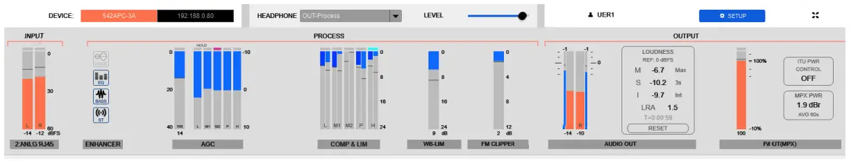
3.5 Status/home interface
The home screen is a monitoring panel that shows the status and the action of all processor stages. It is subdivided into sections that can be expanded or collapsed by pressing the ± icon. In this way, the user organizes the monitoring screen at their convenience.
Figure 15 – Expand/collapse sections
NOTE From this point onward, many screenshots are displayed with
inverted colors to optimize printing this manual on paper.
Audio Processing Core – SOLIDYNE 542APC
Page 19
The upper zone is fixed and remains visible in all screen modes, both in the MONITORING screen and in the SETUP screen.
It contents the following indicators: · Signal level on the active input (RMS and peak in dBFS)
· Processing meters: status of the Enhancers (on/ off); AGC (dB); reduction gain meters for compressors and limiters (dB); clippers action (active/inactive); wide-band limiter (dB) and MPX clipper (dB).
· Level on the audio outputs: A double-meter shows peak and RMS value. The Loudness Meter shows the audio level according the EBU-R128 norms.
The upper row shows: · The IP address.
· The signal source and the level for the HEADPHONES (the web control remember the level assigned to each source).
· The USER; to enter to the screen SETUP when the password is enabled.
· A button to switch to SETUP screen.
The status view does not allow to edit settings or change the processing. To be able to edit the configuration, enter to the mode SETUP (with the button located in the upper right corner of the window).
Preset and Sound Wizard
This section shows the current preset and simplified Wizard controls; that allow the user to quickly customize the character of the sound.
The user can change the current preset; edit the user presets with the Wizard controls and access the creation of new presets.
The CLICK HERE TO EDIT option accesses SETUP mode to save changes or create presets.
FM receiver Monitor Analyzer
Shows the most relevant parameters of FM transmission analysis. The receiver configuration and advanced reports are obtained in the SETUP mode, in the FM Receiver menu option (see below).
Audio Inputs and Outputs
This section displays the level indicators for the audio inputs and outputs, and for the MPX1 and MPX2 composite outputs.
Time Graph
It displays a graph that shows the evolution of the modulation over time. The display can be switched between:
MPX level modulation measured by the internal FM tuner MPX ITU BS412 power
3.4.3 SETUP mode
The SETUP mode allows the user to edit the parameters of the 542APC. The access to this mode can be restricted by password. In the SETUP screen, a slide-menu is enabled on the left of the screen, which contains all the instances and options of the processor.
WARNING: Always press SAVE after change a value in a processing stage. The button SAVE will flash when changes are not saved. When the user edit a system setting, the changes are saved automatically. The current preset is a system value. When the current preset is changed, the new value is saved automatically.
3.5 AUDIO INPUTS
To access to the input settings, click on the main menu the option AUDIO INPUT. Each input has the following controls:
3.5.1 GAIN
Adjusts the level of the input signal in a range of +/- 14 dB. For the analog inputs, the “zero” value corresponds to the +4dBu level referred to -18 dBfs (AES K18). This represents 18dB of headroom. The input gain is adjusted so that 0VU peaks on the onair mixing console range from 22 to -9 dBfs on the processor’s input level meter.
3.5.2 TRIM R
Gain compensation for the right channel. It allows to fix unbalances between channels, in a range of +/-3dB.
Page 20
Audio Processing Core – SOLIDYNE 542APC
3.5.3 ST/MONO
Switch the input between STEREO or MONO (L+R) .
LOW PASS: Hi cut filter applied to the audio band. The cut frequency can be 15 Khz; 16KHz or 20KHz. The option NONE disables the filter.
3.6 AUDIO OUTPUTS
To access click on the option AUDIO OUTPUT in the left menu.
The 542APC hardware has four audio outputs with independent levels and d-emphasis compensation.
1. XLR balanced analog output 2. RJ45 unbalanced analog output 3. AES-3 digital output 4. Streaming over Ethernet (optional in AoIP models)
Figure 16: Analog inputs XLR and ETHERNET
3.5.4 Main source and fold-back
The active input is set in the MAIN SOURCE drop-down menu. The 542APC fold-back feature switches the active input to an alternative input if the MAIN SOURCE fails. Up to two alternative inputs can be defined.
Figure 17: AES3 input and fold-back options
The fold-back will take place when the following conditions occurs: LEVEL: The signal must remain below this threshold to be considered fall. It can set in values between -45 to -80 dBFS, in steps of 5 dB. FAIL TIME: The time that the signal must remain below the threshold to be considered fall.
3.5.5 Pre-filtering
HI PASS: It is a Chebyshev high pass filter. The cut-off frequency can be changed between 0 (off); 20 Hz (default); 40 Hz; 60 Hz and 80 Hz. The purpose of the filter is to remove very low audio signals, since they do not contribute anything to the audio in FM.
Figure 18: RJ45 unbalanced output
The outputs Analog RJ45; digital AES3 and Ethernet AoIP allows to switch the source signal between the processed output and the FM receiver. NOTE: When the output works with the FM Receiver, the level indication will match with the electrical output level for FM transmission modulating at 100% and the receiver’s input gain at 0 dB.
3.7 FM output MPX
542APC includes an stereo coder and a RDS encoder. Clicking on FM OUTPUT (MPX) the user access to the configuration options for MPX outputs, the basic
parameters of RDS and the ITU BS412 control.
3.7.1 MPX LEVEL
Figure 19: MPX Level
Audio Processing Core – SOLIDYNE 542APC
Page 21
The two FM baseband (MPX) outputs have peak-to-peak (Vpp) calibrated level control. The MPX level will be adjusted to obtain 100% modulation at the transmitter.
If the transmitter has MPX input gain, adjust the MPX value on the processor to 5 Vpp and use the transmitter input gain for fine tuning.
3.7.2 Calibrator Modulation index
Figure 23: Advanced settings
3.7.5 MPX output compensation
Figure 20: Calibrator
542APC generates a calibration tone useful to set the modulation index. For details, please see 3.8 – Set the modulation index.
Figure 21: Calibrator
3.7.3 PRE-EMPHASIS
Adjusts the pre-emphasis curve according to the corresponding standard in each country (Europe = 50uS; USA, ASIA, Latin America = 75uS).
3.7.4 Pilot Tone and RDS
PILOT: Set the level of the pilot tone. At the factory, the pilot tone is set to 9%. In areas with high radiofrequency congestion, it can increase up to 12%, but keep in mind that if the Pilot Tone and RDS values are increased, the audio will be reduced for the same level of modulation. RDS: Determines the modulation level of the RDS sub-carrier (factory 4%). MODE: The unit can be switched to mono or stereo. When this control is switched to MONO, the pilot tone is suppressed and the MPX component signal will always be MONO (see 3.5.3 – On monaural transmission).
Switching to mono can occur in several ways: · From this control. · Forced by preset (presets has a mono/stereo flag, see 3.4.2 – Preset Manager). In this case the control will indicate “Forced to MONO by preset”. · It can be switched manually from a computer using Lite Commander application (requires remote IP access).
Figure 22: Pilote Tone and RDS
Figure 24: Advanced settings of stereo coder
Pilot Phase: Pilot Tone Phase Fine Tuning is an advanced control that improves stereo separation (see 3.8.2 – Measure and improve the channel separation).
SUB (L-R) adjust: Changes the level of the L-R module to compensate mismatches that may occur in the coaxial-antenna assembly (see 3.8.2 – Measure and improve the channel separation).
3.7.6 MPX power – ITU-R BS.412
This stage manages the power of the MPX signal according to the recommendation of the International Telecommunication Union ITU-R BS.412 for European countries.
If the legislation in your country does not require this regulation, DO NOT enable this feature, since it will reduce the loudness.
Recommendation ITU BS.412 was created to eliminate interference between adjacent FM channels; since the separation between channels in many European countries is 100 KHz. It was found that the source of the interference was the density of the program material produced by the current audio processing methods, which generate that the carrier is continuously modulated around 100%.
The BS.412 sets a maximum allowed value for the power in MPX, in order to reduce the density of the modulating signal, but maintaining the maximum modulation level at 75 KHz. There is then a double limit: maximum modulation peak and average power in MPX (integrated in 60 seconds). In other words, BS.412 forces broadcasters to decrease the volume by limiting the power allowed in MPX. As a result of this regulation, all the radios will sound in the air at the same level, without interfering with each other. Recommendation BS.412 defines a maximum power level and a measurement algorithm, which defines the reference 0 dBr for the maximum MPX power value integrated in 60 seconds, with +0.2 dB of tolerance.
Not all European countries apply the BS.412 recommendation in the same way. Some regulations allow levels higher than 0 dBr or have staggered objectives to implement the MPX level reduction until reaching 0 dBr.
Page 22
Audio Processing Core – SOLIDYNE 542APC
The BS.412 ITU modulation control in the 542APC has a control that allows the user to modify the MPX power reference level. The timeline graph allows you to visualize the evolution of the MPX power in the last 120 seconds. Displays an integration curve of 60 seconds as established by BS.412; and a short time integration profile.
3.7.6.1 Audio presets and BS.412
All factory presets can be used with the MPX power control. The processor will always maintain the MPX level as
allowed. When there is a power limit, it does not make sense to use high loudness presets; because the audio will be processed to increase the energy, and then processed to decrease it.
One advantage of working under the ITU BS.412 regulation is that the war for loudness disappears, and broadcasters are able to use more dynamic range. The Solidyne 542 APC includes two factory presets optimized to work in conjunction with the ITU BS.412 power control, that take advantage of available dynamic range. More optimized presets can be downloaded from www.solidynepro.com.
Figure 25: BS.412 MPX power time graph
3.8 Calibrate the modulation
The pilot tone is factory set at 9% and the RDS carrier at 4%. Usually it is not necessary to change these values. If modifications are required, it must be done BEFORE performing the modulation adjustment.
To adjust the modulation index of the transmitter proceed as follows:
Go to the Stereo Generator setup screen. Turn on the 542APC CALIBRATOR. The input audio will be replaced by a sinusoidal tone of 400Hz.
Tune the transmission to the internal tuner of the 542APC and check the processor modulation meter for the 100%. For fine tuning, set the MPX output level from the 542APC’s web page (the default level is 5 VPP).
The 542’s modulation meter shows the peak level. If the transmitter has its own modulation meter, check the modulation in both meters.
Turn OFF the CALIBRATOR. The audio input is reestablished, and now will modulate at the level set with the calibrator.
ABOUT MODULATION METERS
· The modulation depth meter on the 542APC shows the modulation peak, with an integration time that can be settled to values between 0 to 1 mS (default is 125 uS). By the other hand, many transmitters have slow response meters. In that case, the indication of both instruments will be more similar the higher the peak density of the audio.
· In order that the modulation measurement on the 542APC to be valid, the signal reception on the receiver must be optimal.
be kept as high as possible, but not exceeding 100% in frequent recurrence peaks (“In no case is to exceed 100% on peaks of frequent recurrence”).
This indicates that in momentary (and not frequent) peaks can be exceeded the 100% of modulation staying within the legal framework. The 542APC processor is designed to meet this FCC standard, allowing it to slightly exceed 100% on non-recurring peaks. When adjusting the modulation, check the regulations of your country.
3.8.2 Measure and improve the channel separation
In an FM installation, the separation between channels in the transmission is affected by the coupling of the set coaxial cable – antenna. How much stereo separation lost depends on the quality of the elements and its correct installation 1.
542APC includes pilot tone phase correction and gain adjustment for the module (L-R). It allow to compensate partially the coupling of the transmission systems, improving the separation of channels in the transmission.
To make the adjustment proceed as follow:
1. On the FM Monitor Analyzer screen, perform a channel separation measurement. The higher the value obtained in dB, the better the separation. If the indication is greater than 40 dB (Excellent) it is not necessary to make the adjustment.
This measurement introduces short audible tones on the air. It is necessary that the station is correctly tuned so that the measurements are valid (see 3.9 – FM analyzer monitor).
3.8.1 About modulation peaks
The FCC (USA) recommendations for FM radio stations are followed in many countries. Recommendation 73.268 indicates that the frequency modulation should
2. On the screen STEREO GENERATOR, increase 0,1 dB the value “SUB(L-R) Adjust”.
Audio Processing Core – SOLIDYNE 542APC
Page 23
3. Repeat the measurement for the channel separation and check if the value increased. If instead of increasing decrease, go to the next step (4).
If the separation increased, repeat point 2 by increasing “SUB (L-R) Adjust” by 0.1 dB and checking again if the channel separation continues to improve. So on until it does not improve anymore.
4. If instead of increasing (improving) the channel separation of the worst of the two values decreases, then REDUCE by 0.2 dB the value of “SUB (L-R) Adjust”.
5. Measure the channel separation again, verifying that it has now increased. Repeat the operation in steps of 0.1 dB until it no longer improves.
If the maximum channel separation obtained is not “Excellent”, the phase correction can be tested. Change the “Pilot Phase” control in 0.5 degree steps in one direction and in another to see if any additional improvement can be obtained.
6. Once the best possible value has been achieved (with good transmitters and antennas it should be Excellent >40 dB) the setting must be saved in internal memory by pressing SAVE in the left menu.
No values better than -40 dB are measured because above that value it has been shown that the ear (even using headphones) is unable to perceive any improvement in the sensation of stereo space.
1 FM stereo separation degradation as a function of antena system VSWR, by Peter Onnigian, Jampro Antenna Company, for 31º convención AES.
3.8.3 About mono transmission
Monaural transmission, although not a very common practice, is used by some FM stations located in cities with a lot of congestion (and few controls and regulation) in the electromagnetic spectrum.
When the broadcast content has predominance of specch (magazzines, journalistic, news, sports) the transmission in stereo does not bring significant advantages, since it is only relevant for the transmission of music.
Mono FM transmission increases the coverage area of a station, and significantly reduces interference. Transmitter power, which in stereo mode is scattered over a large bandwidth, in mono concentrates in just a quarter of the bandwidth, increasing its effective power 4 times in the air (See NAB Engineering Handbook). This increases the range and eliminates the interference of nearby radios and multipath distortion in large cities.
This technical advantage of monaural transmission can be exploited to combat interference, improving reception and radio coverage in times when talk shows must compete for the audience. The station can transmit mono at certain times and in stereo at other times.
It is even possible to switch the transmission to mono whenever the microphones are activated, so that music and commercial messages are always output in stereo. In this case, if the voice of the speakers is preceded by a musical background, it is desirable that this background music is mono, so that when the microphones are enabled, stereo / mono switching is inaudible (even in headphones).
The processor can switch to mono in several ways:
· Forced by a preset. Each presets has a mono/ stereo flag. When a “mono” preset is active onair, the stereo coder is switched to mono. See 4.8.2 – Preset Manager).
· When the microphones go on-air. As in the previous case, the switching is made by the preset change. The GPI is used to activate the preset for “VOICES”, which will have the “MONO” flag active. To know how to switch the preset by GPI, see section 2.6 – GPI).
· Manual switching from a computer using the Lite Commander application (requires remote IP access to the 542APC). The operator can switch quickly to MONO in sports or talk shows.
· According to a schedule, using Lite Commander remote software.
3.9 FM ANALYZER
542APC processor has an FM tuner with the capability of carry out measurements on the received radio wave. It is available from the menu option FM RECEIVER ANALIZER.
3.9.1 FM Tuner
The FM tuner has a signal analyzer monitor, that shows several aspects on the FM transmission. It analyzes the RF signal of the tuned station.
Page 24
Audio Processing Core – SOLIDYNE 542APC
3.9.2 Modulation Meter
Figure 26: FM Tuner
VERY IMPORTANT The measurements are valid only when the radio station is correctly tuned. If the tuned station is weak (RF Level less than 40dB) or has strong multipatnh distortion (greater than 10%) the measurements will not be valid. In this condition, the data fields will be hiden.
ON/OFF: Turns the tuner on/off. When the reception is poor or isn’t possible to tune the current dial, the tuner is turned off.
FREQ: In this text field the user enters the dial in MHz, using a dot for the decimals (ie: 99.5). To tune a station proceed as follow:
· Enter the frequency in the field “FREQ”. Press ENTER to confirm.
· By pressing ENTER the station is tuned. If the tuner was off, it turns on.
Reception Quality: Indicates if the reception of the tuned station is adequate to validate the measurements. In case the reception is inappropriate, the variables will be indicated out of range (RF low level, Multipath, Noise, Adjacent channel interference). When reception does not allow measurements, the data fields are dimmed.
RF LEVEL: Shows the RF level at the 542’s antenna. The RF level should be greater than 40dB for measurements to be valid.
Multipath: Percentage of distortion caused by propagation by multiple reflections of the radio wave. The level must be less than 10% for the measurements to be valid.
Band Type: Determines the type of FM band, which varies by region.
RBDS Mode: Activates RBDS, which is a modification of the RDS standard used only in the USA.
3.9.1.1 DIAL SCAN
This tool scans the FM band in 100 KHz steps and generates a graph with the reception strength of each station.
Figure 27: Modulation meter
TOTAL MODULATION: Indicates the FM modulation level measured on the tuned signal. MODULATION MEASUREMENT RESPONSE: Measurement integration time. You can change between: Instant, 125uS; 250uS; 500uS and 1mS. 125uS is recommended for peak measurement. The appropriate integration for measurement to have legal validity varies according to the standards of each country.
Figure 28: Transmission parameters
PILOT: Percentage of modulation of the pilot tone. The default value is 9%. RDS: Modulation percentage of the RDS sub-carrier. The default value is 4%. AUDIO L/R: Audio level, indicated in dBfs. CARRIER OFFSET: Indicates the deviation of the carrier frequency, in KHz. RDS BER (bit error ratio): This is a measure of the reception quality of RDS data. A value of 0% indicates that no errors were detected and 100% indicates that it is not possible to decode the RDS data. RDS DATA: Displays texts transmitted by RDS.
Audio Processing Core – SOLIDYNE 542APC
Figure 29: RDS Data (screen capture was spited for better visualization) Page 25
3.9.3 Channel separation, distortion, SNR
Figure 30: THD and Channel separation
The 542APC allows to measure on the tuned air signal, the channel separation and the harmonic distortion+noise. These measurements provide for the set: processor; stereo encoder; transmitter and antenna.
The measurements can be made remotely and without interrupting the air emission. The Solidyne support team will be able to access remotely to evaluate, detect and diagnose several aspects of the installation and the chain of transmission.
Noise and channel separation measurements will interrupt the PGM signal to play a brief audible tone (about 250 milliseconds). SNR requires to mute the PGM signal around 2 seconds.
To run a measurement, press on “RUN new measurement”. The results will shown on screen.
CHANNEL SEPARATION
> 40 dB
Excellent
35 to 40 dB
Very good
30 to 35 dB
Good
25 to 30 dB
Fair
< 25 dB
Poor
542APC has advanced controls that allows to improve the channel separation. Please see “3.8.2 – Measure and improve the channel separation”.
3.9.4 TECHNICAL REPORT
The option “DOWNLOAD FULL TEST” runs all the measurements and dumps the results in a text file, which also includes the values from the FM Analyzer. The file is saved in the default download folder of the web browser. This report can be requested for technical support.
Note that if the tuner is off, no measurements or reports can be generated. To turn on the tuner, press the “ON / OFF” icon and wait a few moments for the values to stabilize. Then generate the report.
3.10 RDS
542APC has an internal RDS encoder. RDS (Radio Data System) is a system developed by the European Broadcasting Union (EBU). It allows adding additional information to a conventional FM signal, by including a data channel. Its main applications include:
1. The automatic tuning of a receiver to a radio network selected by the user. This allows the user to listen to the same program during a long trip by route, without having to manually tune the receiver to another transmitter of the same network, when the reception becomes deficient when leaving the area of coverage of a radio station.
2. The display on the screen of the receiver of the name of the station tuned, for example “Radio One”, and the type of content that is receiving: news, magazine, sports, musical, varieties, religious, etc.
3. Automatic receipt of information related to traffic. When this feature is selected, news is prioritized over traffic, so that the receiver will automatically switch, within a same station chain, to the station that transmits information about the traffic, and once the information is completed, Tuner will return to the previously tuned station.
3.10.1 RDS basic settings
The configuration and control of the RDS is carried out by IP through the ETHERNET port of the 542APC (see 11 in Figure 1). The basic RDS parameters can be defined from the WEB control interface of the 542, accessing the FM OUTPUT option in the menu shows a block diagram with the RDS and access to its configuration.
The measurements will introduce brief interruptions to the on-air signal.
Page 26
Audio Processing Core – SOLIDYNE 542APC
TCP RDS PORT
Defines the TCP port to receive communication from the RDS software. The default TCP port is 9762. To modify it, enter the new value and press APPLY.
To control the RDS encoder, the Solidyne-Magic RDS software (see below) or the “Solidyne Audicom” broadcast management software must be installed on the PC.
Default PS (Program Service)
It is a fixed text, usually the name of the station. It is displayed on RDS receivers in order to inform the listener which program service is being broadcast by the tuned station. The RDS standard allows a maximum length of 8 characters.
PI (Program Identification)
It is used to identify a network of stations or repeaters of the same radio network, so that the receiver automatically switches from one station to another on the network, depending on the quality of reception. It is a four-digit hexadecimal number (0000 to FFFF).
Program Type
Identify the type of content broadcast.
M / S
Identify whether the content being broadcast is music or words.
TA State (Traffic Announcement)
On / off identifier to indicate when a traffic announcement is on the air. It can be controlled manually from the button, or remotely via GPI.
Traffic PS
It is shown in place of the PS field when the Traffic Announcement flag is active. If you do not need to use the Traffic PS, leave this field empty.
DYN PS
The Dynamic PS field is implemented using the normal PS field and sequentially replacing the information. Thus, text messages of up to 64 characters are supported, which will be displayed instead of the fixed PS field. The text scrolls horizontally with a speed determined by the Scroll value.
DYN PS is used for commercials, news and broadcast texts (title and artist of songs).
Loop: Determines the time between two loops of the Dynamic PS text. During this time the text Static PS is displayed.
Scroll: Sets the high or low scroll speed of the PS stream. High speed does not work on some receivers, especially cars, or with poor reception conditions. The reason is not related to the RDS encoder and is due to the fact that the horizontal offset of the PS has never been included in the RDS standard. Because of this, high speed is not recommended.
The use of the Dynamic-PS field is restricted in some countries and is not an implementation of the RDS standard. The manufacturer is not responsible for the misuse of this functionality. Some receivers may not correctly display the Dynamic / scrolling PS field due to characteristics of the receiver
3.10.2 Advanced settings – Magic RDS
To configure and control the 542’s RDS, download and install the software “Magic RDS” from the following link:
www.solidynepro.com/DW/setupRDS.rar
Magic RDS runs over Windows and access to the 542APC via IP through the ETHERNET port -11 connection. A LAN terminal is used to transmit data to the 542APC RDS encoder. The data can be static texts stored in the 542APC; or texts can changes dynamically, for example announcing the songs names. Dynamic text requires permanent TCP/IP access to the 542APC.
If the station has the Solidyne Audicom broadcast management system, it is not necessary to use MagicRDS for dynamic updating of the broadcast titles. Communication is direct between Audicom and the processor over the LAN. For more details see the Audicom documentation.
1. Once downloaded, install and run Magic RDS.
2. Go to Options Preferences
3. At Preferences choose the tab General.
4. Change Connection type to “Ethernet TCP/IP”.
5. In the field Port enter the TCP value that was defined at the 542APC. Default is 9762. The TCP for 542APC is set using the Control WEB panel, in the option “System” (see “3.4.13 System settings”).
6. In the field Host enter the 542’s IP. By default the unit comes with dynamic IP enabled. The IP shows on the OLED screen at the frontal panel. To use RDS with dynamic text, that updates in real time (i.e. to show the song names) set the 542 with a fixed IP.
When the processor is connected to another network away from the studio, the RDS data can be sent over the Internet. The ISP must provide a fixed IP address on the remote LAN. This IP address is entered into MagicRDS or Audicom RDS.
The remote LAN must be configured to redirect incoming packets through port 80 to the local IP address assigned to the 542APC (port forwarding), and also redirect packets using port 9762 (or another port configured in the RDS software).
Audio Processing Core – SOLIDYNE 542APC
Page 27
7. The name of the radio station enters in the field “Default PS” on the Magic RDS main screen.
8. Take in mind to change the default value of “PI” (Program Identification) to avoid conflicts with near broadcasters. Default value is FFFF (hexadecimal).
For more details about setting and use of RDS, please refers to the documentations included with Magic RDS.
3.11 System settings
3.10.3 Connecting the RDS to transmitter
542APC does not require a RDS connection. The MPX signal contains the RDS information, which is injected directly to the transmitter when the MPX output is connected.
The digital signal containing RDS information is transmitted at a rate of 1187.5 bit / s and modulates to a 57KHz sub-carrier, using amplitude modulation with suppressed carrier. This is added to the stereo multiplex signal that is sent to the input of the transmitter.
Figure 31: System settings
3.11.1 GPI ACTION
GPI VOICE CHANGE PRESET: When the GPI is activated, the processing preset switches. The trigger signal is generated in the studio when microphones are enabled, and it can reach the processor via hardware connection or via the LAN (in develop for models with STREAMER /AoIP option). The field on the right specifies the preset that will be applied when the GPI is active (default: VOICE-LOUD).
GPO TRIGGER: Displays a list of actions that trigger the GPO output. The options are:
1. AUDIO SILENCE 2. INPUT FAIL BACKUP 3. OVERMODULATION 4. LOW RF POWER 5. FORCE FM MONO
To know details about the GPIO connections please refers to: 2.6 GPIO
3.11.2 SECURITY
Allows to enable the password unchecking the box Disable Password Protection (by default is checked).
If enabled, the default password is 1234.
To change the password, write it directly in the PASSWORD field and press APPLY. Up to 8 characters are accepted, only uppercase letters and numbers.
The FRONT PANEL CHANGES (LOCK/UNOCK) option blocks access from the hardware. When locked, the password will be required to access from the front of the unit.
3.11.3 User interface
LOUDNESS EBU REFERENCE: Set the reference level to the LOUDNESS METER, showed in the fixed area of General Monitoring. By default is 0 dBfs. AUTO-OPEN LEFT MENU: When this option is enabled, the left-menu slides-up automatically when the mouse is over. ENABLE TOOLTIPS: Enables pop-up balloons with indications that appear over some meters.
3.11.4 NETWORK
Network settings. By default, the 542PAPC is in DHCP mode. The user can disable this option and assign a static IP address. The assigned IP address is reported on the frontal display of the processor.
3.11.5 TECHNICAL REPORT
Create a report with operating values and critical settings, to be sent to technical support team. The report is saved in the default download folder of the browser.
Page 28
Audio Processing Core – SOLIDYNE 542APC
3.12 Alarms and Logs
3.12.1 Alarmas
The alarm panel is accessed clicking the option SYSTEM in the left-menu, and clicking the tab ALARMS. The 542 APC can send alerts via email when one or several of the following events take place:
1. Audio silence
2. Over-modulation 3. Low RF power
ADVICE
The parameters that trigger alarms are analyzed based on the signal from the FM tuner. If the tuned station arrives weak (RF Level less than 40dB) or has high multipath distortion (greater than 10%) the measurements are not valid. Under this condition
the data fields are grayed out and no alarms are generated.
The alarm screen display the following options:
E-mail send to: e-mail address to receive the alerts. The button SEND TEST sends a test email to check the address.
If you require alerts to reach more than one email address, you can use the automatic mail forwarding service of the email account.
The check boxes “LOG” and “E-MAIL” enables the recording of each issue in the internal log and/or for sending alarms respectively.
Audio silence: An alert is triggered when a silence is detected exceeding a predefined time limit. The time limit, measured in seconds, is adjusted with the slider.
The level threshold that determines when the signal is considered “silence” is the same as that defined for the input
fail backup. Refer to 3.5.4 Main and Alternative Inputs. For silence detection, the FM receiver signal is analyzed after the gain control of the “5-FM RECEIVER” input. Therefore, this gain affects the triggering of silence alarms. In case of doubts, observe the “5-FM RECEIVER” input level indicator in relation
to the defined level threshold.
Overmodulation: Sends an alert when detects that the modulation index exceeds the value set for the alarms. The value is set using the right slider. This value does not affect the transmission in any way.
LOW RF power level: Send an alert if a drop in the transmitted power is detected. To set the value, press “Set REF” under normal transmission conditions. Then using the slider indicate the percentage of power loss for which the alarm will be activated. This value does not interfere the transmission in any way.
System START: Generates an alarm in case the processor restarts (for example due to power cut)
System Errors: For internal use. Only system events are logged in the SYSLOG.
3.12.2 Status and Logs
SYSTEM TIME: When the computer is connected to a LAN with Internet access, the computer keeps its time synchronized using an NTP server.
SYNC FROM PC allows synchronization against the clock of the computer from which it is accessed.
The date and time is only used to record system events in technical reports.
SYSLOG: It is an event log stored into the processor’s memory. Reserved for use by personnel specialized in diagnostic tasks and technical support.
Audio Processing Core – SOLIDYNE 542APC
Page 29
3.12 Lite Commander
Lite Commander is a Windows tool that allows to changes the sound presets and switch the mode of transmission from stereo to mono, according to a schedule. The mono transmission option is useful in areas of high congestion in the radio spectrum, as it extends the coverage area of the radio. This trick can be used in news programs or sports broadcasts (see “3.8.3 About mono transmission”).
Lite Commanrder is free from http://www.solidynepro.com/DW/lite.rar. Use instructions are installed with the software.
The application connects to the processor via IP, so the computer running Lite Comander must have access to the CONTROL IP address of the 52APC.
Page 30
Audio Processing Core – SOLIDYNE 542APC
Section 4
Audio processing
The audio processing stages are accessed in the SETUP screen, from the PROCESS menu option.
The different processing stages are shown grouped in tabs. From left to right, the order in which the processes appear corresponds to the actual interconnection order of the stages, with the exception of WIZARD which is not a processing stage in itself.
1. WIZARDS 2. ENHANCERS 3. ENHANCER EQ 4. AGC 5. MULTIBAND AGC 6. MULTIBAND LIMITER 7. MIX & CLIPER FINAL LIMITER
4.1 WIZARD
The WIZARD controls work on user presets. They allow the user to quickly change the character of the sound and create new presets (see below) without the need to individually modify each stage of processing. No advanced knowledge is required to use these controls. Any user can customize the sound of the station. Advanced users looking for a more specific and precise adjustment of the sound, will be able to modify the different stages of the processor at their discretion. The wizard controls allows:
1. Change the character of a preset in four essential ways: BASS – BRIGHT – COMPRESSION LOUDNESS.
2. Switch on/off and basic settings for the ENHANCERS: VOICE SYMMETRIZER, EQ, BASS ENHANCER, STEREO ENHANCER.
Each WIZARD control changes different parameters of the processing stages simultaneously and synchronously, to achieve the desired setting. The four controls BASS, BRIGHT, COMPRESSION, and LOUDNESS are interrelated as some parameters are affected by more than one control. For this reason, when a control is moved, the position of all Wizard controls is re calculated.
When a preset is loaded, the WIZARD controls are positioned according to the current preset settings. Viewing the position of the WIZARD controls gives an idea of the sonic characteristics of the presets, allowing a quick comparison.
Although they have a wide range of action, it is a good idea to use the WIZARD controls to apply moderate changes to a preset. Always start from the preset that is closest to the desired characteristics.
For example: if you are looking for a high-loudness processing, it is not a good idea to start with a soft preset (SOFT PROCESS) and take the WIZARD LOUDNESS control to the maximum. It will be convenient to start with a MaxLoudness setting, since it is already designed to obtain maximum loudness (the interaction between the different stages is optimized).
4.2 Enhancers
4.2.1 Voice symmetrizer
It’s a known fact that, by a particular arrangement of the vocal cords, the sound emission of human voice are asymmetric triangular pulses. The three cavities that filter and form these formants, to obtain the vocal sounds, do not modify this intrinsic characteristic of the human voice.
The whole word spoken and still sung is strongly asymmetrical. This creates a significant reduction in the energy of the audio signal, particularly when passing through a compressor. This is because a compressor adjusts its compression level to the highest peak, regardless of its polarity. In this way when a polarity is set at 100%, the opposite polarity hardly exceeds 50%, due to the asymmetry.
It is a known phenomenon that music tends to sound stronger than the human voice, after passing through a compressor. This is because the musical sounds are symmetrical, while the human voice is not. To correct this anomaly WITHOUT INTRODUCING ANY CHANGE IN SOUND QUALITY, peak symmetrizers are used.
This technique, based on a discovery by Dr. Kahn, acquires international validity with Eng. Bonello’s work, particularly that published in the Journal of AES, Vol. 24, which describes, for the first time, the theory of Its operation.
Audio Processing Core – SOLIDYNE 542APC
Page 31
4.2.2 Expander
The object of the expander is to improve the signal-tonoise ratio in the air. Multiband compression, while increasing loudness, reduces the S / R ratio.
This effect would be annoying because, if not for the action of the expander could be heard the floor of noise in prolonged pauses that normally are generated with the word.
The threshold is the point at which the expander begins to reduce its gain, as the signal level decreases. It is expressed in dBfs.
4.2.3 Bass enhancer
This control reinforces mid-bass in the range of 100 300 Hz, improving the presence of bass in small speakers. Unlike the equalizer, which emphasizes the components present in the signal, the Superbass reinforcement synthesizes and adds harmonics generated from the lower frequencies.
FREQUENCY: This is the cutoff frequency of the lowpass filter. Defines the frequency range used to generate harmonics.
INTENSITY: Determines the amount and strength of harmonics generated
SUB-GAIN: Level of synthesized basses that are added to the signal.
When using preset switching for voices, it is recommended that the presets used for both the music and the voice have BASS ENHANCER in the same condition (enabled or disabled).
4.2.4 Stereo enhancer
When an FM station transmits with stereo field enhancement, stands out against conventional stereo transmissions for having a “wider” sound. This effect contributes to increase the loudness perceived by the listener. When listening with headphones, the enhancement is more noticeable.
Stereo enhancement uses a stereo expansion algorithm to simulate surround sound in two-channel systems. Hearing has better response to phase changes between ears below 2000Hz, so if you increase the phase difference you get a wider stereo image.
There are two control parameters:
Cut Freq (Hz) Set the cut-off for the low-pass filter, which determinate the range of frequencies of the processed signal that is added.
Intensity: The level of the processed signal added to the dry signal.
When using preset switching for voices, it is recommended that the presets used for both the music and the voice have BASS ENHANCER in the same condition (enabled or disabled).
4.3 Enhancer EQ
4-band parametric equalizer. For the use of equalization to make sense, each correction must affect a frequency range smaller than the width of the processing band that contains it (LOW, MID1, MID2, PRES, HI). This is especially true for frequencies below 800 Hz, included in the LOW and M1 bands.
For reference, a Q factor = 3 corresponds to approximately ½ octave width from the center frequency, while a Q factor = 4 is approximately octave.
For example, a -3dB attenuation centered at 250 Hz with Q factor = 2, has a width of 125 Hz. The 250 Hz center frequency “falls” within the M1 band, which extends from 125 to 800 Hz. The correction then it affects 50% of the frequencies within M1 (125 to 375 Hz). If the Q factor is increased, the attenuation will be more specific over the center frequency. But if, on the contrary, a Q = 0.5 is used, the correction will have a width of 500 Hz, that is, it extends to LOW and M1.
In the example above, it is necessary to analyze whether it is convenient to produce this attenuation from the parameric EQ, or from the mixing of the bands in the density equalizer. The effect will be subtly different.
As a general rule of thumb, the audio equalizer should be used for very specific cuts or boosts. The overall curve or EQ profile of the sound is defined using the multiband AGC and Density EQ.
Figure 32: Stereo enahacement Page 32
Figure 33: 4-bands parametric EQ Audio Processing Core – SOLIDYNE 542APC
4.4 Wide-band Automatic Gain Control (WB-AGC)
Figure 34: Automatic Gain Control (AGC)
The wideband AGC works with the full-range audio signal. Its function is to compensate for differences in level in the input signal of the processor, so that it reaches the following stages with constant level. The time constants of the AGC are a very important adjustment, and they change according to the characteristics of the sound material. Example: An optimized setting for voices will require different tempos to another one created with music.
4.4.1 Target level
Target level is the value at which the AGC adjusts the input signal, amplifying it when it is less than that value, or attenuating it when it is higher. The output of the AGC always tends to the target level. The variation of the output level of the AGC is displayed dynamically in a time chart (AGC Out).
The gain range set the degree of attenuation or amplification that the AGC can apply to the signal. For exam ple: if the gain range is 20dB, the AGC can compensate for variations of up to 40dB in the input signal.
If the hold threshold falls within the gain compensation range, the signal freezes, does not compensate. For example: if HOLD is -40dB, target -22dB and range is 20dB; The AGC could compensate for a -44dB signal. But if the signal drops to -44dB the AGC freezes. The gain compensation will occur from the hold threshold.
4.4.2 Hold
The AGC is of the triggered type. If the input signal drops abruptly, the AGC does NOT change its gain, but “freezes” its current value, remaining in that state until the signal exceeds the “hold” threshold. The value does not remain frozen indefinitely. While the signal remains below the “Hold” threshold; the AGC level will slide to the target level, with the slope defined by the “Return to reference” value.
That is to say: if after a strong passage there is a subtle input of an instrument, the AGC will be frozen in its previous level, allowing the volume contrast.
4.4.3 WB-AGC attack time
It is the time it takes for the AGC to reduce its gain when the input signal increases. As a general rule, it can be said that the attack time must be slow to prevent the AGC reacting with transient volume increases (a laugh or a musical beat). For the voice, times of about 15 sec are adequate, while for music values of 20 sec or slower work well.
The attack time only takes effect while the signal level moves into the “Outside Window”. When the signal level drops out from “Outside Window”, the AGC goes into quick response mode (See below for Outside Window).
Note that when the signal level increases sharply, during the attack time the signal is contained by the multiband compressors, which act strongly until the AGC adjusts its gain. Depending on the processing stage settings, a very slow AGC attack time can cause excessive signal compression (especially in the voices), which generates a very audible unwanted effect.
4.4.4 WB-AGC recovery time
When the input signal lowers its level, the AGC starts to increase its gain to compensate for the level of the input signal. The time taken by the AGC to compensate for the reduction of the input level is called the recovery time. Remember: The function of the AGC is that the signal reaches the following process stages with a stable level, independent of the output level of the mixing console.
This recovery time takes effect while the signal level is inside the “Outside Window” range. When the signal level falls out of that range, the AGC switches to using the fast response times.
Without this feature, the AGC would continually compensate for the input level and in long silences would start to raise background noise, because in the absence of signal the AGC would increase its gain to the maximum possible. With the triggering technique this drawback is eliminated.
Wideband AGC (WB-AGC) times interact with multi-band AGC (MB-AGC) times, as both controls changes the signal level at the same time. When the MB-AGC is active, the gain variation at the output of both AGC’s will be faster than that indicated by the WB-AGC controls, depending on the range of action in which the multiband AGC is working.
On the other hand, it is possible to adjust it to preserve part of the dynamic range in that music that is characterized by great changes between pianos and forts.
Audio Processing Core – SOLIDYNE 542APC
Page 33
4.4.5 Outside window (fast)
Defines a range or “window” of levels that determines the behavior of the WB-AGC depending on the input level. While the input signal remains within that range of levels, the WB-AGC works with the main attack and recovery times. If the input signal drops out of this window, the WBAGC reacts using the fast times defined in “Outside Window” (ATK / REL) until the input signal returns to the “Outside Window” range. Once the signal returns to those values, the WB-AGC continues to operate using the main attack and recovery times until the signal reaches the Target Level.
The “Outside Window” range is determined by the Fast Window value, which is expressed in dB referring to the Target Level. The level window will be:
From [Target Level Fast Window] to [Target Level + Fast Window]
Example: Fast Window = 12dB; Target Level = -22dBfs; then the Outside Winws will be -34dBfs to -10dBfs
The fast reaction times are determined by the ATK&REL value and expressed in sec/6dB. Following the above example, if ATK & REL is 1 sec/6dB and the input level drops to -42dBfs, the WB-AGC will take 1 second to increase the input level to the “Outside Window” range (-34dB). Once that level is reached, the WB-AGC is still working but with the main attack and recovery times.
TIPS
The attack and recovery times of the WB-AGC must be carefully adjusted so that its action is not evident. If the attack time is excessively long, the action of the WB-AGC may be no ticeable (level reduction may be noted). If the recovery time is very slow and the attack time is very fast, when someone shouts (or a cough or a laugh) the WB-AGC will reduce the level abruptly and then it will take time to recover its gain. The effect will be similar to “someone turned down the volume of the radio”.
For music, the recovery time should be long. If it is very short, its action will become evident, and the volume contrasts (the dynamics of music) will be completely lost.
4.5 Multiband AGC
While the Wide Band Automatic Gain Control (WB-AGC) performs an adjustment of the overall level of the program signal; the multi-band AGC (MB-AGC) performs a more precise level control on each band, which allows:
· Optimize the level in each frequency band. The Multiband AGC can react faster than the WB-AGC to contain or reinforce the signal in each band. Depending on how the bands are leveled, and the spectral balance of the material, this increases the loudness.
· Print to the sound a consistent equalization profile that will remain stable regardless of the characteristics of the program signal.
· Avoid excessive action of limiters when one or more bands have high signal levels.
The multiband AGC stage (also known as “levelers”) controls the level in each frequency band, being able to attenuate the level of a band to avoid that the compressor of that band works in excess; or increase it to reach the compression threshold. For this, the MB-AGC defines a target level
for each band, and compensates the gains for the signal to remain at the target level. The MB-AGC indicators show the gain compensation of each band, which is also shown in a timeline chart.
4.5.1 Dynamic EQ (Target levels)
Like the broadband AGC, each band is compensated according to a target level. When the signal in a band is greater than the target level, the AGC decreases the gain in that band; while increasing it when the signal is below the target level.
The maximum gain compensation applied is bounded by the “ACTION RANGE” control. The value indicates in dB, in each band, the maximum gain variation that will be applied to approximate the signal at the target level. For example: ± 3dB limits the gain variation by 6dB, as the signal will be attenuated or increased by up to 3 dB as appropriate. If all target values are 0dB, the average spectral balance of the music is maintained. If a target level is defined above zero, that band will be emphasized since it will always tend to have more energy than the others. Values below zero attenuate the presence of that band. In this way, the target levels of the MB-AGC allow to define an equalization profile, based on the crossing frequencies of the filters (125Hz, 800Hz, 2.5KHz and 8KHz). Unlike a conventional equalizer, which emphasizes or attenuates frequency ranges regardless of signal characteristics; the MB-AGC behaves like a dynamic EQ because it will reduce the gain of a band if its level is above the target level, or amplify it when the level is lower. This technique balances differences between different program materials because if a material has strong bass, the MB-AGC attenuates the bass band, but if the bass are weak, it strengthens them, making the presence of bass is homogeneous over time.
4.5.2 Band link
In order for the MB-AGC to not generate imbalances in the spectral balance, which can occur due to excessive correction on one band in relation to the others, all the bands are linked to the action of the MID-1 band. Each band has a maximum deviation value (in dB) from the current MID-1 level. No band may have a level difference with respect to MID-1 greater than the maximum allowable deviation. When MID-1 changes its level, it can “drag” other bands even though they are at the target level. For example, suppose the allowed correction for the LOW band is 3dB and for the rest it is 2dB. If MID-1 changes 4dB, it will drag 1dB
Page 34
Audio Processing Core – SOLIDYNE 542APC
to the LOW band (it maintains 3dB difference) and 2dB to the other bands (it maintains a difference of 2dB). The user sets the maximum allowable correction for each band in the “BAND LINK” section.
For music with vocal predominance and for microphones, the MB-AGC correction range should be narrow, about 2dB, except for the low band which can man age differences of 3 to 4dB (suitable values for balancing voices and materials with different bass levels).
4.5.3 Attack, release and hold
Each band has its Attack, Release and Hold times. These times interact with wideband AGC times.
The controls of time works over the band selected in the buttons located at right.
In general, the MB-AGC attack and recovery times are adjusted to work faster than the times used in the WBAGC. The WB-AGC makes global level corrections, while the MB-AGC works on more abrupt level variations within a range of frequencies.
4.6 Dynamic compression
The reduction of dynamics is produced by the combination of three stages: compression; limiting and clipping. They work in a complementary way to reduce signal dynamics and increase average energy. The higher the action of these stages, the more “dense” and “compact” is the sound. The adjustment of these three stages must be done together. Broadly speaking:
· The compressor works with gentle compression slopes and low thresholds. This reduces the dynamics of the signal over a wide range of levels.
· The limiter works with very steep slopes. The limiter works with higher threshold levels, but applies a large gain reduction and the signals never go above the threshold. It drastically reduces the dynamic range but its action can be very audible (depending on the settings of other stages).
· Attack times are usually slower on the compressor, and very fast on the limiter. This allows the attacks of the sound that pass through the compressor to be preserved, and only the highest level peaks are attenuated by the limiter. All attacks that fall below the threshold of the limiter pass (depends on the DRIVE setting of the limiter) adding naturalness to the sound.
Audio Processing Core – SOLIDYNE 542APC
4.6.1 MULTI-BAND COMPRESSOR
The 5 working bands are those established in the multiband AGC. Each compressor is independent and has the following settings:
Thershold (THS)
The threshold value changes the level at which the compressor starts to work. As soon as the signal reaches the threshold, attack time comes into play and then attenuation based on the compression ratio.
Lowering the threshold increases the compression, but decreases the energy in the band, as the compressor attenuates more signal peaks. To compensate the attenuation caused by the increase in compression, the level of that band must be raised in the Drive control of Limiter or using the Density Equalizer.
RATIO
The compression ratio defines the applied attenuation. The compressors work with a smooth transition (soft knee). As a general rule of thumb, the lower the threshold level, the lower the compression ratio, and vice versa. A low threshold and a smooth compression ratio will affect the dynamics of more signals, which is necessary to achieve a dense and very compact sound in combination with the limiter.
Attack times (ATK)
It is the time it takes for the band compressor to act, after the signal exceeds the threshold. Slow attack times generate more “impact” and presence in that band (especially in the low bands) but will be greater the action of the bnd limiter and the soft clipers. This is because the sound attack “passes” through the compressor, and reaches the limiter with a high level.
Attack times are set for each band. The characteristics of the material to be processed again come into play. In general terms, some musical styles such as rock and pop, tolerate more clipping, ie slower attack times. This provides a great sense of dynamic range (sound depth and impact of percussion). To achieve more punch in the percussion, it is advisable to use slower attack times on the LOW and M1 bands. For orchestral, jazz, piano, it is convenient to use fast attack times.
Release times
It is the time it takes the compressor to return to a 1:1 ratio (linear) after the signal falls below the threshold.
Release times are also key adjustments to optimize the dynamic range feel. In general terms; if the release time is slow the compressor acts practically at all times; attenuating the level of the band. The attacks have less incidence, because they are attenuated during the release time. With very slow release times the compressor acts in a similar way to a leveler, maintaining the dynamics but without generating a great increase of loudness.
For example: electronic music requires fast release time in the low band, to reinforce the punch of techno drum. The compressor must release so that each beat is affected by the attack time.
Page 35
In the treble band the same thing happens. If the release time is very slow, the attack has no effect and the treble (i.e. a Hi-Hat) lose impact. Faster release times increase the presence of treble and overall “brightness,” but can produce a harsh sound for some musical styles.
Hold
When a signal exceeds the threshold, the compressor decreases its gain. The HOLD time maintains the degree of compression regardless of the audio level. After the hold time, the signal is released according to the recovery time; or remains compressed if the level is above the threshold. The longer the hold time the softer the compression, but the loudness decreases.
4.6.2 MULTI-BAND LIMITER
The limiters work with an attenuation ratio of the order of 100: 1. Each band has 5 controls that adjust its action:
Figure 35: Multiband Limiter (MID2 band)
Threshold (THS) and DRIVE
Both controls affect the degree of limiting applied to the band. The DRIVE control applies gain to the signal before limiting, that is, attenuates or amplifies the signal delivered by the compressors. They are equivalent to the OUTPUT LEVEL setting of the compressors. If Drive is increased and the threshold is maintained, more peaks in the signal will be limited, while increasing the energy in that band. The THRESHOLD changes the level at which the limiter begins to operate. Lowering the threshold increases the limiting, but lowers the energy of the band, as the limiter attenuates more peaks in the signal. To compensate for the attenuation produced by the increase in the limitation, the level of that band must be raised in the Density Equalizer.
Attack and release
The limiters contain the impulse by keeping it at the threshold level. During the attack time the limiter does not actuate and lets the peaks of the signal pass to the clippers, which will contain them with soft clipping. Very fast attack times minimize clipping, but very fast attack times can produce a sound that is too “flat”; without dynamics and therefore unnatural.
Recovery time is the time it takes for the limiter to return to a 1: 1 (linear) ratio after the signal falls below the threshold.
4.7 Density EQ and Clippers
The “density equalizer” allows to re-configure the spectral balance of the sound, determining in the final mix the incidence of each band.
Figure 36: Density EQ
Note that the higher the level of a band in the Density EQ, the closer it is to the threshold of the limiter, which increases the loudness at the expense of reducing the dynamics with soft clipping, which generates a more “harsh” sound.
4.7.1 Band clippers
The band limiters are soft clippers that stop the peaks that pass through the compression stage due to attack times.
Figure 37: Band limiters
The controls adjust the clipping threshold. The indication “0” (zero) corresponds to 100% of the audio modulation. If a threshold is set below zero, that band will never be able to modulate 100% by itself; although the modulation can reach 100% in the sum of the bands. If a threshold is set at zero or above zero, it does not mean that the band will always reach 100% modulation, as that depends on the signal level present in that band, which is determined by the “Density EQ”. The Level Indicators show the level present in each band and the amount of limitation applied. The signal level in a band can never exceed the threshold of the limiter. Above the limiter threshold, the level indicator shows the amount of clipped signal in orange. Usually the band limiter is set to 100% or up to 1 dB below zero, with the exception of the low band threshold usually
Page 36
Audio Processing Core – SOLIDYNE 542APC
set between 2 and 6 dB below 100%, to leave headroom to the other bands in the final sum.
4.7.2 WB Limiter
The sum of the bands occurs after the band limiter. Although the bands were limited to 100%, the sum of the limited signals will generate new peaks in the resulting signal, which will be above 100%.The function of the wide band limiter is to stop the peaks produced in the sum of the bands, limiting them to 100% of audio level. It is a “look ahead” type with a delay time of 2 mS. The limiter “predicts” the attenuation necessary for the signal to remain at 100% and acts with zero attack time, which prevents harmonic distortion. The threshold is fixed at 100% of the audio modulation. The input gain adjustment (DRIVE) allows amplifying the band mix, increasing the action of the wide band limiter.
“Shape” The wideband limiter increases the loudness for limiting levels of up to 6dB. Above 6dB, no significant increase in loudness is achieved, and instead unwanted effects in the audio are generated, due to the effect of intermodulation: the sound is heard “overprocessed”, “without depth”.
In order to work with higher wideband limiting levels, minimizing undesired effects, 542APC implements advanced WBL control that modifies the limiter’s behavior by introducing soft clipping for high energy levels.
The user can adjust the degree of action of the advanced control over the limiter, but the advanced control only comes into play when the peak density is high, which allows its action to be masked to the ear.
4.7.3 MPX cliper
At the end of the processing chain, the SUM (L+R) and SUBTRACT (L-R) signals are trimmed separately with a soft clipper. The threshold is located at 100% modulation. The “DRIVE” control is critical, as it applies gain to L+R and L-R before the clipper.
If DRIVE = 0 the clipping has practically no effect; but 1dB of gain implies 1dB of clipping in the signal. Values of 0.5 to 1dB are tolerable for most cases. Values greater than 1dB can be used but produce a harsher sound, which some refer to as “FM sound” (FM style). Use this technique only if it is necessary to achieve high loudness levels in the air.
4.9 Manage the presets
The unit has 16 processing presets, and 16 free memories for the user to create their own settings. Factory presets are only-read and can not be edited.
Figure 38: Sound Presets
CURRENT PRESET is the active preset, the processing applied to the sound on the air. REFERENCE PRESET is to load a second preset and put it on the air, in order to compare its sound against the current setting. By pressing “COPY REF TO CURRENT”, the reference preset can override the current preset when it is a user memory. ON AIR: Switch the on-air preset between CURRENT and REFERENCE.
4.8.1 Create a preset
Presets are created in the SETUP screen. To create a new preset, the user can directly edit a user preset or can copy a factory preset and then modify it (recommended).
Only the preset loaded as CURRENT PRESET can be edited when it is on air. When the REFERENCE option is on the air, editing is disabled.
The preset loaded as a reference (REFERENCE) is used to compare two presets, listening to the sound on the air and visualizing the values of the processes. To copy a factory preset proceed:
1. Load the preset that you can copy in the field REFERENCE PRESET. When a read-only preset is loaded in this field, the SAVE button changes to EDIT – Copy to UserMem
2. Press EDIT – Copy to UserMem. A screen for choosing the copy destination position will appear.
3. This screen also allows you to edit the name of the preset.
4. Press the APPLY button. The factory preset will be copied to the chosen user position. The existing user preset is overwritten.
4.9.2 Preset Manager
The Preset Manager is accessed from the main menu of the WEB Control panel. It allows you to perform the following actions:
Audio Processing Core – SOLIDYNE 542APC
Page 37
· Export a preset to a file on the hard disk. · Import a preset from disk / pendrive · Copy factory presets to user memories. · Rename presets. · Assign the “MONO” flag to a preset. When this preset
is aired, it will cause the transmission to switch to MONO. · Assign to a preset the VOICE flag (set for voice).
4.8.2.1 Export/import presets
To export a preset, proceed as follows:
· Select in the list the preset to be exported. · Press the EXPORT button (Download) · The preset will be exported to a file named
[preset_name] .542. One file is generated for each preset.
· The files are saved in the default DOWNLOAD folder of the Web Browser.
Page 38
Audio Processing Core – SOLIDYNE 542APC
Section 5
Units with AoIP services
(optionals STREAMING and DANTE AoIP)
5.1 Options and Features
The 542APC series processors support two types of expansions for network audio management:
STREAMER Module (542APC/AoIP models)
1. This module provides the following features:
2. Outgoing RTP stream generation.
3. Outgoing stream generation to Icecast/Shoutcast servers.
4. Incoming stream decoding (commonly used for point-to-point links with the transmission plant).
5. Remote audio monitoring via WEB.
6. Simplified remote access through a public Internet link (does not require static IP or port forwarding).
7. Simplified firmware updates.
By default, the module operates in DHCP mode. When connected to a router, it automatically obtains an IP address. Upon a successful LAN connection, the green LED on the ETHERNET AoIP RJ45 port will blink. 2. To identify the IP address assigned to the AoIP Streamer module by DHCP, the user must download and install the “Solidyne Multi-Discovery” application from the following link:
SOLIDYNE MULTI-DISCOVERY
The following file is a standard installer for WIN.
https://www.solidynepro.com/DW/IP.exe
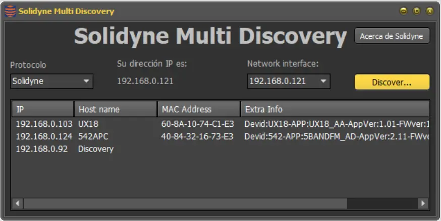
When executed, the installer sets up the application and creates a folder in the Windows Start menu named “Solidyne Discovery”, containing shortcuts to the application and the instruction file.
DANTE/AES67 Module (542APC/A67 models)
1. Stereo output, sending the processed signal.
2. Stereo input.
These options are mutually exclusive and cannot be installed together. The expansions may come pre-installed from the factory or can be added after purchase. They are only supported by devices with serial numbers starting with AD or later.
The expansion module is easy to install but requires disconnecting and opening the unit. It is recommended that installation be performed by qualified technical personnel. The procedure is detailed in the “Optional Accessories and Disassembly Manual,” available at www.solidyne.ar
5.2 STREAMER optional module
5.2.1 Accessing from a LAN
WARNING
Processors equipped with the STREAMER AoIP module feature two Ethernet ports:
ETHERNET CONTROL ETHERNET AoIP
Refer to Figure 1 in Section 2.2 – Rear Panel and Audio Connections.
1. Connect the ETHERNET AoIP port to the LAN using a UTP CAT5 cable.
3. In the Protocol menu of Multi-Discovery, select IP Audio Module and click Discover to locate the STREAMER AoIP module.
4. Double-clicking the item in the Discovery window will open the web interface directly in the default browser. Alternatively, the user can manually enter the IP address in an internet browser (preferably Google Chrome).
5.2.2 Remote Access via Internet
To access the local network remotely over the Internet, 542APC processors equipped with the STREAMER AoIP expansion include a redirection service that eliminates the need for port forwarding and static IP configuration.
This service, provided by a third-party (ZROCK), offers a free access mode that can be activated upon request to the manufacturer.
To activate this service, the user must email soporte@solidyne.ar, requesting the creation of a ZROCK account for remote access, and include the following details:
· Email address to register
· Processor serial number
Audio Processing Core – SOLIDYNE 542APC
Page 39
terface. This allows the user to manage streaming options and access the Hardware Control interface (REMOTE CONTROL).
The access screen prompts for an username and password. Access is available under the BASIC or ADMIN user roles. The default password is 1234, which is shared with the hardware configuration.
For continuous access to the processor, the user must independently subscribe to the service. This service is provided
by a third-party vendor and is not affiliated with Solidyne.
5.2.3 Integrated Control Interface
Processors in the 542APC series equipped with the STREAMER AoIP module include an integrated control in-
Upon logging in with any user role, the initial screen or “HOME” of the integrated interface is displayed.
If the user logs in as BASIC, only access to **REMOTE CONTROL** (hardware configuration) is enabled.
If the user logs in as ADMIN, all configuration options are available.
The HOME screen offers the following options:
HOME: Loads the current screen.
STREAM CFG: Opens the configuration options for streaming services (see below).
REMOTE CONTROL: Opens the remote configuration screen for processing parameters and modulation monitoring.
SYSTEM: Displays options for configuring the local network for the Ethernet control port, system information, and settings for external Internet access. Details are provided later in this section.
UPDATE: Simplified firmware update process. Details are provided later in this section.
REMOTE PLAYER: Allows the user to listen to the processor’s audio over the local network or the Internet. Details are provided later in this section.
LOG OUT: Logs out the user and returns to the login screen.
5.2.4 Streaming Services (STREAM CFG)
The configuration of streaming services is accessed from the STREAM CFG menu option, which presents the following options:
· UP-STREAM (Tx) · RTP-LINK (Tx) · DOWN-STREAM (Rx) · REMOTE PLAYER · SERVICE CFG
5.2.5 Down-Stream Reception (Rx)
The reception of streaming is described first, as it is typically used to link the processor with the station’s studios (known as STL, or Studio to Transmitter Link), by receiving an RTP stream generated by an encoder at the studios.
Page 40
Audio Processing Core – SOLIDYNE 542APC
5.2.5.1 Studio-Transmitter Link
As an example, a scenario for using RTP reception as an STL link is outlined. Note that in this example, the link is established via a point-to-point network connection, not over the Internet.
The Solidyne 542 processor can receive RTP streaming in the following audio formats:
· PCM (recommended), which results in moderate latencies, typically between 15 to 40 ms
· MPEG Layer-3 (mp3)
· Opus (in development)
The support for encoded audio allows links to be established using the Internet with low bandwidth requirements (0.5 Mbps for 192 kbps), but it introduces delays ranging from 200 to 500 milliseconds.
ABOUT LATENCY
WHEN THE STUDIO-PLANT LINK INVOLVES DELAYS GREATER THAN 15 MILLISECONDS, MONITORING IS NOT
POSSIBLE IN THE STUDIOS BY TUNING THE AIR TRANSMISSION.
Those who speak into the air in the studio perceive the delay as an “echo” in the headphones, which makes their task difficult. In these cases, an auxiliary processor can be used in the Studio to
process a console direct output and use it in the monitoring circuit. You don’t need the same level of processing as air, but it
should be similar in compression and dynamics.
Note that to the delay introduced by the link, the latency of the 542 is added, of the order of 9 mS.
The point-to-point data link can be either physical through an Intranet or wireless using microwave links operating in the 5.8 GHz WI-FI or WI-Max communication band. These links have a range of up to 50 km and low costs due to the equipment being mass-produced. The 5.8 GHz band is freely available for Internet communications.
erate a PCM 16/44.1 kHz stream. The processor automatically recognizes the audio format.
Step 1
It is assumed that the equipment is correctly connected to the network via the Ethernet AoIP port.
Step 2
In the DOWN-STREAM (Rx) tab, the following parameters are configured:
Activate reception by setting the RUN/STOP control to RUN.
· In the PROTOCOL field, select RTP. · In the SERVER URL / IP field, enter the IP address
of the encoder (the device generating the streaming from the studio). · In the PORT field, enter the port through which the RTP streaming is received. · The PATH / MOUNT POINT field is not used for RTP. Leave it blank. · Press “Apply” to confirm the values. · The processor will start receiving audio from the studios. The signal level will be displayed on the corresponding indicators.
5.2.5.2 Reception of Public Streaming
The STREAMER AoIP module can receive public streams using the HTTP or MMS protocol, encoded in PCM 16 44.1/48 kHz, MP3, or OPUS. This audio source can operate as the main input or as a backup when a physical input (analog or AES3) is used as the primary input.
5.2.6 UP-STREAM (Icecast/Shoutcast Tx)
The UP-STREAM (Tx) tab allows configuring the transmission to a media server of the Icecast or Shoutcast type.
Figure 39: Basic diagram for streaming connection
In the transmitter plant, the processor acts as a passive receiver and receives the streaming coming from the studio. Only the port, IP address, and audio format need to be configured. The audio codec is defined on the transmitter side. For this example, the studio equipment is configured to gen-
Audio Processing Core – SOLIDYNE 542APC
Figure 40: UpStream Page 41
RUN/STOP: Starts or stops the stream to the server once changes are confirmed with APPLY. To optimize system resources, keep it stopped when the service is not in use. PROTOCOL: Defines whether the server is of the Icecast or Shoutcast type. SERVER IP: IP address of the Icecast/Shoutcast server. PORT: TCP listening port for the server. MOUNTPOINT: Unique name that identifies the stream on the Icecast/Shoutcast server. Stream NAME: Name that identifies the stream. PASSWORD: Access password for publishing on the server (if required). CODEC: Defines the audio format as MP3 or Opus. QUALITY: Bit rate for encoding. APPLY: Applies and saves changes and starts or stops the transmission (depending on the RUN/STOP status).
NOTE The configuration parameters for Icecast/Shoutcast are
provided by the server provider.
5.2.7 RTP LINK
The RTP LINK tab provides configuration options to send audio to a specific IP address. It allows creating point-to-point links via a local network or over the internet. For example, this can be used to link to a second studio or to a transmitter plant (Studio to Transmitter Link). Implementing an RTP link requires advanced knowledge of network configuration.
Figure 41: Streaming RTP
RUN/STOP: Starts or stops the RTP streaming when changes are confirmed with APPLY. To optimize system resources, keep it stopped when the service is not in use. DEST IP: Destination IP address. PORT: Transmission TCP port. PAYLOAD: A numerical value related to the audio format. It is used by the receiving software. CODEC: Audio format for RTP. Supports PCM, Opus, and MP3. QUALITY: Allows defining the bitrate for Opus and MP3 (between 96 and 320 kbps) or the sample rate for PCM (32, 44.1, or 48 kHz).
5.2.8 Remote Listening
This tool is only available in 542APC /AoIP models. It allows remote listening, through the web interface, to the processor’s audio signal. The remote player can be
launched from the HOME screen or from the REMOTE CONTROL screen. Audio is sent via a WebRTC service.
When accessed from a local network terminal, no advanced configurations are required. The remote player will play the audio over the LAN.
When accessed via the Internet, depending on the network infrastructure, a TURN server may be needed. In such cases, the player connects but does not receive audio, reporting to the user that the connection is not possible and a TURN server must be configured.
In STREAM CFG REMOTE PLAYER, information related to the WebRTC service can be accessed. The audio format is Opus, and the user can change the bitrate between 128 and 320 kbps.
The Remote Player takes audio from the Ethernet AoIP output, which can be switched
Documents / Resources
 |
SOLIDYNE 542 APC Audio Processing Core FM and HD Audio [pdf] Owner's Manual 542 APC Audio Processing Core FM and HD Audio, 542 APC, Audio Processing Core FM and HD Audio, Processing Core FM and HD Audio, HD Audio |