![]() Triple Power BMS
Triple Power BMS
Parallel Box-II G2
Installation Manual
Version 4.0 www.solaxpower.com
 eManual in the QR code or at http://kb.solaxpower.com/
Safety
General Notice
- Contents may be periodically updated or revised. SolaX reserves the right to make improvements or changes in the product(s) and the program(s) described in this manual without the prior notice.
- The installation and maintenance can only be performed by qualified personnel who:
• Are licensed and/or satisfy state and local jurisdiction regulations;
• Have good knowledge of this manual and other related documents. - Before installing the device, carefully read, fully understand and strictly follow the detailed instruction of the user manual and other related regulations. SolaX shall not be liable for any consequences caused by the violation of the storage, transportation, installation, and operation regulations specified in this document and the user manual.
- Use insulated tools when installing the device. Individual protective tools must be worn during installation, electrical connection and maintenance.
- Please visit the website www.solaxpower.com of SolaX for more information.
Safety Instruction
For safety reasons, installers are responsible for familiarizing themselves with the contents of the Manual and all warnings before performing installation.
Descriptions of Labels
| CE mark of conformity | |
| Caution, risk of danger | |
 |
Keep the battery system away from open flames or ignition systems |
| Safety glasses must be worn | |
| The system must be disposed of at a proper facility for environmentally-safe recycling. | |
| Protective conductor terminal | |
 www.tuv.com www.tuv.com |
TUV certification |
| Caution, risk of electric shock | |
 |
Keep the battery system away from children |
| Refer to the operating instructions | |
| Do not dispose of the parallel box together with household waste. |
![]() DANGER!
DANGER!
Danger to life due to high voltages in the device!
- All operations of the device relating to electrical connection and installation must be carried out by qualified personnel.
- The device is not to be used by children or persons with reduced physical sensory or mental capabilities, or lack of experience and knowledge, unless they have been given supervision or instruction.
- Children should be supervised to ensure that they do not play with the device.
![]() WARNING!
WARNING!
Risk of electric shock!
- During operation, do not touch any parts other than DC switch and LCD panel of the device.
- Use only attachments recommended or sold by our company. Otherwise, it may result in a risk of fire, electric shock, or injury to person.
- Make sure that the existing wiring is in good condition and that the wire is not undersized.
- Authorized service personnel must use insulated tools when installing or working with this equipment.
- Do not disassemble any parts of the device which are not mentioned in the user manual. The device contains no user-serviceable parts.
- The installation place should be away from humid or corrosive substance.
- Authorized service personnel must disconnect the cables before attempting any maintenance or cleaning or working on any circuits connected to the device.
![]() CAUTION!
CAUTION!
Danger of burn injuries due to hot enclosure parts!
- During operation, the upper lid of the enclosure and the enclosure body may become hot.
- Only touch the lower enclosure lid during operation
![]() CAUTION!
CAUTION!
Possible damage to health as a result of the effects of radiation!
- Do not stay closer than 0.66 ft/20 cm to the device for any length of time.
![]() CAUTION!
CAUTION!
- Pay attention to the weight of the device. Personal injuries may be caused if not handled properly.
- Keep the device away from flammable, explosive materials to avoid fire disaster.
NOTICE!
- Ensure that the installation location meets the following conditions:
1. The building is designed to withstand earthquakes.
2. The location is far from the sea to avoid salt water and humidity, over 0.62 miles/997.79 meters.
3. There are no flammable or explosive materials, at a minimum of 3 ft//0.91 m.
4. The ambience is shady and cool, away from heat and direct sunlight.
5. The temperature and humidity remains at a constant level.
6. There is minimal dust and dirt in area.
7. There are no corrosive gases present, including ammonia and acid vapor.
8. Where charging and discharging, the ambient temperature ranges from 32°F/0°C to 131°F/55°C. For Triple power 3.0: -22°F/-30°C to 131°F/55°C (with heating function); 14°F/-10°C to 131°F/55°C (no heating function). For Triple power 5.8: 32°F/ 0°C to 131°F/55°C (no heating function).
In practice, the requirements of battery installation may be different due to environment and locations. In that case, follow up the exact requirements of the local laws and standards. - The company’s battery module is rated at IP65 and thus can be installed outdoors as well as indoors.
- If the ambient temperature exceeds the operating range, the battery pack will stop running to protect itself. The optimal temperature range for operation is 59°F/15°C to 86°F/30°C. Frequent exposure to harsh temperatures may deteriorate its performance and lifetime.
- For the first installation, the interval among manufacture dates of battery modules shall not exceed 3 months.
- All the product labels and nameplate on the device shall be maintained clearly visible.
- See Warranty for instructions on obtaining service. Attempting to service the device yourself may result in a risk of electric shock or fire and will void your warranty.
Packing List
For use with T-BAT-SYS-HV-5.8:
 |
 |
| Power cable (+) x1 Power cable (-) x1 (6.56ft/200cm) |
Power cable (+) x2 Power cable (-) x2 (7.22ft/220cm) |
 |
 |
| BMS Communication Cable (6.56ft/200cm) x1 CAN/485 Communication Cable (7.22ft/220cm) x2 |
Series-connected plug x2 |
 |
 |
| Expansion tube x2 Expansion Screw x2 Power Cable Disassembling Tool x1 |
Rotation Wrench x1 |
 |
 |
| Grounding Terminal x2 | Documents |
For use with T-BAT-SYS-HV-3.0:
|
|
| Power cable (+) x1 Power cable (-) x1 (6.56ft/200cm) |
Power cable (+) x1 Power cable (-) x1 (7.22ft/220cm) |
 |
|
| Power Cable (Heat+) x1 Power Cable (Heat-) x1 (6.56ft/200cm) |
RS485 Communication Cable (7.22ft/220cm) x2 BMS Communication Cable (6.56ft/200cm) x1 |
|
|
| Expansion tube x2 Expansion Screw x2 Power Cable Disassembling Tool x1 |
Rotation Wrench x1 |
|
|
| Grounding Terminal x2 | Documents |
BMS Parallel Box-II G2:
|
 |
| Power cable (+) x1 Power cable (-) x1 (6.56ft/200cm) |
BMS Communication Cable (6.56ft/200cm) x1 CAN/485 Communication Cable (7.22ft/220cm) x2 |
|
|
| Expansion tube x2 Expansion Screw x2 Power Cable Disassembling Tool x1 |
Rotation Wrench x1 |
|
|
| Grounding Terminal x2 | Documents |
Accessory Kit (For T58):
|
|
| Power cable (+) x2 Power cable (-) x2 (7.22ft/220cm) |
Series-connected plug x2 |
Accessory Kit (For T30):
|
 |
| Power cable (+) x1 Power cable (-) x1 (7.22ft/220cm) |
Power Cable (Heat+) x1 Power Cable (Heat-) x1 (6.56ft/200cm) |
* Please refer to the actual delivery for the accessories.
Installation Site

NOTICE!
- For outdoor installation, precautions against direct sunlight, rain exposure and snow accumulation are recommended.
- Exposure to direct sunlight raises the temperature inside the device. This temperature rise poses no safety risks, but may impact the device performance.
Installation Carrier
 |
 |
| Fire resistant | Be suitable for the dimension (368 x 334 x 153.5 mm) and weight (25 kg) of the device |
Installation Angle

Installation Space

Installation Tools

Additionally Required Materials
| No. | Required Material | Type | Conductor Cross-section |
| 1 | Additional PE cable | Conventional yellow and green wire | 6 mm² |
Mechanical Installation


Terminals of the BMS Parallel Box- Ⅱ G2

| Object | Mark | Description | |
| I | Slave | HEAT+ | Connector “Heat+” of the parallel box to “Heat+” of Slave |
| II | HEAT- | Connector “Heat-” of the parallel box to “Heat-” of Slave | |
| III | BAT+ | Connector “BAT+” of the parallel box to “B+”/”+” of Slave | |
| IV | BAT- | Connector “BAT-” of the parallel box to “B-“/”XPLUG” of Slave | |
| V | S-CAN | Battery module communication of Slave | |
| VI | 485 | Battery module communication of Slave | |
| VII | Main | BAT+ | Connector “BAT+” of the parallel box to “BAT+” of Main |
| VIII | BAT- | Connector “BAT-” of the parallel box to “BAT+” of Main | |
| IX | M-CAN | Battery module communication of Main | |
| X | / | Air Venue | |
| XI | Inverter | BAT+ | Connector “BAT+” of the parallel Box to “BAT+” of inverter |
| XII | BAT- | Connector “BAT-” of the parallel Box to “BAT-” of inverter | |
| XIII | BMS | Connector “BMS” of the parallel Box to “BMS” of inverter | |
| XIV | GND | ||
| XV | ON/OFF | Circuit Breaker | |
| XVI | POWER | Power Button | |
Overview of Installation
1. Connect with T-BAT-SYS-HV-5.8

| Connect with a T-BAT H 5.8 (BMS) and a HV11550 battery module: | Connect with a T-BAT H 5.8 (BMS) and 3 HV11550 battery modules: |
 |
 |
| Connect with a T-BAT H 5.8 (BMS) and 5 HV11550 battery modules: | Connect with a T-BAT H 5.8 (BMS) and 7 HV11550 battery modules: |
 |
 |
2. Connect with T-BAT-SYS-HV-3.0
| Connect with a MC0600 (BMS) and 2 HV10230 battery modules: | Connect with a MC0600 (BMS) and 4 HV10230 battery modules: |
 |
 |
| Connect with a MC0600 (BMS) and 6 HV10230 battery modules: | Connect with a MC0600 (BMS) and 8 HV10230 battery modules: |
 |
 |
* The recommended installation distance between the box and the battery group (including slave group and master group) is 11.81-23.62 inches /300-600 mm, and the distance between the modules is 9.84 inches/250.00 mm.
* It is supported to only connect the slave battery modules. It is not supported to only connect the master battery modules.
* The number of modules connected at the master side and the slave side should be consistent. At most four modules can be connected at one side.
Connecting Cables to Inverter
Cable connection from BMS Parallel box-Ⅱ G2 to the inverter:
“BAT+” to “BAT+”;
“BAT-” to “BAT-“;
“BMS” to “BMS”.
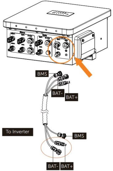
Remember to always keep the unused port plugged.

* It is recommended to protect the cables by using corrugated pipe.
* If you plug the cable into the wrong port, you can insert the power cable disassembling tool into the gap on the side of the joint to unplug the cable easily.
* Please refer to “battery connection” section of the inverter’s user manual/quick installation guide for details about inverter connection.

- If the connector of the T-BAT-SYS-HV-3.0 controller does not match the connector provided with the accessory cable, you can trim the blue connector and replace it with a black connector. The replacement should follow the rule of male-to-male and female-to female connections. The Installation mode of black connector is as follows:
- Wire order for the BMS Communication Cable (the parallel box to the inverter)
Sequence 1 2 3 4 5 6 7 8 BMS / GND / BMS_H BMS_L / A1 B1
Connecting to Battery Modules
1. For BMS Parallel box-Ⅱ G2 + T-BAT H 5.8 + 1/3/5/7 HV11550 battery modules)
From BMS Parallel box-II G2 to T-BAT-SYS-HV-5.8:


* If there is(are) a port(s) that is(are) not wired after wiring is completed, please don’t forget to put the waterproof cap(s) on the port(s).
* To form a complete circuit, connect “-” and “YPLUG” with series-connected cable on the right side of the last battery module.
* Please check T-BAT-SYS-HV-5.8 User Manual/Quick installation guide for detailed tutorial on cable-connecting between T-BAT H 5.8 and HV10230 battery modules.
2. For BMS Parallel box-Ⅱ G2 + MC0600 + 2/4/6/8 HV10230 battery modules
From BMS Parallel box-II G2 to T-BAT-SYS-HV-3.0:


* Regardless of how many battery modules installed, please put a waterproof cap on the communication port of the unconnected port of battery module.
* Please check T-BAT-SYS-HV-3.0 User Manual/Quick installation guide for detailed tutorial on cable-connecting between MC0600 and HV10230 battery modules.
Communication Cable Connection
| For T-BAT-SYS-HV-5.8 (RS485 I, BMS): | For T-BAT-SYS-HV-3.0 (COM1, BMS): |
 |
 |
- There is a protection cover for the RS485 connector. Unscrew the cover and plug one end of the RS485 I communication cable to the RS485 I connector. Tighten the plastic screw nut which is set on the cable with a rotation wrench. The operation is the same as above if connecting to the COM1/BMS connecter.
HV11550 “RS485 I” to Parallel box Slave “485”;
HV10230 “COM1” to Parallel box Slave “S-CAN”;
T-BAT H 5.8 / MC0600 “BMS” to Parallel box Main “M-CAN”.
- Connect the communication cable from the parallel box to the COMM/BMS/RS485 I communication port that is on the left side of the battery module.
* When the BMS Parallel box- Ⅱ G2 is connected to T-BAT-SYS-HV-5.8 battery modules, if the BMS port of T-BAT H5.8 is erroneously connected to the S-CAN port of BMS Parallel box- Ⅱ G2, it can still operate and function normally. However, in this configuration, the master group cannot be upgraded properly.
- The wire order of the communication cable is as follows:
| Sequence | 1 | 2 | 3 | 4 | 5 | 6 | 7 | 8 |
| SLAVE RS485 I | VCC_485 | GND_485 | B2 | N- | P+ | A2 | VCC_485_2 | GND_485 |
| SLAVE S-CAN | VCC_1 | GND | VCC_2 | CANH | CANL | GND | N- | P+ |
| MAIN M-CAN | / | GND | / | BMS_H | BMS_L | / | A1 | B1 |
Ground Connection


Commisioning
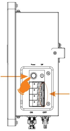
Verify the model number of each battery module to ensure that they are all the same model.
After all battery modules are installed, please follow the following steps to start :
- Turn on T-BAT BMS. Please refer to relevant documents of T-BAT-SYS-HV-5.8 and T-BATSYS-HV-3.0 for details;
- Open the waterproof cover board of the box;
- Move the circuit breaker switch to “ON”;
- Press the Power button to start the box;
- Reinstall the cover board to the box;
- Turn on the inverter DC switch;
- After powering on, make sure to:
• Close the waterproof cover board;
• Secure the circuit breaker cover of BMS Parallel Box-ll G2 by tighten the nuts;
• Secure the circuit breaker cover of T-BAT-SYS-HV-3.0 BMS by tighten the nuts;
• Lock the circuit breaker cover of T-BAT-SYS-HV-5.8 BMS by tighten the screws.
* Frequently pressing the Power button may cause a system error. Allow at least 10 seconds after pressing the Power button prior to making another attempt.
- The black-start function is only used in an off-grid application and when there is no other power supply. To Black-start, hold down the button for 20 seconds until the soc light starts flashing blue to indicate successful black-start.
If the box is started in the black-start mode, remind that even when there is no BMS communication, the port still contains high voltage with risk of electric shock.
If the BMS communication has still not been established within 3 minutes after starting the black-start mode, it indicates that the black start fails to start. - After the BMS Parallel box-II G2 is powered on, if the indicator lights alternate flashing red and green for more than two minutes, and then change to green flashing with the inverter reporting “Batt_Cluster CommuCountMisMatch”, please check the communication connection of the second group of BMS Parallel box-II G2, as well as the power-on status of T-BAT H 5.8 or MC0600 connected to the second group.
- After the BMS Parallel box-II G2 is powered on, if the indicator lights alternate flashing red and green for more than three minutes, and then change to flashing red for one second and off for three seconds, with the inverter reporting “BMS_Internal_Err 1”, it indicates that the corresponding slave at position 1 failed to connect to the communication successfully. According to the error number, please check if the communication line of the slave at the corresponding position is properly connected.
- The BMS Parallel box- II G2 must be connected to two groups of batteries simultaneously in order to function properly, and the number of slaves in both groups must be the same. The second group of BMS Parallel box-Ⅱ G2 must contains a T-BAT Η 5.8 or MC0600. And the two battery circuits connected to the BMS Parallel box-Ⅱ G2 must be all HV11550 or all HV10230, and it is not allowed to connect one group with HV11550 batteries and the other group with HV10230 batteries.
- It is prohibited to plug or unplug the power line during the operation of the BMS Parallel G2. box-
LCD Panel

The LED indicators on the front panel of the BMS and the battery modules indicate the operating status. Description of the status indicators of BMS is shown as follows:
| No. | Status of BMS | Mode |
| 1 | Green LED flashes on 1 sec and off for 4 sec | Inverter sends Idle command |
| 2 | When both groups have faults, the status lights of the two groups will flash red at intervals of 0.5 seconds. The general status light will keep the red light on. When one of the two groups has a fault, and the status light of one group flashes red (light for 1 second and off for 4 seconds), while the other group keeps the green light on. * When the fault is reported, the fault light of the corresponding branch will stay red. |
Upgrade for BMS |
| 3 | The status light of one of the two groups is off if it works normally. The general status light will flash green (light for 1 second and off for 4 seconds) will stay on green light if an inverter is connected. |
Power off |
| 4 | Green LED flashes once every 0.5 sec | Protection |
| 5 | Light off | Normal |
- The capacity indicators show the state of charge (SOC):
When the battery module is neither charging nor discharging, the indicator lights are off.
When the battery module is charging, a part of the blue LED flashes once every 5 seconds, and a part of the blue LED is on.
Take SOC 60% for instance, when in charging state:
- The last two blue LED indicators are on
- The last three blue LED indicators flash once every 5 seconds
When the battery module is discharging, the blue LED indicators flash once every 5 seconds. Take SOC 60% for instance, when in discharging state:
- The last three blue LED indicators flash once every 5 seconds
Technical Data
| T-BAT-SYS-HV-5.8 | T-BAT P 5.8 G2 | T-BAT P 11.5 G2 | T-BAT P 17.3 G2 | T-BAT P 23.0 G2 |
| Nominal voltage [V] | 115.2 | 230.4 | 345.6 | 460.8 |
| Operating voltage [V] | 100-131 | 200-262 | 300-393 | 400-524 |
| Total Capacity [kWh] | 11.5 | 23.0 | 34.6 | 46.1 |
| Usable Capacity [kWh] | 10.3 | 20.7 | 31.1 | 41.4 |
| Nominal power [kW] | 2.8 | 5.7 | 8.6 | 11.5 |
| Max. power [kW] | 4.0 | 8.0 | 12 | 16.1 |
| T-BAT-SYS-HV-3.0 | T-BAT P 3.0 G2 | T-BAT P 6.0 G2 | T-BAT P 9.0 G2 | T-BAT P 12.0 G2 |
| Nominal voltage [V] | 102.4 | 204.8 | 307.2 | 409.6 |
| Operating voltage [V] | 90~116 | 180~232 | 270~348 | 360~464 |
| Total Capacity [kWh] | 6.1 | 12.3 | 18.4 | 24.6 |
| Usable Capacity[kWh] | 5.5 | 11.0 | 16.5 | 22.1 |
| Nominal power [kW] | 2.5 | 5.1 | 7.6 | 10.2 |
| Max. power [kW] | 3.0 | 6.1 | 9.2 | 12.2 |
Contact Information
| UNITED KINGDOM Road, Atherstone, CV9 1FA TURKEY Karatay / Konya / Türkiye USA Beach, CA, US 90806 POLAND ITALY PAKISTAN |
AUSTRALIA GERMANY NETHERLANDS SPAIN tecnico@solaxpower.com BRAZIL SOUTH AFRICA |
Warranty Registration Form
![]()
For Customer (Compulsory)
Name —————— Country ——————
Phone Number —————— Email ——————
Address ——————
State —————— Zip Code ——————
Product Serial Number ——————
Date of Commissioning ——————
Installation Company Name ——————
Installer Name —————— Electrician License No. ——————
For Installer
Module ( If Any )
Module Brand ——————
Module Size(W) ——————
Number of String —————— Number of Panel Per String ——————
Battery ( If Any )
Battery Type ——————
Brand ——————
Number of Battery Attached ——————
Date of Delivery Signature ——————
Please visit our warranty website: https://www.solaxcloud.com/#/warranty or use your mobile phone to scan the QR code to complete the online warranty registration.
 https://www.solaxcloud.com/#/installationGuide
For more detailed warranty terms, please visit SolaX official website: www.solaxpower.com to check it.
![]()
SolaX Power Network Technology (Zhejiang) Co., Ltd.
Add.: No. 278, Shizhu Road, Chengnan Sub-district, Tonglu County, Hangzhou, Zhejiang, China
E-mail: info@solaxpower.com
Copyright © SolaX Power Network Technology (Zhejiang) Co., Ltd. All rights reserved.

Documents / Resources
 |
SolaX Power Box-II G2 Triple Power BMS Parallel [pdf] Instruction Manual G2, Box-II G2 Triple Power BMS Parallel, Box-II G2, Triple Power BMS Parallel, BMS Parallel, Parallel |