![]() LFM127-11 One-Way Flow Altitude Control Valve with Delayed Opening Feature
LFM127-11 One-Way Flow Altitude Control Valve with Delayed Opening Feature
User Manual Series LFM127-11 / LFM6127-11
Sizes: 11/4″ to 24″
Operation and Maintenance
![]() WARNING
WARNING
![]() Read this Manual BEFORE using this equipment.
Read this Manual BEFORE using this equipment.
Failure to read and follow all safety and use information can result in death, serious personal injury, property damage, or damage to the equipment.
Keep this Manual for future reference.
![]() WARNING
WARNING
Local building or plumbing codes may require modifications to the information provided.
You are required to consult the local building and plumbing codes prior to installation. If the information provided here is not consistent with local building or plumbing codes, the local codes should be followed. This product must be installed by a licensed contractor in accordance with local codes and ordinances.
![]() WARNING
WARNING
Need for Periodic Inspection/Maintenance: This product must be tested periodically in compliance with local codes, but at least once per year or more as service conditions warrant. All products must be retested once maintenance has been performed. Corrosive water conditions and/or unauthorized adjustments or repair could render the product ineffective for the service intended. Regular checking and cleaning of the product’s internal and external components helps assure maximum life and proper product function.
NOTICE
For Australia and New Zealand: Pipeline strainers should be installed between the upstream shutoff valve and the inlet of the backflow preventer. It’s important that this device be tested periodically in compliance with local codes, but at least once per year or more as service conditions warrant. If installed on a fire sprinkler system, all mechanical checks, such as alarm checks and backflow preventers, should be flow tested and inspected internally in accordance with NFPA 13 and NFPA 25.
Watts product specifications in U.S. customary units and metric are approximate and are provided for reference only. For precise measurements, please contact Watts Technical Service. Watts reserves the right to change or modify product design, construction, specifications, or materials without prior notice and without incurring any obligation to make such changes and modifications on Watts products previously or subsequently sold.
Engineering Specification
LEAD FREE*
Series LFM127-11
One-Way Flow Altitude Control Valve with Delayed Opening Feature Full Port Ductile Iron Single Chamber Valve
Features
- Designed for Tank Fill applications
- Opens when Tank head pressure is below setpoint
- Closes when Tank head pressure is above setpoint
- Delayed Opening Feature allows calculated Tank turnover
- Tank Sense Line is field installed (connected to reservoir or standpipe)
- Adjustable Opening and Closing Speed
- Altitude and Delayed Opening setpoints are separately adjustable

Standard Components
- Main Valve (M100 – Single Chamber)
- Delayed Opening Control
- Model 22-1 Accelerator Control
- Altitude Control
- Check Valve
- Adjustable Opening Speed
- Adjustable Closing Speed
- 3-Way Ball Valve
P – Position Indicator
X – Isolation Cocks
Options and Accessories
- FC – Flo-Clean Strainer
- Y – Y-Strainer (Replaces Flo-Clean)
- L – Limit Switch
Operation
The One Way Flow Altitude Automatic Control Valve (ACV) with Delayed Opening Feature is designed to open, allowing flow into a reservoir or elevated storage tank (tank fill), and close drip tight when high water level is achieved. The valve also has an adjustable delayed opening feature, allowing a calculated “draw-down” of water level, before opening for tank fill operation. The Altitude Pilot remotely senses static tank head pressure (water level) through a field installed sensing line, and directs pressure into and out of the cover chamber of the 3-way Accelerator Pilot. When the cover of the Accelerator Pilot is pressurized, the main valve cover chamber is vented downstream (dry drain) or to atmosphere (wet drain), causing the valve to open fully. When the cover of the Accelerator Pilot is de-pressurized, the main valve cover chamber is connected to upstream pressure, causing the valve to close drip tight. As water level decreases, static tank head pressure falls below the adjustable setpoint of the Altitude Pilot, causing it to pressurize the cover of the Accelerator Pilot, opening the valve. As water level increases, static tank head exceeds the adjustable setpoint of the Altitude Pilot, causing it to depressurize the cover of the Accelerator Pilot, closing the valve drip tight. Valve opening and closing speeds are separately adjustable. The Position Indicator with Air Bleed Petcock allows for visual indication of valve position, and easy venting of air entrapped in the main valve cover chamber.
The adjustable Delayed Opening Feature “holds” high level static tank head pressure in the Altitude Pilot, causing the main valve to remain closed as water level decreases. When static tank head pressure falls below the setpoint of the Delayed Opening Pilot, the Altitude Pilot commands the main valve to open for tank fill operation. Reservoir filling can be “delayed” until water level falls 3-15 feet (adjustable) below desired shut-off point to increase water circulation through the tank.
Specify Tank height PRIOR to ordering.
* The wetted surface of this product contacted by consumable water contains less than 0.25% of lead by weight.
NOTICE
The information contained herein is not intended to replace the full product installation and safety information available or the experience of a trained product installer. You are required to thoroughly read all installation instructions and product safety information before beginning the installation of this product.
ACV Schematic
M Series Basic Valves
One-Way Flow Altitude Control Valve with Delayed Opening Feature Full Port Ductile Iron Single Chamber Basic Valve
This Watts Automatic Control Valve (ACV) is a full port, single chamber basic valve that incorporates a one-piece disc and diaphragm assembly. This assembly is the only moving part within the valve allowing it to open, close, or modulate as commandedby the pilot control system.
Watts ACV Main Valves are Lead Free. The Watts ACV piloting system contains Lead Free* components, ensuring all of our configurations are Lead Free compliant. Globe Pattern Single Chamber Basic Valve (M100) Angle Pattern Single Chamber Basic Valve (M1100)

![]()
Standard Materials
| Body and Cover: | Ductile Iron ASTM A536 |
| Coating: | NSF Listed Fusion Bonded Epoxy Lined and Coated |
| Trim: | 316 Stainless Steel |
| Elastomers: | Buna-N (standard) EPDM (optional) Viton™ (optional) |
| Nut, Spring and Stem: | Stainless Steel |
| Anti-Scale (Optional): | Xylan Coated Stem and Seat |
Viton™ is a trademark of The Chemours Company FC, LLC
Operating Pressure
Threaded = 400psi (27.6 bar)
150# Flanged = 250psi (17.2 bar)
300# Flanged = 400psi (27.6 bar)
Grooved End = 400psi (27.6 bar)
Operating Temperature
Buna-N: 160°F (71°C) Maximum
EPDM: 300°F (140°C) Maximum
Viton™: 250°F (121°C) Maximum
Epoxy Coating**: 225°F (107°C) Maximum
** Valves can be provided without internal epoxy coating consult factory
ACV Schematic – Series LFM127-11
Flow Data
- Maximum continuous flow based on velocity of 20 ft. per second.
- Maximum intermittent flow based on velocity of 25 ft. per second.
- Minimum flow rates based on a 20-40 psi pressure drop.
- The Cv Factor of a value is the flow rate in US GPM at 60°F that will cause a 1psi drop in pressure.
- Cv factor can be used in the following equations to determine Flow (Q) and Pressure Drop (∆P):
- The Cv factors stated are based upon a fully open valve.
- Many factors should be considered in sizing control valves including inlet pressure, outlet pressure and flow rates.
- For sizing questions including cavitation analysis consult Watts with system details.

![]()
ACV Schematic – Series LFM127-11
Basic Valve

| Item | Description | Material |
| 1 | Pipe Plug | Lead Free Brass |
| 2 | Cover | ASTM A536 65-45-12 Epoxy Coated Ductile Iron |
| 3 | Cover Bearing | ASTM A276 304 Stainless Steel |
| 4 | Stud with Cover Nut and Washer |
ASTM A570 Gr.33 Zinc Plated Steel |
| 5 | Body | ASTM A536 65-45-12 Epoxy Coated Ductile Iron |
| 6 | Spring | ASTM A276 302 Stainless Steel |
| 7 | Stem Nut | ASTM A276 304 Stainless Steel |
| 8 | Lock Washer | ASTM A276 304 Stainless Steel |
| 9 | Stem Washer | ASTM A276 304 Stainless Steel |
| 10 | Diaphragm Washer | ASTM A536 65-45-12 Epoxy Coated Ductile Iron |
| 11 | Diaphragm* | Buna-N (Nitrile) |
| 12 | Disc Retainer | ASTM A536 65-45-12 Epoxy Coated Ductile Iron |
| 13 | Seat Disc* | Buna-N (Nitrile) |
| 14 | Spacer Washer* x5 | NY300 Fiber* |
| 15 | Disc Guide | ASTM A743 CF8M (316) Stainless Steel |
| 16 | Shaft | ASTM A276 304 Stainless Steel |
| 17 | Seat Ring** | ASTM A743 CF8M (316) Stainless Steel |
| 17A | Seat Screw (8″ and Larger) | ASTM A276 304 Stainless Steel |
| 18 | Seat Gasket* | Buna-N (Nitrile) |
NOTICE
Installation: If unit is installed in any orientation other than horizontal (cover up) OR extreme space constraints exist, consult customer service prior to or at the time of order.
Dimensions
Flanged and Threaded Dimensions
Grooved End Dimensions
ACV Standard Components
LEAD FREE*
Model 27
Altitude Pilot
Size: 1/8″ NPT Actuation Ports (1/4″ NPT Sense Line Port)
The Model 27 Altitude Pilot is a hydraulically operated, diaphragm actuated, spring loaded 3-port pilot designed to open or close based upon static tank head pressure versus an adjustable spring setting. It directly monitors tank head pressure by a contractor field installed Sensing Line. The large diaphragm area causes the Model 27 to be sensitive to slight changes in tank head pressure.
The Model 27 Altitude Pilot works in conjunction with a 3-Way Accelerator Pilot (Model 22 or Model 22-1) to open and close the Main Valve.
As water level decreases, the sensed tank head pressure falls below the control setpoint of the Model 27, causing it to pressurize the cover of the 3-Way Accelerator, allowing the Main Valve to open for filling operations. The valve will either open fully or regulate to fill the tank based upon the pilot control system installed on the Main Valve.
As water level increases, the sensed tank head pressure increases above the control setpoint of the Model 27, causing it to depressurize the cover of the 3-Way Accelerator, closing the Main Valve.
Turning the Adjusting Screw clockwise increases the control setting, increasing tank level.
Turning the Adjustment Screw counterclockwise lowers the control setting, decreasing tank level.
The Model 27 may be equipped with an optional Altitude Gauge or Delayed Opening Pilot in the sensing line to allow for increased tank turn-over. Consult your factory representative for details.
Specifications
| Body: | Brass Alloy C46500 (standard) Stainless Steel (optional) |
| Adjustment Spring: | Steel |
| Adjustment Range: | 5-20 feet (2 – 6 meters) 10-75 feet (3 – 23 meters) 50-225 feet (15- 69 meters) |
| Elastomers: | Buna-N (standard) EPDM (optional) |
* The wetted surface of this product contacted by consumable water contains less than 0.25% of lead by weight.
Model 27
Altitude Pilot

| Item | Description |
| 1 | Adjusting Screw |
| 2 | Jam Nut |
| 3 | Cap |
| 4 | Spring Housing |
| 5 | Upper Chamber |
| 6 | Stud with Cover Nut and Washer x8 |
| 7 | Lower Chamber |
| 8 | Upper Spring Guide |
| 9 | Spring (see below) |
| 10 | Lower Spring Guide |
| 11 | Upper Jam Nut |
| 12 | Lower Jam Nut |
| 13 | Upper Diaphragm Washer |
| 14 | Diaphragm* |
| 15 | Lower Diaphragm Washer |
| 16 | Shaft |
| 17 | Bearing |
| 18 | O-Ring* |
| 19 | Machine Screw |
| 20 | F23 Body |
| 21 | Stem |
| 22 | Spring |
| 23 | O-Ring* |
| 24 | F23 Seat |
| 25 | Disc and Retainer* |
| 26 | Spring |
| 27 | Lower Cap |
| 28 | O-Ring* |
LEAD FREE*
Model LFCP15
Pressure Reducing Pilot
Size:3⁄8″ NPT
The Model LFCP-15 is a direct acting, diaphragm actuated Pilot that automatically reduces a higher upstream (inlet) pressure to a constant downstream (outlet) pressure. It is normally held open by the force of the adjustable spring setting above the diaphragm. The Pilot modulates towards a closed position when outlet pressure exceeds the spring setpoint, lowering the delivery pressure. It modulates towards an open position when the outlet pressure falls below the spring setpoint, increasing the delivery pressure. When a Model LFCP-15 is installed in the piping circuit of an Automatic Control Valve, its throttling action causes the Main Valve to throttle open or closed accordingly. Turning the adjust- ment screw clockwise raises the control setpoint, increasing main valve outlet pressure. Turning the adjustment screw counterclockwise lowers the control setpoint, decreasing Main Valve outlet pressure. The Model LFCP-15 is equipped with one 3/8″ NPT inlet and two outlet ports for ease of installation. The unused outlet port may be plugged or used as a pressure gauge connection.

Specifications
| Body Material: | Lead Free Copper Silicon Alloy CF8M (316) Stainless Steel (optional) |
| Seat: | 316 Stainless Steel |
| Elastomers: | Buna-N (standard) Viton™ (optional) EPDM (optional) |
| Inlet Pressure Rating: | 400psi (27.6 bar) maximum |
| Adjustment Range: | 30-300psi (2.1 – 20.7 bar) (standard) 2-30psi (0.15-2 bar) (optional) |
Viton™ is a trademark of The Chemours Company FC, LLC
* The wetted surface of this product contacted by consumable water contains less than 0.25% of lead by weight.
| Item | Description |
| 1 | Adjusting Screw |
| 2 | Nut |
| 3 | Spring Housing |
| 4 | Cap Screw |
| 5 | Body |
| 6 | Seat |
| 7 | Spring Guide |
| 8 | Spring |
| 9 | Nut |
| 10 | Belleville Washer |
| 11 | Diaphragm Washer |
| 12 | Diaphragm* |
| 13 | Yoke |
| 14 | Disc and Retainer Assembly* |
| 15 | O-Ring* |
| 16 | Bottom Cap |
LEAD FREE
Model 22-1
3-Way Accelerator Control
Size: 1/2″
The Model 22-1 3-Way Accelerator Pilot is a diaphragm-actuated control with three separate ports: Supply, Common and Exhaust.
It is normally installed in the pilot control circuit of an Automatic Control Valve, with the supply port connected to upstream pressure, the common port connected to the Main Valve cover chamber, and the exhaust port vented either downstream or to atmosphere. Its large 1/2″ ports offer increased capacity, and allow smaller ported devices, such as a 3-Way Solenoid, Float or Altitude Pilot, to operate the Main Valve open and closed. When the cover of the Accelerator Pilot is de-pressurized, the main valve cover chamber is connected to upstream pressure, causing the valve to close drip tight.
When the cover of the Accelerator Pilot is pressurized, the main valve cover chamber is vented downstream (dry drain) or to atmosphere (wet drain), causing the valve to pen
fully.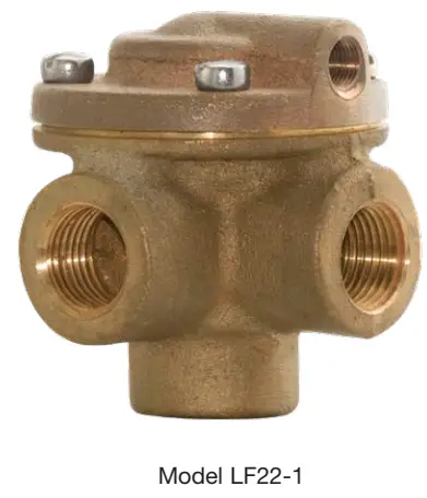

Specifications
| Size: | 1/2″ |
| Body Material: | C87800 Silicone Bronze (std) CF8M Stainless Steel (opt) |
| Elastomers: | Buna-N (std) Viton™ (opt) EPDM (opt) |
| Inlet Pressure Rating: | 400 psi maximum |
Viton™ is a trademark of The Chemours Company FC, LLC
* The wetted surface of this product contacted by consumable water contains less than 0.25% of lead by weight.
| Item | Description |
| 1 | Nut |
| 2 | Lock Washer |
| 3 | Upper Diaphragm |
| 4 | Diaphragm* |
| 5 | Lower Diaphragm Washer |
| 6 | Spring |
| 7 | Stem |
| 8 | Spool |
| 9 | O-Ring* |
| 10 | O-Ring* |
| 11 | Retainer |
| 12 | O-Ring* |
| 13 | O-Ring Washer |
| 14 | Lock Washer |
| 15 | Nut |
LEAD FREE*
Model CK
Check Valve
Size: ¼” – 1″ NPT
Model CK Check Valves are pilot line check valves. In typical applications these low cracking pressure in-line checks provide a hydraulic check feature to a pilot system. When the main valve outlet pressure exceeds inlet pressure, fluid is directed from the outlet to the main valve cover. This causes the main valve to close until inlet pressure is again greater than outlet.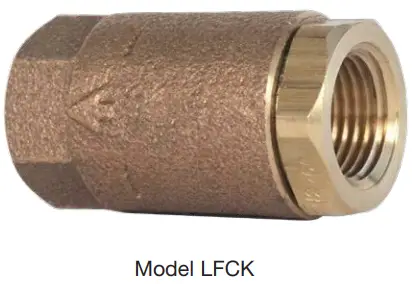

Specifications
| Standard Material: | Brass Housing and Body Stainless Steel Indicating Rod |
| Optional Material: | Stainless Steel Housing and Body Disc Viton™ (1/4″ – ½”) PTFE (1″) |
| Pressure Rating: | 400psi (27.6 bar) |
Viton™ is a trademark of The Chemours Company FC, LLC
* The wetted surface of this product contacted by consumable water contains less than 0.25% of lead by weight.
LEAD FREE*
Model LFFC
Flow Control
Size: ½” NPT
A Flow Control is an adjustable device used for tuning valve performance. It can be installed to either control the opening or closing the speed of the automatic control main valve. When the flow is in the direction of the needle the flow control is an adjustable restriction. In the free flow direction the seat moves out of the flow path to all unrestricted flow.


Specifications
| Size: | 1/2″ NPT |
| Body Material: | Lead Free Brass Stainless Steel (optional) |
| Seat: | Lead Free Brass |
| Needle: | Stainless Steel (304) |
| Elastomers: | Buna-N (standard) |
* The wetted surface of this product contacted by consumable water contains less than 0.25% of lead by weight.
LEAD FREE*
Series LFB6780-M1
2-Piece, Full Port,
Lead Free* Diverter Ball Valves
Sizes: 1⁄4″ – 2″
Series LFB6780-M1 2-Piece, Full Port, Lead Free* Copper Silicon Alloy Diverter Ball Valves are designed to divert liquids and gases in commercial and industrial applications. The LFB6780-M1 full port orifice ensures minimal pressure drop, while PTFE seats and stainless steel ball provide lasting service. The LFB6780-M1 features Lead Free* construction to comply with Lead Free* installation requirements.

Materials
| Handle Nut: | Zinc Plated Carbon Steel |
| Handle: | Zinc Plated Carbon Steel with Vinyl Insulator |
| Packing Nut: | Brass |
| Stem Packing: | PTFE |
| Thrust Bearing: | PTFE |
| Stem: | Stainless Steel |
| Body: | Lead Free Copper Silicon Alloy |
| Seats: | PTFE |
| Ball: | Stainless Steel |
| Adapter: | Lead Free Copper Silicon Alloy |
| Body Seal: | PTFE (1 ¼” – 2″) |
| Temperature Range | Maximum Working Pressure |
| 0°F – 350°F (-18°C – 177°C) @50psi (3.5 bar) | 400psi (28 bar) WOG non-shock @ 100°F (38°C) |


LEAD FREE*
Model 50
Position Indicator
When specified as an option on a Control Valve, the Model 50 Position Indicator is installed in the topmost cover port of the Main Valve and allows for visual indication of valve position. The Model 50 is also very useful during valve start-up and troubleshooting procedures.
A stainless steel indicating rod threads into the tapped portion of the Main Valve stem and moves inside of a cylindrical Pyrex sight tube. The indicating rod travels up and down, following Main Valve stem movement. The housing protects the sight tube and indicating rod, and allows visibility on two sides. The screw driver operated test cock installed on the top of the Model 50 housing provides a controlled method of removal of air from the cover chamber during start-up or troubleshooting of the Main Valve.

Specifications
| Standard Material: | Stainless Steel Housing and Body Stainless Steel Indicating Rod Lead Free Test Cock Pyrex Sight Tube |
| Optional Material: | Stainless Steel Test Cock |
| Pressure Rating: | 400psi (27.6 bar) |
* The wetted surface of this product contacted by consumable water contains less than 0.25% of lead by weight.
| Item | Description |
| 1 | Test Cock |
| 2 | Housing |
| 3 | Gasket |
| 4 | Pyrex Sight Tube |
| 5 | Body |
| 6 | Indicating Rod |
| 7 | Stem Adaptor (8″ or Larger) |
Dimensions
| Valve Size (in) | Dimension (in) |
| 11/4 – 11/2 | 73/8 |
| 2 | 47/8 |
| 21/2 | 47/8 |
| 3 | 47/8 |
| 4 | 5 |
| 6 | 5 |
| 8 | 57/8 |
| 10 | 57/8 |
| 12 | 71/4 |
| 14 | 71/4 |
| 16 | 71/4 |
| 18* | 71/4 |
| 20* | 71/4 |
| 24* | 71/4 |
LEAD FREE*
Model BV
Ball Valve
Size: ¼” – 1″ NPT
Model BV Ball Valves are used in pilot lines to provide a positive shutoff in any override or maintenance situation for simple trouble shooting. This 2-piece, full port valve features: bottom loaded stems, PTFE seats and packing.

Specifications
| Standard Material: | Copper Silicon Alloy Body and Adaptor Chrome Plated Ball |
| Optional Material: | Stainless Steel Housing, Body and Adaptor Stainless Steel Ball |
| Pressure Rating: | Stainless Steel Housing, Body and Adaptor |
| Temp Rating: | Stainless Steel Ball |
The wetted surface of this product contacted by consumable water contains less than 0.25% of lead by weight.

| Size | Dimensions | Weight | ||||||
| C | H | L | ||||||
| in. | in. | mm | in. | mm | in. | mm | lbs. | kg. |
| 1/4 | 1 13/16 | 46 | 3 7/16 | 87 | 13/4 | 45 | 0.4 | 0.2 |
| 3/8 | 1 13/16 | 46 | 3 7/16 | 87 | 13/4 | 45 | 0.4 | 0.2 |
| 1/2 | 1 13/16 | 46 | 3 7/16 | 87 | 1 15/16 | 50 | 0.4 | 0.2 |
| 3/4 | 2 1/4 | 57 | 4 | 101 | 2 5/16 | 59 | 0.8 | 0.3 |
LEAD FREE*
Model LF60
Flo-Clean Strainer
Size: 1/4″ – 3/4″ NPT
Model LF60 Flo-Clean Strainers are used to filter the fluid passing through the pilot circuit, and provide protection to pilot circuit speed controls and pilots. It is installed in the inlet body port of the Main Valve, exposing the strainer element to main line flow.
The currents and flow across the screen create a self-scouring effect, cleaning the filter element.
Specifications
| Body Material: | Lead Free Brass (standard) Stainless Steel (optional) |
| Pressure Rating: | 400psi (27.6 bar) |
| Filter Element: | Monel |
| Screen Mesh: | 40 Mesh (standard) |

| A | B |
| Male Pipe Thread in. | Female Pipe Thread in. |
| 1/4 | 1/8 |
| 3/8 | 1/4 |
| 1/2 | 3/8 |
* The wetted surface of this product contacted by consumable water contains less than 0.25% of lead by weight.
LEAD FREE*
Model LF60-1
Y-Pattern Strainer
Size: 1/4″ – 3/4″ NPT
Model LF60-1 Y-Pattern Strainers are used to filter the fluid passing through the pilot circuit, and provide protection to pilot circuit speed controls and pilots. The filter element can be accessed for cleaning by removing the clean-out cap, or may be cleaned by installing an optional “blow-down” ball valve.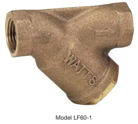

Dimensions
| SIZE | DIMENSIONS | WEIGHT | ||||
| in. | A | B | lbs. | kgs. | ||
| in | mm | in | mm | |||
| 1/4 | 211/16 | 68 | 111/16 | 43 | 1.7 | 0.77 |
| 3/8 | 211/16 | 68 | 111/16 | 43 | 1.7 | 0.77 |
| 1/2 | 3 | 76 | 2 | 51 | 1.7 | 0.77 |
| 3/4 | 35/16 | 84 | 25/16 | 59 | 1.7 | 0.77 |
Specifications
| Body Material: | Lead Free Copper Silicon Alloy CF8M (316) Stainless Steel (optional) |
| Retainer Cap: | Lead Free Copper Silicon Alloy |
| Cap Gasket: | EPDM |
| Pressure Rating: | 400psi (27.6 bar) |
| Filter Element: | 304 Stainless Steel |
| Mesh Options: | 60 Mesh (standard) 100 Mesh (optional) |
* The wetted surface of this product contacted by consumable water contains less than 0.25% of lead by weight.
LEAD FREE*
Model 51
Single Limit Switch
The Model 51 Single Limit Switch provides visual indication of valve position, as well as remote electrical indication of “valve open” or “valve closed”. The single pole double throw MicroSwitch can be connected to open or close an electrical circuit when the valve opens or closes. The adjustable collar is normally set to contact the trip arm when the main valve is closed. The collar can be positioned on the stem by loosening the set-screw to actuate the switch at the desired point of valve travel.


Specifications
| Body Material: | Stainless Steel |
| Elastomers: | Buna-N (standard) EPDM (optional) Viton™ (optional) |
| Enclosure: | NEMA 1, 3, 4 and 13 General Purpose (standard) NEMA 1,7 and 9 Explosion Proof (optional) |
| Electrical: | Form C SPDT Switch 15 amp. 125, 250 or 480 VAC ½ amp. 125 VDC ¼ amp. 250 VDC ½” Conduit Connection |
Viton™ is a trademark of The Chemours Company FC, LLC
* The wetted surface of this product contacted by consumable water contains less than 0.25% of lead by weight.
Parts List
| Item | Description |
| 1 | Limit Switch |
| 2 | Bracket |
| 3 | Stem |
| 4 | Trip collar |
| 5 | Set Screw |
| 6 | Cap |
| 7 | Wiper Ring* |
| 8 | O-Ring* |
| 9 | Guide |
| 10 | O-Ring* |
| 11 | Polypak* |
| 12 | Locknut |
| 13 | Body |
| 14 | Pin |
| 15 | Coupling |
Installation, Operation and Maintenance
– Series LFM127-11
Installation
Start-up of an automatic control valve requires that proper procedures be followed. Time must be allowed for the valve to react to adjustments and the system to stabilize. The objective is to bring the valve into service in a controlled manner to protect the system from damaging over-pressure.
- Prior to installation, flush line to remove debris.
- Install valve so the flow arrow matches flow through the line, and gauges to monitor valve inlet and outlet pressures. A Position Indicator can be installed to provide visual indication of valve position and operation without disassembly.
- Install isolation valves upstream and downstream of the main valve.
Note: If using butterfly valves, ensure valve disc does not contact the main valve. - Provide adequate clearance for valve servicing and maintenance. Refer to valve servicing dimensions on next page. Avoid installing valves 6″ and larger in the vertical position (main valve stem horizontal). Automatic Control Valves (ACVs) are designed for horizontal in-line installation, with the cover facing up (main valve stem vertical). Slow operation or premature stem and guide wear may occur if valve is not installed according to factory recommendations. Consult factory for detailed engineering review prior to ordering if valve is to be installed other than horizontally in-line.
- If valve is equipped with a pilot control system, extra precautions should be made during installation to protect the piping circuit from damage. Only remove the pilot control system from the valve if necessary. Tubing and fittings should be kept clean and replaced exactly as removed. Consult appropriate hydraulic schematic to ensure proper re-assembly.
- Check to confirm that the sense line is installed and connected.
- Installation of a pressure gauge on the sense line of the tank full-delayed opening system will assist in adjustment of setpoint. The amount of pressure drop can be read at the time the main valve starts opening. 8. After installation, vent entrapped air from valve cover and pilot system by following instructions in the Setting the Altitude Controls section on the following page.
Valve Servicing Dimensions

The following tables detail the recommended minimum valve servicing dimensions.
Globe
Angle
| Size (in) | 11/4 | 11/2 | 2 | 21/2 | 3 | 4 | 6 | 8 | 10 | 12 | 14 | 16 |
| C (in) | 16 | 16 | 20 | 22 | 22 | 24 | 32 | 34 | 38 | 44 | 48 | 52 |
| D (in) | 10 | 10 | 12 | 14 | 14 | 16 | 24 | 26 | 28 | 30 | 34 | 40 |
Setting the Altitude Controls
STEP 1
Pre-set pilots as noted:
Altitude Control – Adjust OUT, counterclockwise, backing pressure off the spring. This simulates a low tank setting which can be gradually increased to the desired setting.
Opening and Closing Speed – Turn the adjustment screws on the Closing Speed and Opening Speed Controls, if the main valve is so equipped, OUT, counterclockwise, 1½ to 2½ turns from full closed position.
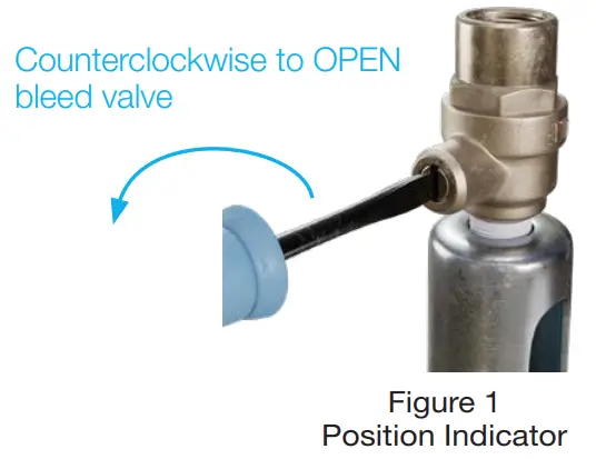
STEP 2
To ensure proper operation, any trapped air will need to be bled off the valve cover during startup. The ACV includes a bleed valve, use a flat head screwdriver to slowly open the valve (See Figure 1).
STEP 3
Pressure the line, by opening the upstream isolation valve slowly. Air is vented through the air bleed valve. Tighten the fitting when liquid begins to vent (See Figure 1).
Repeat the process until no air is trapped in the system.
Setting the Altitude Pilot
STEP 4
Slowly open the downstream isolation valve.

STEP 5
If the valve remains closed as indicated by the stem position in the position indicator (See Figure 2) and the tank level is known to be below the desired level, SLOWLY turn the adjustment screw IN, clockwise, by ¼ to ½ turn increments (Figure 3).
This will cause the valve to start opening, filling the tank. Additional clockwise adjustment may be necessary to raise the level to the overflow line.
STEP 6
When the required level is reached, or if the tank is overflowing, SLOWLY turn the adjustment screw OUT, counterclockwise, in ¼ to ½ turn increments (See Figure 4). A small amount of water will discharge from the vent/exhaust line of the Altitude control, signaling the port connection changes of both the Altitude Control and accelerator. The valve will start closing as indicated by the position indicator stem movement.
The following is dependent upon the installation/application and may not be required on all valves: When the valve is closed, the Altitude control screw adjustment may be turned OUT, counterclockwise, an additional ¼ to ½ turn. This will lower the shut-off level slightly below the tank over-flow mark, eliminating any wave action discharge from the over-flow pipe.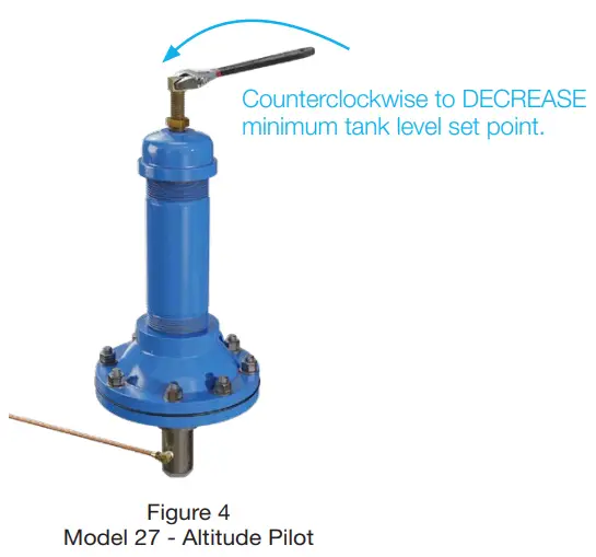
STEP 7
Opening Speed Flow Control Adjustment: The Opening speed needle valve restricts flow out of the cover of the main valve.
If valve opening is too slow, turn the adjustment screw OUT, counterclockwise, increasing the rate of opening (See Figure 5B).
If valve opening is too quick, turn the adjustment screw IN, clockwise, decreasing the rate of opening (See Figure 5A).
STEP 8
Closing Speed Control Adjustment: The closing speed needle valve regulates fluid pressure into the main valve cover chamber, controlling the valve closing speed. If valve closing is too slow, turn the adjustment screw OUT, counterclockwise, increasing the rate of closing.

Setting the Delayed Opening Control
STEP 9
Adjust the tank draw-down Delayed Opening Control by turning the adjustment screw IN, clockwise, to increase (See Figure 6A), or OUT, counterclockwise, to decrease opening delay (See Figure 6B) .
Installation, Operation and Maintenance
– Series LFM127-11
Automatic Control Valve Maintenance Schedule
To ensure peak performance and longevity of your automatic control valve, Watts/Ames recommends following the below standard maintenance schedule.
- Monthly Maintenance
– Visual inspection of valve(s) for leaks
– Inspect for proper operation(s); exercise valve. - Quarterly Maintenance
– Conduct monthly inspection.
– Validate/Re-establish necessary setpoints of controls/pilots. - Annual Maintenance
– Conduct monthly & quarterly inspections.
– Inspect & clean all strainers.
– Inspect valve coating, touch up as required. - 3-5 Year Maintenance
– Conduct monthly, quarterly, & annual maintenance.
– Inspect & replace valve elastomers (diaphragm, O-rings,
valve/pilot seats)
– Re-establish necessary set points of controls/pilots.
Troubleshooting Guide
![]() WARNING
WARNING
Warning: The valve cannot be serviced under pressure.
Upstream and downstream Isolation Valves must be installed to protect system piping. Accurate diagnosis and troubleshooting requires the valve to open fully, and may subject downstream piping and equipment to high pressure and/or flow rates. The downstream Isolation Valve should be kept closed while diagnosing the valve.
Extreme caution should be used while performing the troubleshooting techniques listed below.
Recommended tools for diagnosis: (3) PRESSURE GAUGES, installed to monitor the inlet pressure, outlet pressure, and cover chamber pressure. If included, a POSITION INDICATOR should be installed to visually assess the position of the disc & diaphragm assembly.
Test 1: Diaphragm Seal Test
- Close upstream & downstream isolation valves. Close pilot isolation valves or remove pilot control tubing to isolate valve cover from incoming fluid & pressure. Remove uppermost cover plug, test cock, or limit switch.
- With the valve cover chamber vented to atmosphere, partially open the upstream isolation valve, allowing incoming pressure to lift the disc & diaphragm assembly. A volume of water will be displaced from the cover chamber as the valve opens; consult valve specification sheets for approximate cover capacity. A continuous flow of water from the open port indicates a damaged diaphragm or loose disc & diaphragm assembly. Disassemble valve and replace diaphragm or tightendisc & diaphragm assembly.
Test 2: Seat Seal Test
- Close downstream isolation valve and install pressure gauges on an open inlet and outlet port of main valve.
- Open upstream isolation valve to allow pressure on to the valve cover. Allow valve to fully close.
- Monitor downstream pressure gauge; reading should hold steady below incoming pressure. If pressure on downstream side rises to match upstream pressure, leakage is occurring through the seat of the main valve. Disassemble valve, inspect and repair/replace any required parts.
a. If gauge pressure rises to match outlet pressure (downstream of closed isolation valve) yet remains below inlet pressure, the isolation valve may be leaking as opposed to main valve seat.
Test 3: Freedom of Movement/Valve Travel Test
- Close upstream and downstream isolation valves. Install valve position indicator.
- Partially open upstream isolation valve and allow cover to fill with fluid & pressure, closing the valve fully. Mark the position indicator’s full closed position.
- Isolate cover chamber from receiving fluid and pressure by closing isolation valves or removing control tubing.
- Carefully vent cover chamber to atmosphere by opening test cock or removing a cover plug. Observe the valve position indicator as the valve travels to the full-open position. The disc & diaphragm assembly should move freely from fully closed to fully open position without binding or “grabbing” at any point during its movement.
a. The disc & diaphragm assembly may momentarily “hesitate” while travelling from fully closed to fully open position
– this is a normal characteristic of diaphragm operated control valves, and does not indicate mechanical binding or improper valve operation.
b. A continuous discharge of water from the cover chamber after venting to atmosphere indicates leakage past the diaphragm. - If necessary, disassemble valve and inspect/repair disc & diaphragm assembly.
| Issue | Possible Cause | Corrective Action | Notes |
| Main Valve will not open | Closed isolation valves in pilot system. | Check isolation valves, ensure open. | |
| Insufficient supply pressure. | Check upstream pressure. | Depending on water source, supply pressure may not be controlled by valve operator. | |
| Main valve stem assembly corroded/ damaged | Inspect stem assembly, clean/ replace if necessary. | ||
| Blockage in pilot system. | Inspect & clean any installed pilot system strainers, check orifice/speed controls for blockages. | ||
| Improperly configured opening speed control. | Adjust opening speed control to verify functionality, adjust as required. | Standard setting for open- ing speed control is 11/2 – 21/2 turns open from full closed position. Can be adjusted
in field. |
|
| Main Valve will not close | Closed isolation valves in pilot system | Check isolation valves, ensure open. | |
| Diaphragm is damaged | Conduct diaphragm seal test, repair and replace if necessary. | ||
| Main valve stem assembly corroded/ damaged. | Inspect stem assembly, clean/ replace if necessary. | ||
| Blockage in main valve. | Perform freedom of movement test; if valve does not close, disassemble and remove blockage. | ||
| Worn/damaged valve seat. | Perform seat sealing check; disassemble and inspect/re- pair seat if required. | ||
| Improperly configured closing speed control. | Adjust closing speed control to verify functionality, adjust as required. | Standard setting for closing speed control is 11/2 – 21/2 turns open from full closed position. Can be adjusted in field. |
Valve Disassembly Instructions
Before undertaking valve disassembly, it is recommended to gather the following tools to aid you during the process:
- Small & large adjustable wrenches
- Screwdriver set
- Machinist fine metal file
- Fine wire brush
- Bench vise
- Basic valve IO&M manual
- Hammer & dull cold chisel
- Heavy-duty ratchet & socket set
- Hexagonal wrench set
- 320 grit/fine Emery cloth
- Appropriate technical bulletins for valve start-up procedures.

- Isolate the valve from line pressure and depressurize it to ensure safe working conditions. Disconnect any electrical connections if so equipped.
- Carefully remove Position Indicator or Limit Switches if equipped. Remove all tubing, fittings, and Control Pilots necessary to easily access and remove the cover. Remove cover nuts and washers.
- Remove the cover. If cover is not free to be removed, loosen it by tapping upward along its outside edge with a dull cold chisel, pictured above.
a. Large valves may require the installation of lifting “eye” bolts in order to facilitate cover removal; installation ports are provided on the cover for this purpose. - Remove the Disc and Diaphragm Assembly from the valve body by lifting straight up.
a. Large diameter valves may require a lifting “eye” bolt to be installed in the valve stem accessory threads located on the very top of the valve stem. - Before removing Stem Nut, examine stem threads for mineral build-up. Remove deposits with a fine wire brush. Extreme care should be taken not to damage the finish on stem guiding surfaces when disassembling. Avoid applying pipe wrenches to top or bottom stem guide surfaces.
- After removing the Stem Nut, the remainder of the Disc & Diaphragm Assembly should disassemble easily. Polish stem guide surfaces with fine emery cloth to remove any mineral deposits and inspect for excessive wear. Remove any mineral build-up from other components with wire brush or by using a Mineral Dissolving Solution. Inspect parts for wear and replace if necessary.
- Inspect valve seat. If seat is not damaged, removal is not necessary. Valve seats 6″ and smaller are threaded into the body of the valve and require a seat removal tool (Figure 7) (Table 1 details the tool dimensions for seat removal). Valve seats 8″ and larger are held in the valve body with stainless steel cap screws. Remove seat retaining screws and lift seat straight up (Figure 8).

Table 1: Seat Removal Tool Dimension
| Size | A | B | C | D | E (Dia.) | F |
| in | Pipe Size (in) | Min. Length (in) | in | in | in | in |
| 11/4 | 1 | 3.12 | 0.38 | 0.25 | 0.44 | 0.55 |
| 11/2 | 1 | 3.12 | 0.38 | 0.25 | 0.44 | 0.50 |
| 2 | 11/4 | 3.38 | 0.38 | 0.25 | 0.44 | 0.50 |
| 21/2 | 2 | 4.0 | 0.38 | 0.38 | 0.56 | 0.62 |
| 3 | 21/2 | 4.5 | 0.50 | 0.38 | 0.56 | 0.62 |
| 4 | 3 | 5.0 | 0.50 | 0.44 | 0.56 | 0.62 |
| 6 | 5 | 6.50 | 0.62 | 0.44 | 0.56 | 0.62 |
*Schedule 40 steel pipe
Replace Seat Disc, Diaphragm and Spacer Washers provided in Main Valve repair kit (refer to Table 2 or 3 for correct repair kit part number). Re-assemble in the reverse order of disassembly.
Table 2: Full Port Valve (M100/M1100) Repair Kits
| Size (in) | 11/4 | 11/2 | 2 | 21/2 | 3 | 4 | 6 | 8 | 10 | 12 | 14 | 16 |
| P/N | 0677-01 | 0677-01 | 0677-02 | 0677-03 | 0677-04 | 0677-05 | 0677-06 | 0677-07 | 0677-08 | 0677-09 | 0677-10 | 0677-11 |
Table 3: Reduced Port Valve (M6100 / M61100) Repair Kits
| Size (in) | 3 | 4 | 6 | 8 | 10 | 12 | 16 | 20 & 24 |
| P/N | 0677-02 | 0677-04 | 0677-05 | 0677-06 | 0677-07 | 0677-08 | 0677-09 | 0677-11 |
9. Re-Install Disc and Diaphragm Assembly in the valve, taking care not to damage the lower guide area in the center of the valve seat.
10. Re-install Cover Spring. Replace Valve Cover and tighten Cover Nuts in a crossing pattern to ensure even distribution. Test the Disc and Diaphragm Assembly for smooth travel by following the Freedom of Movement Test procedure in previous section.
11. Test the integrity of the Seat Seal by following the Seat Seal Test procedure in previous section.
12. Return valve to service by following instructions in the Setting the Altitude Controls section matching the valve function.
Limited Warranty: Watts Regulator Co. (the “Company”) warrants each product to be free from defects in material and workmanship under normal usage for a period of one year from the date of original shipment. In the event of such defects within the warranty period, the Company will, at its option, replace or recondition the product without charge.
THE WARRANTY SET FORTH HEREIN IS GIVEN EXPRESSLY AND IS THE ONLY WARRANTY GIVEN BY THE COMPANY WITH RESPECT TO THE PRODUCT. THE COMPANY MAKES NO OTHER WARRANTIES, EXPRESS OR IMPLIED. THE COMPANY HEREBY SPECIFICALLY DISCLAIMS ALL OTHER WARRANTIES, EXPRESS OR IMPLIED, INCLUDING BUT NOT LIMITED TO THE IMPLIED WARRANTIES OF MERCHANTABILITY AND FITNESS FOR A PARTICULAR PURPOSE.
The remedy described in the first paragraph of this warranty shall constitute the sole and exclusive remedy for breach of warranty, and the Company shall not be responsible for any incidental, special or consequential damages, including without limitation, lost profits or the cost of repairing or replacing other property which is damaged if this product does not work properly, other costs resulting from labor charges, delays, vandalism, negligence, fouling caused by foreign material, damage from adverse water conditions, chemical, or any other circumstances over which the Company has no control. This warranty shall be invalidated by any abuse, misuse, misapplication, improper installation or improper maintenance or alteration of the product.
Some States do not allow limitations on how long an implied warranty lasts, and some States do not allow the exclusion or limitation of incidental or consequential damages. Therefore the above limitations may not apply to you. This Limited Warranty gives you specific legal rights, and you may have other rights that vary from State to State. You should consult applicable state laws to determine your rights. SO FAR AS IS CONSISTENT WITH APPLICABLE STATE LAW, ANY IMPLIED WARRANTIES THAT MAY NOT BE DISCLAIMED, INCLUDING THE IMPLIED WARRANTIES OF MERCHANTABILITY AND FITNESS FOR A PARTICULAR PURPOSE, ARE LIMITED IN DURATION TO ONE YEAR FROM THE DATE OF ORIGINAL SHIPMENT.
![]()
USA: T: 978-689-6066 • F: 978-975-8350 • Watts.com
Canada: T: 888-208-8927 • F: 905-481-2316 • Watts.ca
Latin America: T: (52) 55-4122-0138 • Watts.com
© 2021 Watts
ES-ACV-LFM127-11 2115
Documents / Resources
 |
WATTS LFM127-11 One-Way Flow Altitude Control Valve with Delayed Opening Feature [pdf] User Manual LFM127-11 One-Way Flow Altitude Control Valve with Delayed Opening Feature, LFM127-11, One-Way Flow Altitude Control Valve with Delayed Opening Feature, Delayed Opening Feature, Opening Feature |


