![]()
![]() Vehicle positioning terminal
Vehicle positioning terminal
Safe use guide
G17H&G17S
Contents
hide
G17H Vehicle Positioning Terminal
Please read the installation and use guide carefully before use to install correctly.If there is any change in the appearance of the product, please refer to the real object!
Product Featured

Product appearance

Terminal definition

Note: the product is divided into 4-wire and 8-wire.
Mic and SOS keys are optional and can be selected according to customer needs.
3.1 Definition of terminal outgoing line
Mic and SOS keys are optional and can be selected according to customer needs.
3.1 Definition of terminal outgoing line
| state | meaning |
| Red | Connected to positive pole (9–9O٧DC) |
| Black | Connected to negative pole |
| Orange | Connected to on position o£ ACC |
| Yellow | Connected to relay or lock motor |
3.2 Red LED (power / working status)
| state | meaning |
| Slow flash | Normal operation (battery powered) |
| Long bright | Normal operation (connected to power supply) |
| Not on | Device failure or hibernation |
3.3 Yellow LED (GSM signal light)
| state | meaning |
| Elash | Network initialization |
| Slow flash | Network receiving signal is normal |
| Not on | No network signal found or sleep |
3.4 Blue LED (GPS signal light)
| state | meaning |
| Elash | GPS signal searching |
| Slow flash | GPS signal reception is normal |
| Not on | No GPS signal found or sleep |
3.5 WiFi assisted positioning
Terminal Connection
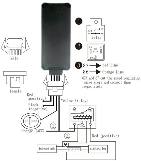
Connection method:
①Connecting the lock motor
②Connecting the relay
①Connecting the lock motor
②Connecting the relay
- The red positive pole is connected to the battery positive pole (+), and the black negative pole is connected to the battery negative pole (-).
- The power input line interface is connected to the positive and negative pole interface of the power supply (the positive and negative poles cannot be reversed)
- ACC line connected to ACC line on vehicle
- Yellow wire connected relay cuts off oil power or locks motor
Oil and electricity disconnection wiring method 1:
- Find out the “speed control handle control line”. The method: “speed control handle control line” is generally green or white, on the 4Pin connector of the controller.
- Measure the voltage of the speed control handle line with a multimeter. The voltage of the control line of the speed control handle is 0.8V by default (in the static positive state when ACC is on). When the speed control handle is adjusted to the highest speed, it is about 4.3v-5v.
- Change the speed control line into 2 lines.
- Connect the two lines of the cut speed control line to the two lines of the normally closed end of the relay.
Remarks: the oil and electricity cut-off function must be equipped with a relay specified by the manufacturer (it is recommended that electric vehicles use a 5V relay specified by the manufacturer, and automobiles use a 12V relay specified by the manufacturer)
Lock motor wiring method 2:
Adjust the multimeter to the DC voltage of 200V, connect the black pen to the negative pole of the battery, and the red pen to the controller line one by one. If the voltage is displayed as a line of 3~5v, it is judged to be a locked motor line, which can be connected with the yellow line.
Equipment Operation
5.1 Login location service platform
Please log in to the service platform designated by the dealer for corresponding settings and function operations.
Default login account: IMEI number (see sticker) default login password: 123456
5.2 Downloading Mobile Application
Please log in to the website designated by the dealer to download the mobile applicationsoftware for installation.
Default login account: IMEI number (see sticker) default login password: 123456
5.2 Downloading Mobile Application
Please log in to the website designated by the dealer to download the mobile applicationsoftware for installation.

5.3 SMS command operation
- Status query1
Format: Status# - Set SOS number
Format: SOS, a, number# - Address query
Format DW or 123
Switch ON/OFF

- card installation: install the SIM card in the correct directionwhen the external power is not connected. After fastening the SIM card, turn the switch to 0n, and then cover the surface.
- card retrieval: disconnect the external power and turn the switch to 0ff before removing the SIM card.
Remarks:
- The SIM card needs to be enabled with data traffic, SIM and voice functions.

- Close the upper cover
Installation Instructions
7.1 Installation instructions
The terminal shall be installed in a concealed manner.
It is recommended that a professional organization designated by the dealer install the terminal. Installation precautions:
The terminal shall be installed in a concealed manner.
It is recommended that a professional organization designated by the dealer install the terminal. Installation precautions:
- Concealed installation, pay attention to waterproof.
- Please turn on the device terminal battery switch before use.During installation, ensure that (indicator light) is upward and there is no metal shield above.
- It can be fixed with tie or sponge double-sided adhesive tape.
Working Description
- the external power equipment starts automatically, and the power indicator (red) is always on
- use the backup battery independently without external power, and the power indicator (red) flashes slowly
- search network signal (yellow indicator) and GPS signal (blue indicator )flash quickly
- after normal operation, the network signal (yellow indicator) and GPS signal (blue indicator) flash slowly
- SOS alarm:long press sos for 3 seconds, the device dials the SOS number, and the other party can realize the listening function after answering.
Battery use safety
Please use the battery specified by the original manufacturer of your terminal. Using any other accessories will invalidate all warranty services.
If the terminal is damaged due to the use of non original accessories, the manufacturer will not bear any warranty liability.
If the terminal is damaged due to the use of non original accessories, the manufacturer will not bear any warranty liability.
- Do not let metal objects cause short circuit of battery contactor
- Do not bend or forcibly open the battery
- Do not immerse the battery in water or put it on fire
- The battery must be charged near room temperature, if the temperature is low 0℃ or above 45℃, the battery may not work
- It is forbidden to use batteries with deformed appearance, discoloration, liquid leakage or damaged outer packaging
- It is forbidden to disassemble and transform the battery
Troubleshooting
If you feel abnormal when operating the terminal, please refer to the following problems and solutions. If you cannot solve the problem, please contact the seller or service provider.
| Como prpb,let | Problems arose | Tens of settlement |
| Poor signal reception | When terminals are used in areas with poca-recmtion, such as near high-rise buildings or basements, radio waves cannot be effectively transmitted | Use the terminal at a good signal position |
| Unable to connect to the network | SIM card not installed properly | Check SIM card |
| Dirt on metal surface of SIM card | Wipe with a clean cloth | |
| Out of GSM service area | Please move to the network service provider service area | |
| Weak signal | Please love to a place with strong signal and try,again | |
| Location infcmationnot found | SIM card is not enabled with GPRS function | Please contact the network service provider to activate GPI* function. |
| Always reply “failed to get location” | Please contact your dealer |
![]()
Documents / Resources
 |
thingsys G17H Vehicle Positioning Terminal [pdf] User Guide G17H Vehicle Positioning Terminal, G17H, Vehicle Positioning Terminal, Positioning Terminal, Terminal |