TDT iL24 Digital Logic Interface
Introduction
The iL24 Digital Logic Interface is designed to communicate with external behavioral components using 24 bits of 5 V or 3.3 V TTL logic signals. It features 12 input bits and 12 output bits, with each direction having 4 addressable bits and 1 addressable byte.
Specifications
| Feature | Description |
|---|---|
| Input Bits | 12 |
| Output Bits | 12 |
| Voltage Levels | 5 V or 3.3 V TTL |
| Maximum Current | 6 mA per bit |
Notices
- The information contained in this document is provided “as is,” and is subject to being changed, without notice. TDT shall not be liable for errors or damages in connection with the furnishing, use, or performance of this document or of any information contained herein.
- The latest versions of TDT documents are always online at https://www.tdt.com/docs/
iL24 Digital Logic Interface
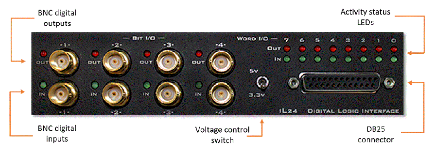
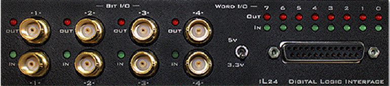
The iL24 module can communicate with external behavioral components using 24 bits of 5 V or 3.3 V TTL logic signals. There are 12 input bits and 12 output bits. Each direction has 4 addressable bits and 1 addressable byte.
- There are four bit-wise inputs and four bit-wise outputs available with BNC connectors and status light for each
- The DB25 connector has access to all 24 addressable bits
- Two rows of 8 status LEDs on the front panel show the state of the word input and output bits
- The front panel switch toggles between +3.3 V and +5 V logic for all 24 bits of I/O on the iL24
- Each bit can source up to 6 mA maximum current
For information on software control of the iL24, see the Synapse Manual.
iL24m Manifold
The iL24 comes with a manifold of BNC connectors for easier access to the Word Input and Word Output bits.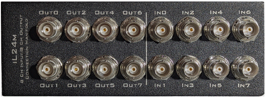
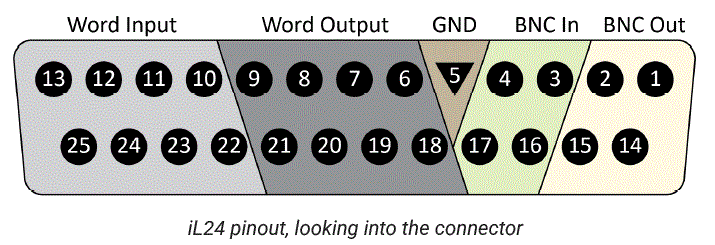
DB25 Pinout
Parts
| Pin | Name | Description | Pin | Name | Description |
| 1 | BO1 | BNC Output | 14 | BO2 | BNC Output |
| 2 | BO3 | 15 | BO4 | ||
| 3 | BI1 | BNC Input | 16 | BI2 | BNC Input |
| 4 | BI3 | 17 | BI4 | ||
| 5 | GND | Ground | 18 | DO0 | Word Output |
| 6 | DO1 | Word Output | 19 | DO2 | |
| 7 | DO3 | 20 | DO4 | ||
| 8 | DO5 | 21 | DO6 | ||
| 9 | DO7 | 22 | DI0 | Word Input | |
| 10 | DI1 | Word Input | 23 | DI2 | |
| 11 | DI3 | 24 | DI4 | ||
| 12 | DI5 | 25 | DI6 | ||
| 13 | DI7 |
© 2016-2025 Tucker-Davis Technologies, Inc. (TDT). All rights reserved.
- Tucker-Davis Technologies
- 11930 Research Circle
- Alachua, FL 32615 USA
- Phone: +1.386.462.9622
- Fax: +1.386.462.5365
FAQ
- What is the purpose of the iL24 Digital Logic Interface?
- `The iL24 is designed to communicate with external behavioral components using TTL logic signals.
- How many input and output bits does the iL24 support?
- The iL24 supports 12 input bits and 12 output bits.
- Where can I find the latest documentation?
- The latest documentation is available at TDT’s website.
- How can I control the iL24 via software?
- For software control, refer to the Synapse Manual.
Documents / Resources
 |
TDT iL24 Digital Logic Interface [pdf] Instruction Manual iL24 Digital Logic Interface, iL24, Digital Logic Interface, Logic Interface, Interface |