![]() UM2958 STEVAL-FCU001V2
UM2958 STEVAL-FCU001V2
Flight Controller Unit Evaluation Board
User Manual
Getting started with the STEVAL-FCU001V2 flight controller unit evaluation board for mini drones
Introduction
The STEVAL-FCU001V2 evaluation board is designed as a simple platform to develop flight controller unit (FCU) solutions for quadcopters.
A complete sample firmware project (STSW-FCU001) allows you to begin flying small or medium sized quadcopters equipped with DC motors (thanks to four 30 V-9 A on-board MOSFETs), and larger quadcopters with external ESCs (that is, STEVAL- ESC001V1 or STEVAL-ESC002V1).
You can control the board via BLE connectivity (using a smartphone or a tablet) or via an RF receiver module connected to the PWM input port.
The system embeds a high-performance Arm® Cortex®-M4 microcontroller unit (STM32F401CCU6), an iNEMO inertial module (LSM6DSR), a Bluetooth® low energy module (BlueNRG-M0A), power management circuitry that allows fast charge of the battery (STC4054), and four STL10N3LLH5 N-channel 30 V, 9 A, PowerFLAT(TM) STripFET(TM) V Power MOSFET to drive a quadcopter motor.
An additional barometric pressure sensor (LPS22HH) provides altitude estimation.
This reference design can be used to develop sophisticated auto-navigation algorithms thanks to more than 100 DMIPS available on the STM32 and the scalability of the board, which can be connected to the Teseo-LIV3F GNSS module or to a set of Time-of-Flight sensors like the VL53L5CX.
The system passed the RF test for European certification, FCC certification, and IC certification (FCC ID: S9NBNRGM0AL and IC: 8976C-BNRGM0AL).
Notice: For dedicated assistance, please submit a request through our online support portal at www.st.com/support.
Getting started
1.1 Board overview
The STEVAL-FCU001V2 evaluation board features:
- Compact flight controller unit (FCU) evaluation board complete with sample firmware for a small or medium-sized quadcopter
- On-board LiPo one-cell battery charger
- Possibility to drive directly four DC brushed motors through the low voltage on-board MOSFET or alternatively use external ESC for DC brushless motor configuration
1.2 Package contents
The STEVAL-FCU001V2 evaluation board package contains:
- the evaluation board itself
- the ST-LINK adapter with its programming cable to be used with the ST-LINK/V2 or STLINK-V3SET

1.3 System requirements
To use the board, the following system specifications are required:
- a Windows PC (7, 8, 8.1, 10, 11) with a preinstalled STM32 software development tool (STM32CubeIDE)
- ST-LINK/V2 (or STLINK/V3SET) in-circuit debugger/programmer, its USB driver (STSW-LINK009) and, optionally, the STM32CubeProgrammer for firmware download
- a LiPo one-cell battery to be connected to the battery connector (BT1) for stand-alone operation or a USB type A to Micro-USB male cable to connect the STEVAL-FCU001V2 evaluation board to the PC for power supply
- four DC motors suitable for 3.7 V operation directly connected to the board, or four DC brushless motors with four matching electronic speed controllers (such as STEVAL-ESC001V1 or STEVAL-ESC002V1 evaluation boards)
- four propellers suitable for the motors chosen
- ST_BLE_DRONE app for Android and iOS to be used with the STSW-FCU001 demonstration firmware
Note: Choose the propellers, motors, and the electronic speed controller (ESC) on the basis of the quadcopter size and weight.
Hardware description
The STEVAL-FCU001V2 main components are:
- STL10N3LLH5 30 V, 9 A, STripFETTM V Technology in a PowerFLATTM 3×3.3 package
- STM32F401CCU6 high performance Arm® Cortex®-M4 MCU with 256 Kbytes of Flash memory, 64 kBytes of RAM in a UFQFPN48 package
- LPS22HH high-performance MEMS nano pressure sensor: 260-1260 hPa absolute digital output barometer
- LSM6DSR iNEMO inertial module: 3D accelerometer and 3D gyroscope
- BlueNRG-M0A very low-power network processor module for Bluetooth® low energy 2
- LD39015 low quiescent voltage regulator
- STC4054 800 mA Li-ion and LiPo battery charger directly from USB
- USBULC6-2M6 ultra large bandwidth ESD protection

2.1 Hardware architecture overview
The whole system can be split in five different subsystems:
- microcontroller
- sensors
- connectivity
- battery management
- DC motor drivers
The sensors and the BlueNRG-M0A devices are connected to the microcontroller through two separate SPI peripherals. 2.2 Board connectors
The STEVAL-FCU001V2 evaluation board includes several hardware connectors (see Figure 5):
- USB micro B female plug
- Battery two-pin header connector
- Four motor two-pin header connectors
- UART four-pin header connector
- I²C four-pin header connector
- PWM input six-pin header connector
- Micro SWD connector (1.27 mm pitch)
As shown in Figure 3, some of these connectors have not the pins soldered on the board to leave the maximum freedom to users.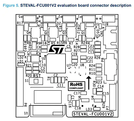 The board can be powered via a USB connector or one-cell battery. By connecting both, the embedded battery charger uses the USB current to charge the battery.
Considering the specific application, it is highly recommended to use a LiPo battery with a high value of maximum discharge current rating (this parameter is often indicated with “number of C” where “C” is battery capacity). Thus, a 500 mAh battery with a discharge rating of 50 C has a maximum sustained load of 25 amps: compare this value to the sum of the current absorbed by the motors (x4) and the on-board electronics, which is negligible with respect to the motors.
Table 1. Battery 2-pin header connector (BT1)
| Pin | Signal | Description |
| + | VBAT+ | one-cell LiPo battery (3.4 to 4.2 V) |
| – | GND | – |
Note: The + is placed on the board left side (refer to Figure 3 for board orientation). It is important to ensure correct polarity connection as reverse battery protection is not implemented.
The four motor connectors can be used to connect a one-cell 3.7 V motor to each of them or to external ESCs.
Depending on the kind of motor, you have to solder the male strip line on the board or directly on the motors pins.
In the STSW-FCU001, an association between Px connector and motor placement on the drone structure has been considered (for further information, refer to UM2512 on www.st.com).
Table 2. Motor 2-pin header connectors (P1, P2, P4, P5)
| Pin | Signal | Description |
| 1 | VBAT+ | To be connected to motor (+) for DC motors(1) |
| 2 | MOTOR- | To be connected to motor (-) for DC motors(2) |
- Not connected for external ESC.
- To be connected to PWM inputs for external ESC.
Note: The + is placed on the board right side (refer to Figure 3 for board orientation).
Note: You can refer to the datasheet of the motor to distinguish + and – wire colors.
As in many commercial flight controllers, the STEVAL-FCU001V2 hosts a UART and an I²C to connect external peripherals.
Table 3. UART 4-pin header connector (P7)
| Pin | Signal | Description |
| 1 | VDD | 3.3 V of STM32 |
| 2 | GND | |
| 3 | USART1_RX | RXD for STM32 |
| 4 | USART1_TX | TXD for STM32 |
Note: Pin 1 is placed on the board top side (refer to Figure 3 for board orientation).
Table 4. I2C 4-pin header connector (P3)
| Pin | Signal | Description |
| 1 | VDD | 3.3 V of STM32 |
| 2 | I2C2_SDA | – |
| 3 | I2C2_SCL | – |
| 4 | GND | – |
Note: Pin 1 is placed on the board top side (refer to Figure 3 for board orientation).
The STSW-FCU001 evaluation software has been designed to offer the possibility of controlling the drone through a smartphone app (ST_BLE_DRONE) and by an external remote controller.
In this case, you have to connect a remote controller RX module to the P6 connector of the STEVAL-FCU001V2 evaluation board.
The firmware implementation is compatible with a pulse period modulation (PPM) receiver:
- CH1 is related to AIL control with roll function
- CH2 is related to ELE control with pitch function
- CH3 is related to THR control with thrust function
- CH4 is related to RUD control with yaw function
Table 5. PWM inputs six-pin header connector (P6)
| Pin | Signal | Description |
| 1 | VBAT+ | Directly connected to battery (+) |
| 2 | TIM2_CH1 | TIM2_CH1 for RF RX PWM IN signal CH1 |
| 3 | TIM2_CH2 | TIM2_CH2 for RF RX PWM IN signal CH2 |
| 4 | TIM2_CH3 | TIM2_CH3 for RF RX PWM IN signal CH3 |
| 5 | TIM2_CH4 | TIM2_CH4 for RF RX PWM IN signal CH4 |
| 6 | GND | – |
Note: Pin 1 is placed on the board top side (refer to Figure 3 for board orientation).
Table 6. Debugging micro-SWD connector (P8)
| Pin | Signal | Description |
| 1 | VDD |
| Pin | Signal | Description |
| 2 | SWDD | SWD debugging data line |
| 3 | GND | |
| 4 | SWCLK | SWD debugging clock line |
| 5 | GND | – |
| 6 | N.C. | – |
| 7 | GND | – |
| 8 | N.C. | – |
| 9 | GND | – |
| 10 | NRST | NReset for STM32 |
For further details on debugging, refer to Section 2.3.
Note: Pin 1 is placed on the board bottom-right side (refer to Figure 3 for board orientation).
2.3 ST-LINK connection
To update the firmware, use the ST-LINK/V2 or ST-LINK/V3SET debugger programmer by plugging the adapter and the cable (provided in the STEVAL-FCU001V2 package as described in Section 1.2) to the board and then to the laptop.
Note: ST-LINK/V2 and STLINK/V3SET are not included in the package. Go to www.st.com to order them.
System setup guide
The board is provided with a preinstalled firmware STSW-FCU001. The firmware is also retrievable on www.st.com as open source code and the ST BLE Drone app to exploit its functionalities.
3.1 How to use the board with the preinstalled firmware
Step 1. Connect a LiPo one-cell battery to BT1 battery connector of the STEVAL-FCU001V2, paying attention to the polarity, as shown below. Caution: There is no protection for reverse connection on the circuit.
Step 2. Activate the Bluetooth® connection on your smartphone and enable ST_BLE_DRONE app to use it.
Step 3. Open ST_BLE_DRONE app on your smartphone and tap [Start discovering].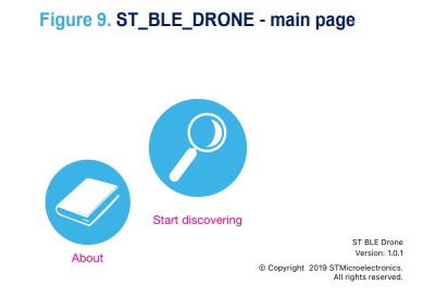 Step 4. Select the DRN2100 device from the list to connect the smartphone to the board.
LD2 turns on to signal that the connection is active. Your remote control appears on the screen.
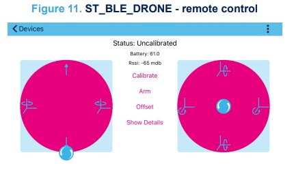
The app shows the battery value and RSSI of the Bluetooth low energy connectivity.
Note: To avoid issues, in case you are using more than one STEVAL-FCU001V2 evaluation boards in your operating space, you have to reprogram them to show a different name to avoid issues.
Step 5. Tap [Show Details] to make the MEMS motion sensor data appear on the screen.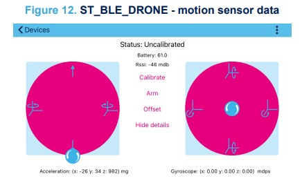
By moving the evaluation board, you can see how data change.
The STSW-FCU001 firmware also implements the calibration and arming procedure. The ST_BLE_DRONE app permits running these functions remotely.
Step 6. Put the evaluation board on a plane and tap [Calibrate] to remove any sensor offset.
The app shows the “Calibrated” status and LED LD1 will switch on.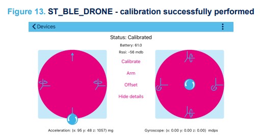 Step 7. To allow flight, tap the button related to the arming procedure.
The status message change to “Armed” and LD2 turns on.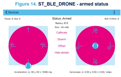 Step 8. Move the smartphone left lever up and down.
The voltage on M1, M2, M3 and M4 change according to the drone flight rules.
3.2 How to use the board with your own firmware
Step 1. Connect a LiPo one-cell battery to BT1 battery connector of the STEVAL-FCU001V2, paying attention to the polarity, as shown below. Caution: There is no protection for reverse connection on the circuit.
Step 2.Connect the ST-LINK adapter included in the package to the ST-LINK/V2 (or STLINK/V3SET) and the STEVAL-FCU001V2 evaluation board.
Step 3.Connect a USB cable to a PC and to the micro-USB connector (CN1) to supply the board.
Step 4.Check that the LD3 is switched ON.
Step 5. Optionally, download the STSW-FCU001 firmware package.
Step 6. Program the board (refer to UM2329).
Note: It is recommended to connect the USB cable during the programming phase to avoid issues on the power supply.
Once the firmware fine tuning session finishes, you can remove the connection to the micro-USB cable and the ST-LINK adapter.
Schematic diagrams


Bill of materials
Table 7. Bill of materials
| Item | Q.ty | Ref. | Part/Value | Description | Manufacturer | Order code |
| 1 | 1 | BT1 | Battery Connector, siptm2002 | Strip line male 1X2 pitch 2.54 mm 90 degrees | Adam Tech | PH1RA-02-UA |
| 2 | 1 | CN1 | Micro_USB 2.0 Female SMt, microusb7025481 | Micro-USB connector | Molex | 47590-0001 |
| 3 | 6 | C1,C7,C14, C17,C19,C2 1 | 1uF, smc0402, 16V, +/-10% | Ceramic capacitor XR7 | Any | Any |
| 4 | 12 | C2,C3,C4,C 5,C6,C10,C1 2,C15,C18,C 20,C22,C23 |
100nF, smc0402, 16V, +/-10% | Ceramic capacitor XR7 | Any | Any |
| 6 | 2 | C8,C9 | 15pF, smc0402, 16V, +/-10% | Ceramic capacitor XR7 | Any | Any |
| 7 | 2 | C11,C16 | 4.7uF, smc0402, 16V, +/-10% | Ceramic capacitor XR7 | Any | Any |
| 8 | 1 | C13 | 4.7nF, SMC0402, 16V, +/-10% | Ceramic capacitor XR7 | Any | Any |
| 9 | 4 | D1,D2,D3,D 4 | BAT60J, sod323, 10V, 3A | 10 V general purpose signal Schottky diode | ST | BAT60J |
| 10 | 1 | D5 | ESDA7P60-1U1M, SMD1610 | High-power transient voltage suppressor (TVS) | ST | ESDA7P60-1U1M |
| 11 | 3 | LD1,LD2,LD 3 | RED LED, smd0603, SMD | Red LED | OSRAM Opto | LRQ396 |
| 13 | 1 | P1 | Motor_Panel1, siptm2002 | Strip line male 1X2 pitch 2.54 mm 90 degrees | Adam Tech | PH1RA-02-UA |
| 14 | 1 | P2 | Motor_Panel3, siptm2002 | Strip line male 1X2 pitch 2.54 mm 90 degrees | Adam Tech | PH1RA-02-UA |
| 15 | 1 | P3 | i2Q, siptm4004 | Strip line male 1X4 pitch 2.54 mm | Wurth Elektronik | 61300411121 |
| 16 | 1 | P4 | Motor_Panel2, siptm2002 | Strip line male 1X2 pitch 2.54 mm 90 degrees | Adam Tech | PH1RA-02-UA |
| 17 | 1 | P5 | Motor_Panel4, siptm2002 | Strip line male 1X2 pitch 2.54 mm 90 degrees | Adam Tech | PH1RA-02-UA |
| 18 | 1 | P6 | FC_Signal, siptm6006 | Strip line male 1X6 pitch 2.54 mm | Wurth Elektronik | 61300611121 |
| Item | Q.ty | Ref. | Part/Value | Description | Manufacturer | Order code |
| 19 | 1 | P7 | USART, siptm4004 | Strip Line male 1X4 pitch 2.54 mm | Wurth Elektronik | 61300411121 |
| 20 | 1 | P8 | SWD, Ampmode10X1M27 | Connector 2X5 pitch 1,27 mm | SAMTEC | FTSH-105-01-F-D-K |
| 21 | 4 | Q1,Q2,Q3,Q 4 | STL6N3LLH6, powerFLAT2X2 |
N-channel 30 V, 0.021 Ohm typ., 6 A STripFET H6 power MOSFET in a PowerFLAT 2×2 package |
ST | STL6N3LLH6 |
| 22 | 1 | R1 | 47k, smr0402, 1/16W, +/-1% | SMD thick film resistor | Any | Any |
| 23 | 4 | R2, R3, R6, R8 | 1K, smr0402, 1/16W, +/-1% | SMD thick film resistors | Any | Any |
| 24 | 7 | R4, R5, R7, R9, R10, R23, R24 | 10K, smr0402, 1/16W, +/-1% | SMD thick film resistors | Any | Any |
| 25 | 1 | R11 | 20K, smr0402, 1/16W, +/-1% | SMD thick film resistor | Any | Any |
| 26 | 4 | R12, R13,R16, R17, R25 | smr0603, 1/16W, +/-1% | SMD thick film resistors | Any | Any |
| 27 | 4 | R14, R15, R18, R19 | NA, smr0402, 1/16W, ±1% | SMD Thick Film Resistor | Any | Any |
| 28 | 2 | R20, R21 | 2.2K, smr0402, 1/16W, ±1% | SMD Thick Film Resistor | Any | Any |
| 29 | 3 | R22,R27,R2 8 | 100K, smr0402, 1/16W, ±1% | SMD Thick Film Resistor | Any | Any |
| 30 | 1 | R26 | 1M, SMR0402, 1/16W, ±1% | SMD Thick Film Resistor | Any | Any |
| 31 | 1 | R29 | 510R, smr0402, 1/16W, ±1% | SMD Thick Film Resistor | Any | Any |
| 32 | 1 | R30 | 5.1K, smr0402, 1/16W, ±1% | SMD Thick Film Resistor | Any | Any |
| 33 | 1 | S1 | Reset, PushKMR22 | Push Botton | C&K | KMR231GLFS |
| 34 | 1 | U1 | BLUENRG-M0A, spbtrfle | Very low power network processor module for Bluetooth® low energy v4.2 | ST | BlueNRG-M0 |
| 35 | 1 | U2 | STM32F401CCU, UFQFPN48X7X7 | High- performance access line, Arm Cortex- M4 core with DSP and FPU, 256 Kbytes of Flash memory, 84 MHz CPU, | ST | STM32F401CCU |
| Item | Q.ty | Ref. | Part/Value | Description | Manufacturer | Order code |
| ART accelerator | ||||||
| 36 | 1 | U3 | USBULC6-2M6(uQFN), uQFN6X145X1 | Ultra large bandwidth ESD protection | ST | USBULC6-2M6 |
| 37 | 1 | U4 | STC4054GR, SOT23L5 | 800 mA standalone linear Li-Ion battery charger with thermal regulation | ST | STC4054GR |
| 39 | 1 | U6 | LD39015M33R, sot23l5 | 150 mA low quiescent current low noise voltage regulator | ST | LD39015M33R |
| 40 | 1 | U7 | LPS22HHTR, HLGA10X2X2X07 | H igh- performance MEMS nano pressure sensor: 260-1260 hPa absolute digital output barometer |
ST | LPS22HHTR |
| 41 | 1 | U8 | LSM6DSRTR, lga14X2m5X3X086 | iNEMO inertial module: 3D accelerometer and 3D gyroscope | ST | LSM6DSRTR |
| 42 | 1 | Y1 | 16 MHz, 15 ppm | Quartz | NDK | NX2520SA-16,000000MHz- STD-CSW-4 |
| 43 | 1 | None | ARM-JTAG-20-10 | Mini-board and cable | Olimex LTD | ARM-JTAG-20-10 |
Board versions
| Finished good | Schematic diagrams | Bill of materials |
| STEVAL$FCU001V2A(1) | STEVAL$FCU001V2A schematic diagrams | STEVAL$FCU001V2A bill of materials |
1. This code identifies the STEVAL-FCU001V2 evaluation board first version.
Regulatory compliance information
Formal Notices Required by the U.S. Federal Communications Commission (FCC)
Responsible party’s contact located in the United States: name: Francesco Doddo; address: STMicroelectronics Inc, 200 Summit Drive, Suite 405, Burlington MA, 01803, U.S.A.; e-mail: francesco.doddo@st.com This device complies with part 15 of the FCC Rules. Operation is subject to the following two conditions: (1) This device may not cause harmful interference, and (2) this device must accept any interference received, including interference that may cause undesired operation. Changes or modifications not expressly approved by the manufacturer could void the user’s authority to operate the equipment.
Note: This equipment has been tested and found to comply with the limits for a Class B digital device, pursuant to part 15 of the FCC Rules. These limits are designed to provide reasonable protection against harmful interference in a residential installation. This equipment generates, uses and can radiate radio frequency energy and, if not installed and used in accordance with the instructions, may cause harmful interference to radio communications.
However, there is no guarantee that interference will not occur in a particular installation. If this equipment does cause harmful interference to radio or television reception, which can be determined by turning the equipment off and on, the user is encouraged to try to correct the interference by one or more of the following measures:
- Reorient or relocate the receiving antenna.
- Increase the separation between the equipment and receiver.
- Connect the equipment into an outlet on a circuit different from that to which the receiver is connected.
- Consult the dealer or an experienced radio/TV technician for help.
Standard applied: FCC CFR Part 15 Subpart B. Test method applied: ANSI C63.4 (2014).
Formal Product Notice Required by Industry Canada
Responsible party’s contact located in Canada: name: John Langner; address: STMicroelectronics, Inc., 350 Burnhamthorpe Road West, Suite 303 L5B 3J1, Mississauga, ON, Canada; e-mail: john.langner@st.com
Innovation, Science and Economic Development Canada Compliance
This device contains licence-exempt transmitter(s)/receiver(s) that comply with Innovation, Science and Economic Development Canada’s licence exempt RSS(s). Operation is subject to the following two conditions: (1) This device may not cause interference. (2) This device must accept any interference, including interference that may cause undesired operation of the device.
Standard applied: ICES-003 Issue 7 (2020), Class B. Test method applied: ANSI C63.4 (2014).
Notice for the European Union
The kit STEVAL-FCU001V2 is in conformity with the essential requirements of the Directive 2014/53/EU (RED)
and of the Directive 2015/863/EU (RoHS). Harmonized standards applied are listed in the EU Declaration of Conformity.
Notice for the United Kingdom
The kit STEVAL-FCU001V2 is in compliance with the UK Radio Equipment Regulations 2017 (UK SI 2017 No.
1206 and amendments) and with the Restriction of the Use of Certain Hazardous Substances in Electrical and Electronic Equipment Regulations 2012 (UK SI 2012 No. 3032 and amendments). Applied standards are listed in the UK Declaration of Conformity.
Revision history
Table 9. Document revision history
| Date | Revision | Changes |
| 22-Aug-2023 | 1 | Initial release. |
| 24-Jun-2024 | 2 | Updated Introduction, Section 2: Hardware description, Section 3: System setup guide, Section 3.1: How to use the board with the preinstalled firmware, Section 3.2: How to use the board with your own firmware and Section 4: Schematic diagrams. |
IMPORTANT NOTICE – READ CAREFULLY
STMicroelectronics NV and its subsidiaries (“ST”) reserve the right to make changes, corrections, enhancements, modifications, and improvements to ST products and/or to this document at any time without notice. Purchasers should obtain the latest relevant information on ST products before placing orders. ST products are sold pursuant to ST’s terms and conditions of sale in place at the time of order acknowledgment.
Purchasers are solely responsible for the choice, selection, and use of ST products and ST assumes no liability for application assistance or the design of purchasers’ products.
No license, express or implied, to any intellectual property right is granted by ST herein.
Resale of ST products with provisions different from the information set forth herein shall void any warranty granted by ST for such product.
ST and the ST logo are trademarks of ST. For additional information about ST trademarks, refer to www.st.com/trademarks. All other product or service names are the property of their respective owners.
Information in this document supersedes and replaces information previously supplied in any prior versions of this document.
© 2024 STMicroelectronics – All rights reserved![]()
Documents / Resources
 |
STMicroelectronics UM2958 STEVAL-FCU001V2 Flight Controller Unit Evaluation Board [pdf] User Manual UM2958, UM2958 STEVAL-FCU001V2 Flight Controller Unit Evaluation Board, STEVAL-FCU001V2 Flight Controller Unit Evaluation Board, Flight Controller Unit Evaluation Board, Controller Unit Evaluation Board, Evaluation Board |