![]()
Built-in actuator and meter
User Manual www.myvirtuosohome.com
www.myvirtuosohome.com
Introduction
SmartDHOME thanks you for choosing this built-in actuator and meter for plant automation.
This module is a Z-Wave-certified device, compatible with any Z-Wave-enabled network. All mains-powered Z-Wave devices also perform the signal repetition function for battery-powered devices, helping to eliminate possible signal shadow areas.
This actuator allows you to control (activate/deactivate) the power line to which it has been connected and to send an immediate report of the energy consumption to the Z-Wave gateway to which it has been associated.
Description and features
This device has been designed for internal use.
LEGEND
| N | Neutral power supply |
| L | Power phase |
| IN | Input for power supply load |
| Ou T | Output for load (directly connected to IN) |
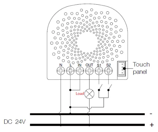
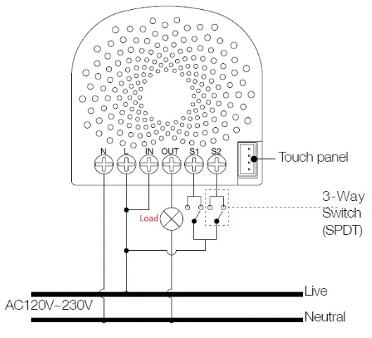
| s1 | External switch/button control |
| s2 | External switch/button control |
FEATURES
| Protocol | Z-Wave |
| Transmission frequency |
868.42 MHz |
| Signal range | 30 meters in open field |
| Operating voltage |
230 Vac |
| Stand-by power |
< 0.8 W |
| Measurement t accuracy |
+/- 3 W |
| Dimension | 42,5 (A) * 40 (L) * 20 (P) mm |
PACKAGE CONTENT
1 Built-in actuator and meter.
1 User manual.
Installation:
a. Inclusion
- Set the MyVirtuoso Home gateway in inclusion mode and press the button on the back of the device.
If the LED on the back of the device flashes green and then remains steady, the actuator has been included correctly. If the LED initially lights up red and then changes in color, then the inclusion has not occurred. Repeat the operation. - In case of successful inclusion, the LED will remain on. The color it will take depends on the output: it will be green with an output of 0 A – 5 A, yellow with an output of 5 A – 9 A, and red with an output of 9 A – 10.5 A.
b. Exclusion
Set the MyVirtuoso Home gateway in bypass mode, and press the button on the back of the device. If the exclusion is successful, the LED will change color again. In case of non-exclusion, however, the LED will remain in the color indicated in point 3: repeat the exclusion procedure.
Note: to avoid short circuits that could damage the device and to ensure safety during the installation phase,it is advisable to disconnect the general electric current.
Operation
As soon as the actuator is connected to the phase to be measured, it will be able to detect and transmit consumption data or activate the home automation rules defined by the
MyVirtuoso Home gateway.
The line can also be disconnected manually by simply pressing the switch on the device.
Connection diagrams
a. Input current 120 VAC – 230 Vac

b. Input current 120 VAC – 230 VAC with 24 Vdc output
 c. Input Current 24 Vdc
d. Input current 24 VDC with 120 VAC – 230 Vac output

e. Deviated scheme for external button
Warranty and Customer care
Visit the link for warranty information:
https://www.ecodhome.com/en/shop-online/termsconditions.html
If you encounter technical problems or malfunctions, visit the website:
http://helpdesk.smartdhome.com/users/register.aspx
After a short registration, you can open a ticket online, also attaching images. One of our technicians will answer you as soon as possible. ![]()
SmartDHOME Srl
www.smartdhome.com
info@smartdhome.com
Rev. 02/2021 P/N 01335-1302-00
Documents / Resources
 |
SmartDHOME 1302 Built-in Actuator and Meter [pdf] User Manual 1302, Built-in Actuator and Meter |


